
Ballistic Performance of Polyurea-Reinforced Ceramic/Metal Armor Subjected to Projectile Impact


Abstract
:1. Introduction
2. Experimental Materials and Target Configuration
2.1. Material Characteristics of the Testing Target
2.2. Fabrication Process of Testing Target
2.3. Target Configuration
3. Experimental Setup and Testing Method
4. Experimental Results
5. Failure Mechanisms
5.1. Perforation of Targets
5.2. Damage Pattern of the Targets
6. Conclusions
- (1)
- The polyurea layer shown could improve the ballistic performance of ceramic composite armor. The mass efficiency of polyurea-coated ceramic armor was found to be higher than that of ceramic/metal armor. The position of the polyurea layer also has a significant influence on ballistic performance. The targets in configuration F showed better ballistic performance. Compared with ceramic/metal armor, the mass efficiency of composite armor with a polyurea layer on the front face was improved from 6.69 to 12.68 on average at the same speed range (700–825 m/s), and increased by 89%.
- (2)
- The damage characteristics of the different configuration targets are presented. It was found that the damage characteristics of the polyurea layer are related to its position in the layers, which influenced the failure mode of the targets.
- (3)
- Five failure patterns are presented from the experimental conditions: the shearing-hole, self-healing, spallation, perforation, and cracking.
- (4)
- SEM analysis of the polyurea layer was conducted. The results of the microscopic analysis show that the polyurea in configuration F demonstrated the micro-morphology of glass transition, which explains the high ballistic performance of targets in configuration F.
Author Contributions
Funding
Conflicts of Interest
References
- Prikhodko, S.V.; Ivasishin, O.M.; Markovsky, P.E.; Savvakin, D.G.; Stasiuk, O.O. Titanium Armor with Gradient Structure: Advanced Technology for Fabrication. In Advanced Technologies for Security Applications; Springer: Berlin/Heidelberg, Germany, 2020; pp. 127–140. [Google Scholar]
- Crouch, I.G. Body armour—New materials, new systems. Def. Technol. 2019, 15, 241–253. [Google Scholar] [CrossRef]
- Boldin, M.S.; Berendeev, N.N.; Melekhin, N.V.; Popov, A.A.; Nokhrin, A.V.; Chuvildeev, V.N. Review of ballistic performance of alumina: Comparison of alumina with silicon carbide and boron carbide. Ceram. Int. 2021, 47, 25201–25213. [Google Scholar] [CrossRef]
- David, N.V.; Gao, X.L.; Zheng, J.Q. Ballistic Resistant Body Armor: Contemporary and Prospective Materials and Related Protection Mechanisms. Appl. Mech. Rev. 2009, 62, 50802. [Google Scholar] [CrossRef]
- Serjouei, A.; Chi, R.; Zhang, Z.; Sridhar, I. Experimental validation of BLV model on bi-layer ceramic-metal armor. Int. J. Impact Eng. 2015, 77, 30–41. [Google Scholar] [CrossRef]
- Tang, R.T.; Wen, H.M. Predicting the perforation of ceramic-faced light armors subjected to projectile impact. Int. J. Impact Eng. 2017, 102, 55–61. [Google Scholar] [CrossRef]
- Dresch, A.B.; Venturini, J.; Arcaro, S.; Montedo, O.R.; Bergmann, C.P. Ballistic ceramics and analysis of their mechanical properties for armour applications: A review. Ceram. Int. 2021, 47, 8743–8761. [Google Scholar] [CrossRef]
- Dresch, A.B.; Venturini, J.; Bergmann, C.P. Improving the flexural-strength-to-density ratio in alumina ceramics with the addition of silicon nitride. Ceram. Int. 2021, 47, 3964–3971. [Google Scholar] [CrossRef]
- Savio, S.G.; Rao, A.S.; Reddy, P.R.S.; Madhu, V. Microstructure and ballistic performance of hot pressed & reaction bonded boron carbides against an armour piercing projectile. Adv. Appl. Ceram. 2019, 118, 264–273. [Google Scholar] [CrossRef]
- Vargas-Gonzalez, L.; Speyer, R.F.; Campbell, J. Flexural Strength, Fracture Toughness, and Hardness of Silicon Carbide and Boron Carbide Armor Ceramics. Int. J. Appl. Ceram. Technol. 2010, 7, 643–651. [Google Scholar] [CrossRef]
- Sun, M.; Cao, W.; Hu, D.; Zhang, N.; Chi, R. Effect of Cover Plate on the Ballistic Performance of Ceramic Armor. Materials 2020, 14, 1. [Google Scholar] [CrossRef]
- Luo, D.; Wang, Y.; Wang, F.; Cheng, H.; Zhu, Y. Ballistic Behavior of Oblique Ceramic Composite Structure against Long-Rod Tungsten Projectiles. Materials 2019, 12, 2946. [Google Scholar] [CrossRef] [PubMed] [Green Version]
- Goh, W.L.; Zheng, Y.; Yuan, J.; Ng, K.W. Effects of hardness of steel on ceramic armour module against long rod impact. Int. J. Impact Eng. 2017, 109, 419–426. [Google Scholar] [CrossRef]
- Tan, M.; Zhang, X.; Goh, W.L.; Luo, B.; Bao, K. Study on transition from dwell/interface defeat to penetration of long-rod projectile impacting silicon carbide. Int. J. Fract. 2019, 219, 65–87. [Google Scholar] [CrossRef]
- Gour, G.; Idapalapati, S.; Goh, W.L.; Shi, X.-P. Equivalent protection factor of bi-layer ceramic metal structures. Def. Technol. 2022, 18, 384–400. [Google Scholar] [CrossRef]
- Serjouei, A.; Gour, G.; Zhang, X.; Idapalapati, S.; Tan, G.E.B. On improving ballistic limit of bi-layer ceramic-metal armor. Int. J. Impact Eng. 2017, 105, 54–67. [Google Scholar] [CrossRef]
- Zhang, R.; Han, B.; Lu, T.J. Confinement effects on compressive and ballistic performance of ceramics: A review. Int. Mater. Rev. 2021, 66, 287–312. [Google Scholar] [CrossRef]
- Ryan, S.; Gallardy, D.; Zellner, M.; Bunn, J.; Nguyen, L.; Swoboda, P. Investigating the relationship between radial pre-stress magnitude and ballistic projectile dwell in heavy confined ceramic targets. Int. J. Impact Eng. 2021, 157, 104002. [Google Scholar] [CrossRef]
- Luo, B.-Y.; Goh, W.-L.; Chen, Z.; Yuan, J.-M. Laterally pre-compressed SiC tiles against long rod impact. Def. Technol. 2018, 14, 585–589. [Google Scholar] [CrossRef]
- Ben-Dor, G.; Dubinsky, A.; Elperin, T. Optimization of two-component composite armor against ballistic impact. Compos. Struct. 2005, 69, 89–94. [Google Scholar] [CrossRef]
- Zhang, B.; Wang, Y.; Du, S.; Yang, Z.; Cheng, H.; Fan, Q. An analysis of bi-layer ceramic armor and optimization of protection efficiency. Mater. Des. 2021, 203, 109633. [Google Scholar] [CrossRef]
- Zhao, Z.-N.; Han, B.; Zhang, R.; Zhang, Q.; Zhang, Q.-C.; Ni, C.-Y.; Lu, T.J. Enhancement of UHMWPE encapsulation on the ballistic performance of bi-layer mosaic armors. Compos. Part B Eng. 2021, 221, 109023. [Google Scholar] [CrossRef]
- Peng, L.; Tan, M.T.; Zhang, X.; Han, G.; Xiong, W.; Al Teneiji, M.; Guan, Z.W. Investigations of the ballistic response of hybrid composite laminated structures. Compos. Struct. 2022, 282, 115019. [Google Scholar] [CrossRef]
- Chen, Z.; Xu, Y.; Li, M.; Li, B.; Song, W.; Xiao, L.; Cheng, Y.; Jia, S. Investigation on Residual Strength and Failure Mechanism of the Ceramic/UHMWPE Armors after Ballistic Tests. Materials 2022, 15, 901. [Google Scholar] [CrossRef] [PubMed]
- Sun, Y.-X.; Wang, X.; Ji, C.; Zhao, C.-X.; Liu, P.-L.; Meng, L.; Zhang, K.; Jiang, T. Experimental investigation on anti-penetration performance of polyurea-coated ASTM1045 steel plate subjected to projectile impact. Def. Technol. 2021, 17, 1496–1513. [Google Scholar] [CrossRef]
- Fallon, C.; McShane, G.J. Impact mitigating capabilities of a spray-on elastomer coating applied to concrete. Int. J. Impact Eng. 2019, 128, 72–85. [Google Scholar] [CrossRef]
- Jiang, Y.; Zhang, B.; Wei, J.; Wang, W. Study on the impact resistance of polyurea-steel composite plates to low velocity impact. Int. J. Impact Eng. 2019, 133, 103357. [Google Scholar] [CrossRef]
- Yang, F.; Li, Z.; Liu, Z.; Zhuang, Z. Shock Loading Mitigation Performance and Mechanism of the PE/Wood/PU/Foam Structures. Int. J. Impact Eng. 2021, 155, 103904. [Google Scholar] [CrossRef]
- Zhang, P.; Wang, Z.; Zhao, P.; Zhang, L.; Jin, X.C.; Xu, Y. Experimental investigation on ballistic resistance of polyurea coated steel plates subjected to fragment impact. Thin-Walled Struct. 2019, 144, 106342. [Google Scholar] [CrossRef]
- Clifton, R.J.; Wang, X.; Jiao, T. A physically-based, quasilinear viscoelasticity model for the dynamic response of polyurea. J. Mech. Phys. Solids 2016, 93, 8–15. [Google Scholar] [CrossRef] [Green Version]
- Grujicic, M.; He, T.; Pandurangan, B.; Svingala, F.R.; Settles, G.S.; Hargather, M.J. Experimental Characterization and Material-Model Development for Microphase-Segregated Polyurea: An Overview. J. Mater. Eng. Perform. 2011, 21, 2–16. [Google Scholar] [CrossRef]
- Guo, H.; Chen, Y.; Tao, J.; Jia, B.; Li, D.; Zhai, Y. A viscoelastic constitutive relation for the rate-dependent mechanical behavior of rubber-like elastomers based on thermodynamic theory. Mater. Des. 2019, 178, 107876. [Google Scholar] [CrossRef]
- Mott, P.H.; Giller, C.B.; Fragiadakis, D.; Rosenberg, D.A.; Roland, C.M. Deformation of polyurea: Where does the energy go? Polymer 2016, 105, 227–233. [Google Scholar] [CrossRef]
- Grujicic, M.; Pandurangan, B.; d’Entremont, B. The role of adhesive in the ballistic/structural performance of ceramic/polymer–matrix composite hybrid armor. Mater. Des. 2012, 41, 380–393. [Google Scholar] [CrossRef]
- Mohotti, D.; Ngo, T.; Raman, S.N.; Ali, M.; Mendis, P. Plastic deformation of polyurea coated composite aluminium plates subjected to low velocity impact. Mater. Des. 2014, 56, 696–713. [Google Scholar] [CrossRef]
- Stergiou, T.; Baxevanakis, K.P.; Roy, A.; Sazhenkov, N.A.; Nikhamkin, M.S.; Silberschmidt, V.V. Impact of polyurea-coated metallic targets: Computational framework. Compos. Struct. 2021, 267, 113893. [Google Scholar] [CrossRef]
- Bogoslovov, R.B.; Roland, C.M.; Gamache, R.M. Impact-induced glass transition in elastomeric coatings. Appl. Phys. Lett. 2007, 90, 221910. [Google Scholar] [CrossRef] [Green Version]


| Material | Material Properties | |||||
|---|---|---|---|---|---|---|
| Polyurea | Density (kg/m3) | Solid content | Tensile strength (MPa) | Tearing strength (MPa) | Elongation | Solidification time (s) |
| 1010 | ≥96% | 10 | ≥40 KN/m | 400% | 45 | |
| SiC ceramic | Density (kg/m3) | Vickers hardness (MPa) | Bending strength (MPa) | Compressive strength (MPa) | Crystal density (μm) | Elasticity modulus (GPa) |
| 3130 | 2600 | 400 | 2200 | 5 | 430 | |
| Armor steel | Density (kg/m3) | Brinell hardness (HB) | Yeld strength (MPa) | Tensile strength (MPa) | Elongation | |
| 7850 | 500 | 1400 | 1700 | 10% | ||
| Aluminum 6061-T6 | Density (kg/m3) | Tensile strength (MPa) | Yield strength (MPa) | Elongation (%) | ||
| 2850 | 318 | 257 | 9.9 | |||
| Tungsten alloy | Density (kg/m3) | Yield strength (MPa) | Elongation (%) | Rockwell hardness (HRC) | ||
| 17600 | 742 | 8.8 | 27 | |||
| Material | Chemical Composition | ||||||||
|---|---|---|---|---|---|---|---|---|---|
| Armor steel | C | Si | Mn | P | S | Cr | Ni | Mo | B |
| 0.32 | 0.4 | 1.2 | 0.01 | 0.003 | 1.0 | 1.8 | 0.7 | 0.005 | |
| Aluminium 6061-T6 | SI | Fe | Cu | Mn | Mg | Cr | Zn | Ti | Al |
| 0.59 | 0.369 | 0.246 | 0.063 | 1.025 | 0.201 | 0.103 | 0.028 | 97.37 | |
| Tungsten alloy | W | Ni | Fe | ||||||
| 93 | 5.1 | 1.9 | |||||||
| Configuration of Targets | ||||
|---|---|---|---|---|
| Group | F | M | B | C |
| Configuration (mm) | (5p)/4.5c/4.5s | 4.5c/(5p)/4.5s | 4.5c/4.5s/(5p) | 10c/4.5s |
| Areal density (g/cm2) | 5.464 | 6.685 | ||
| Configuration Template | Moment 1 | Moment 2 | Moment 3 | Moment 4 | Moment 5 |
|---|---|---|---|---|---|
| F | 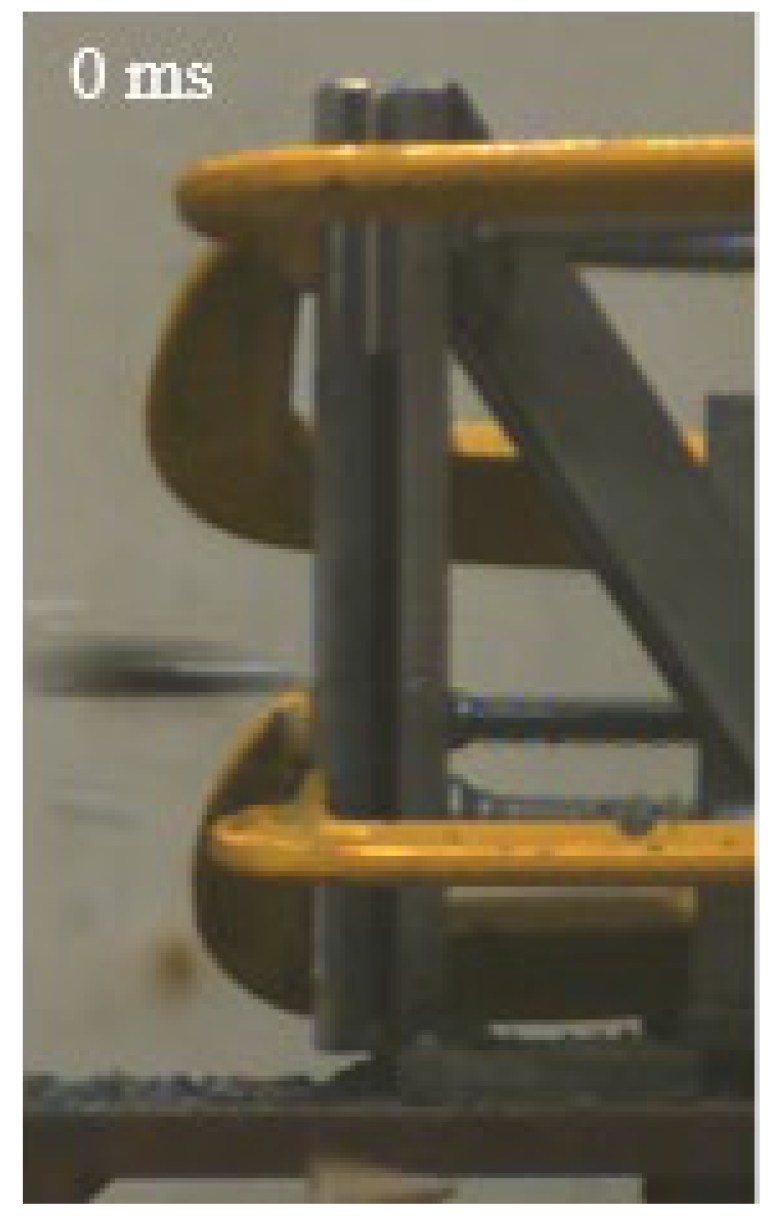 | 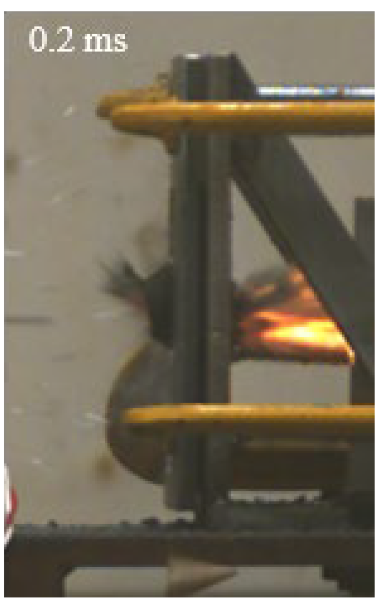 | 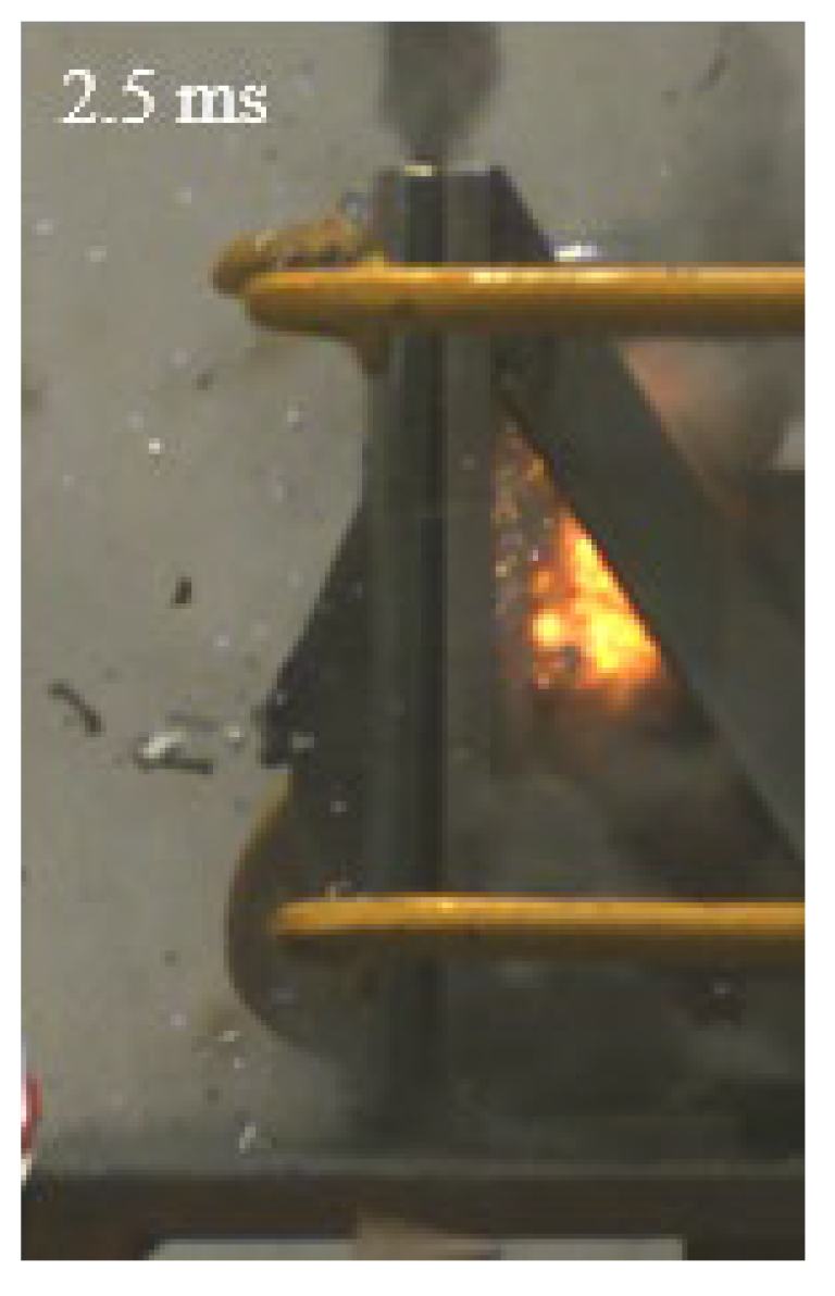 | 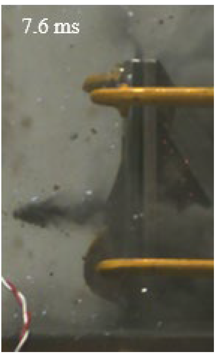 | 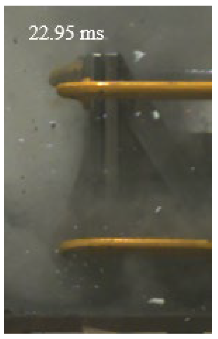 |
| M |  | 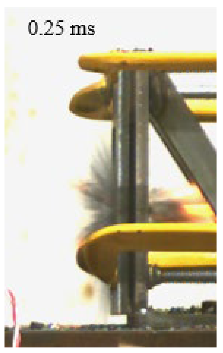 | 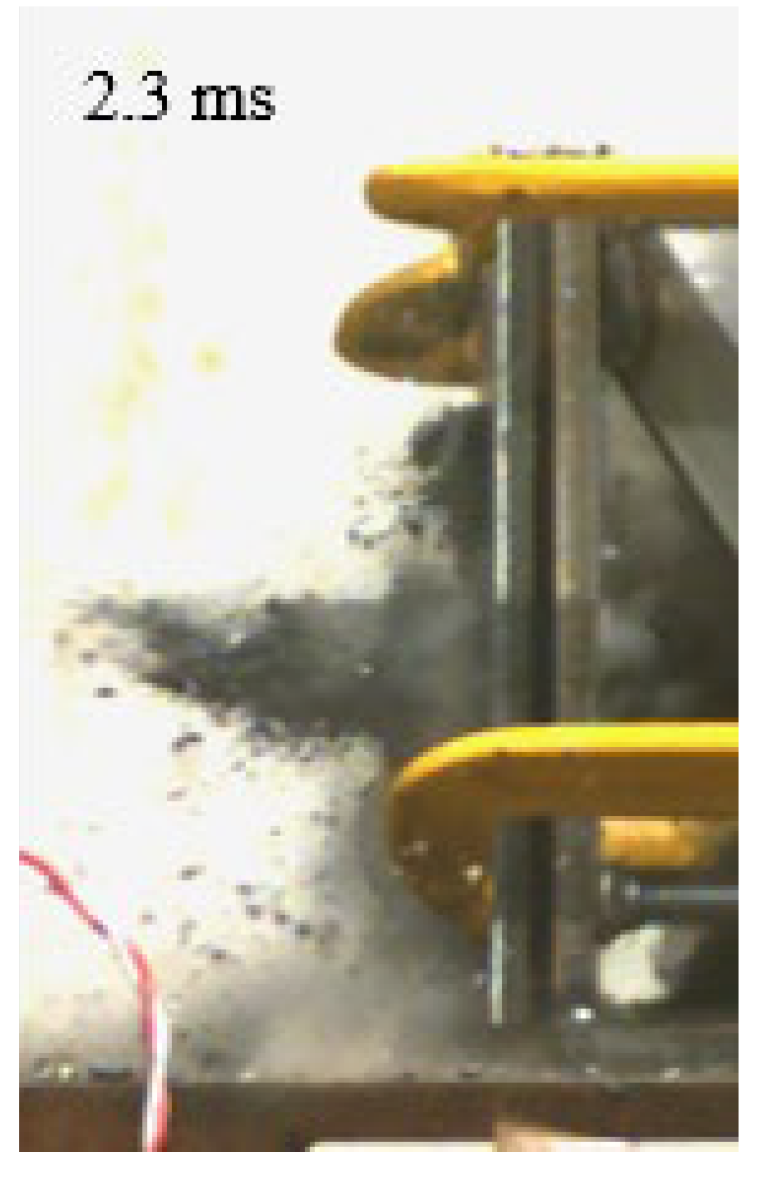 | 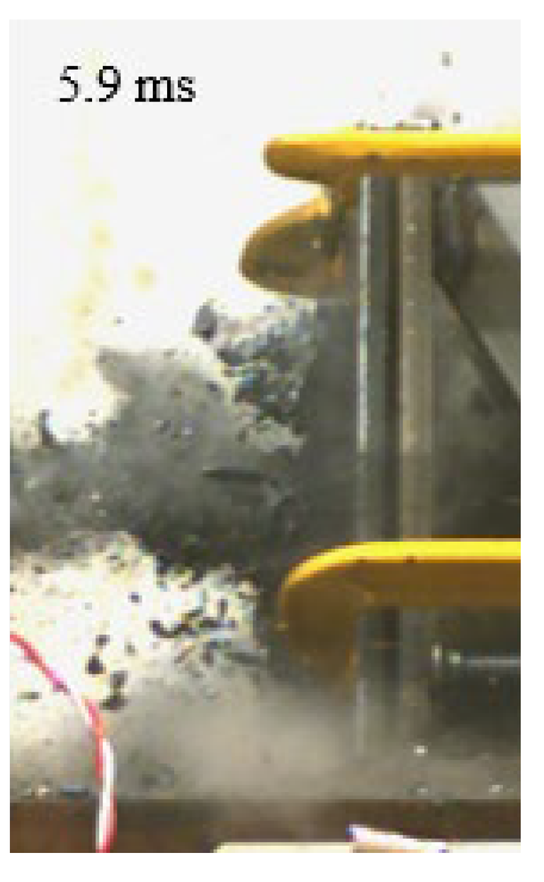 | 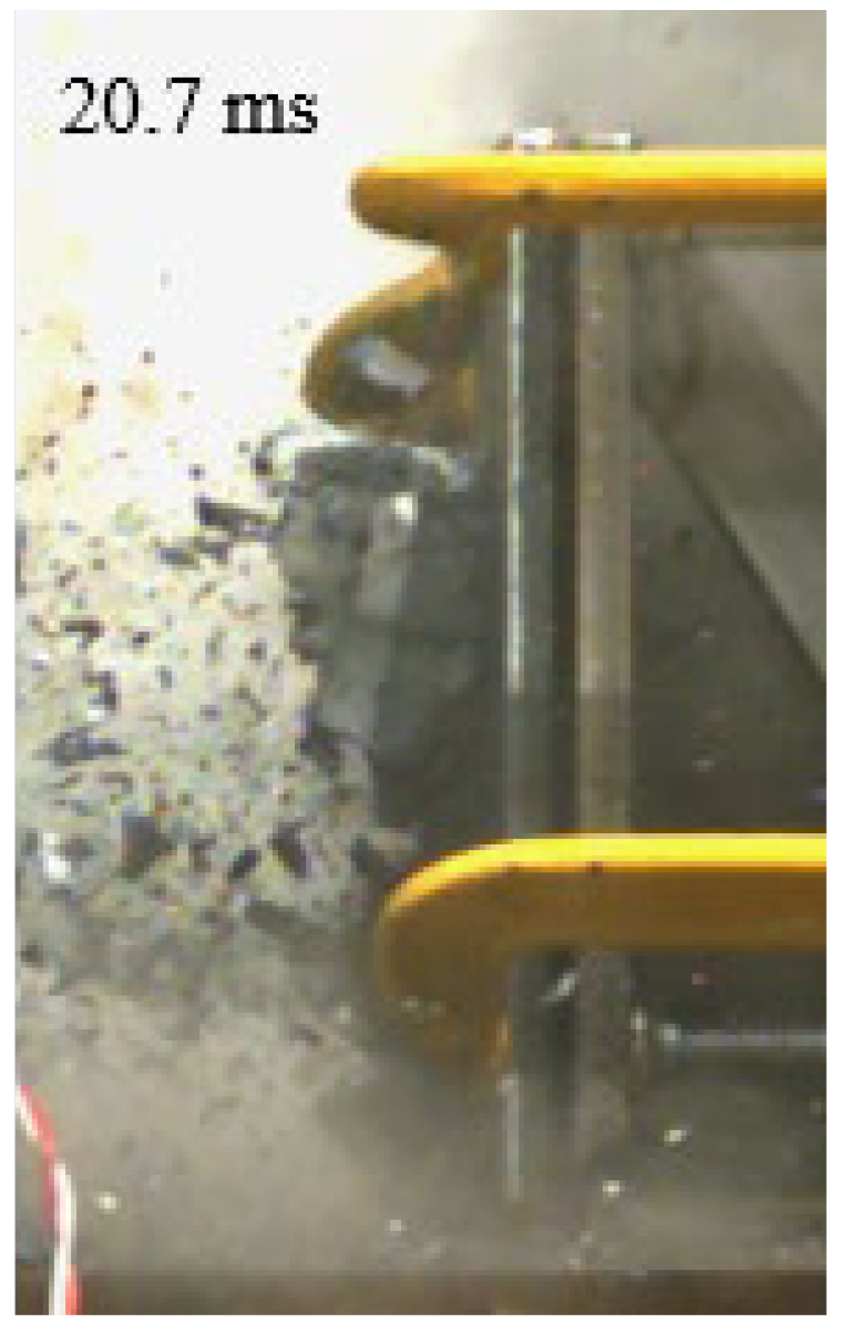 |
| B | 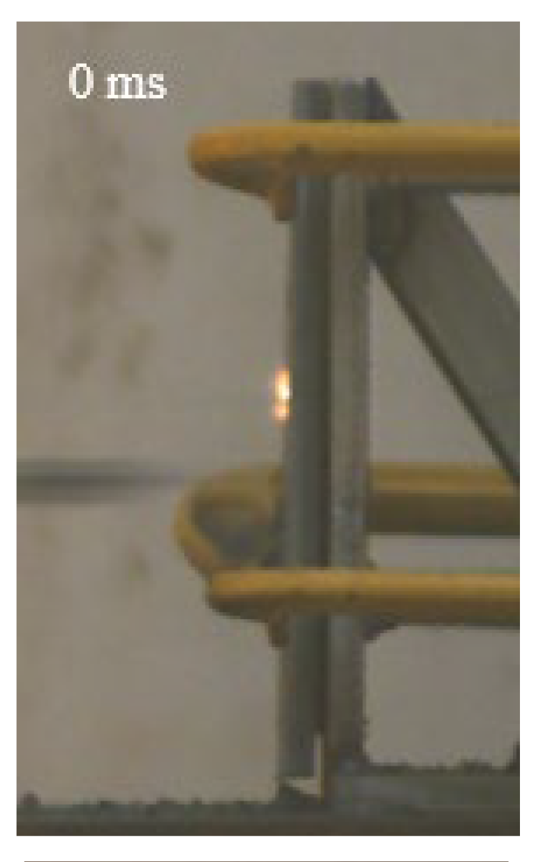 | 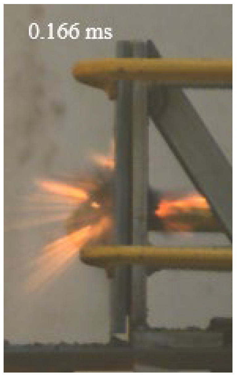 | 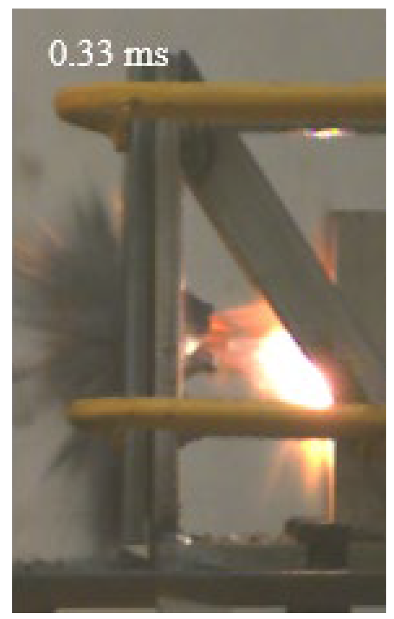 |  |  |
| C |  |  |  |  |  |
| Configuration of the Targets | F | M | B | C |
|---|---|---|---|---|
| Front face |  |  | 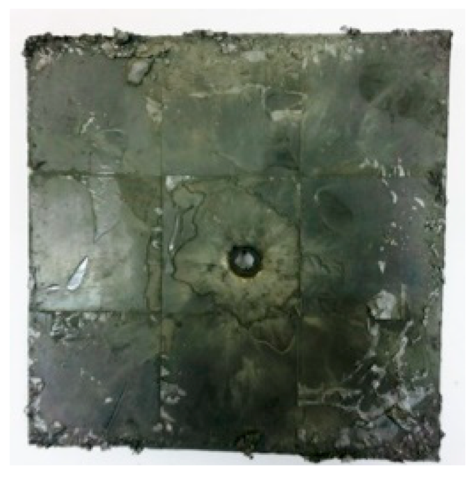 |  |
| Rear face | 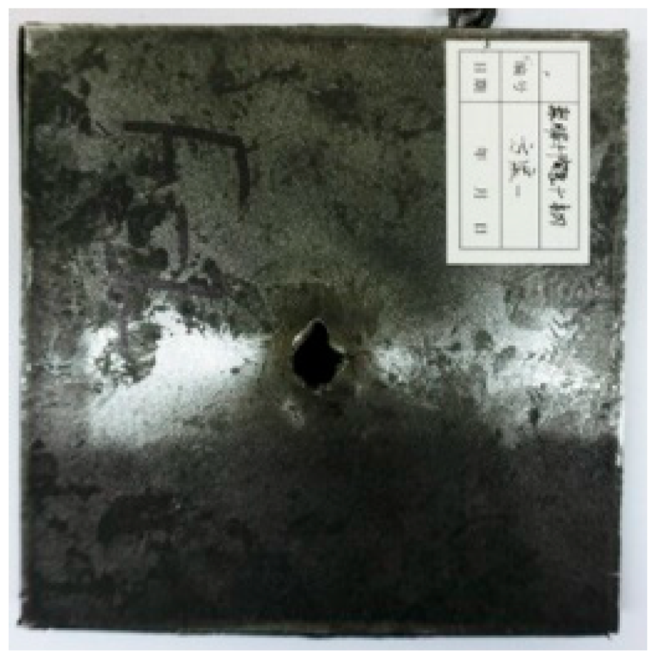 | 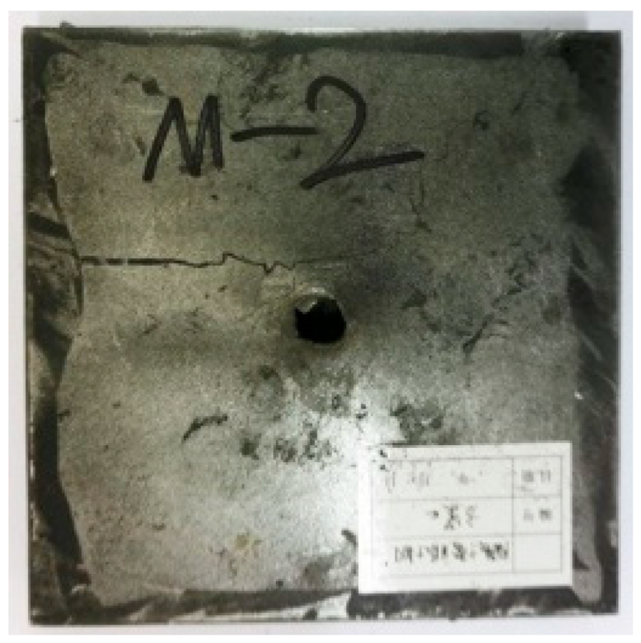 |  | 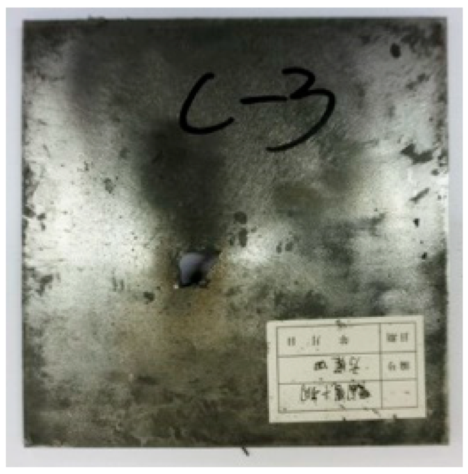 |
| Configuration Template | F3 | M3 | B1 | B5 | B2 |
|---|---|---|---|---|---|
| Damage Patterns | a. Shearing-Hole | b. Self-Healing | c. Spallation | d. Perforation | e. Cracking |
| Front face | 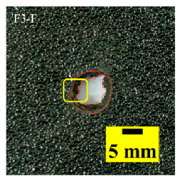 | 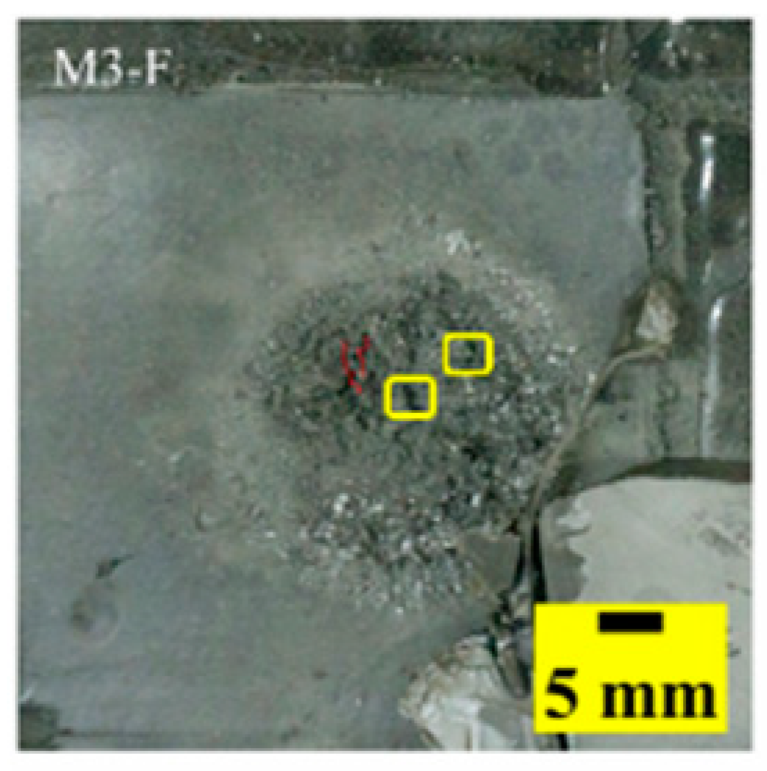 | 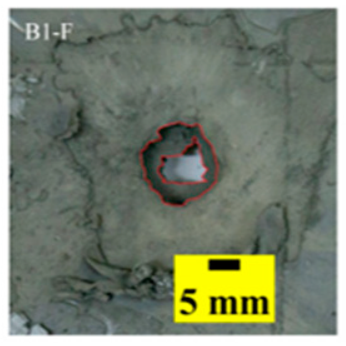 |  | 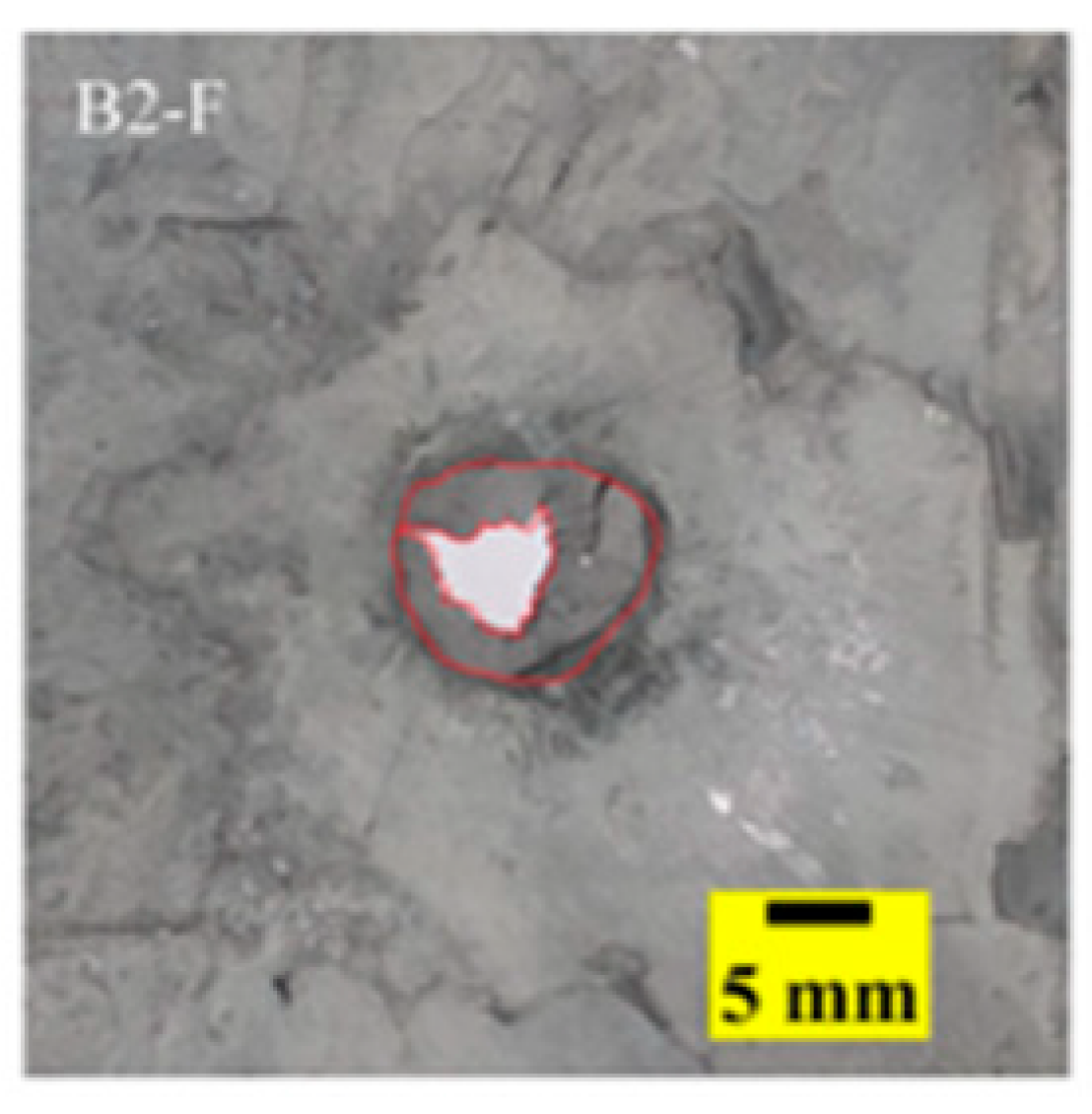 |
| Rear face | 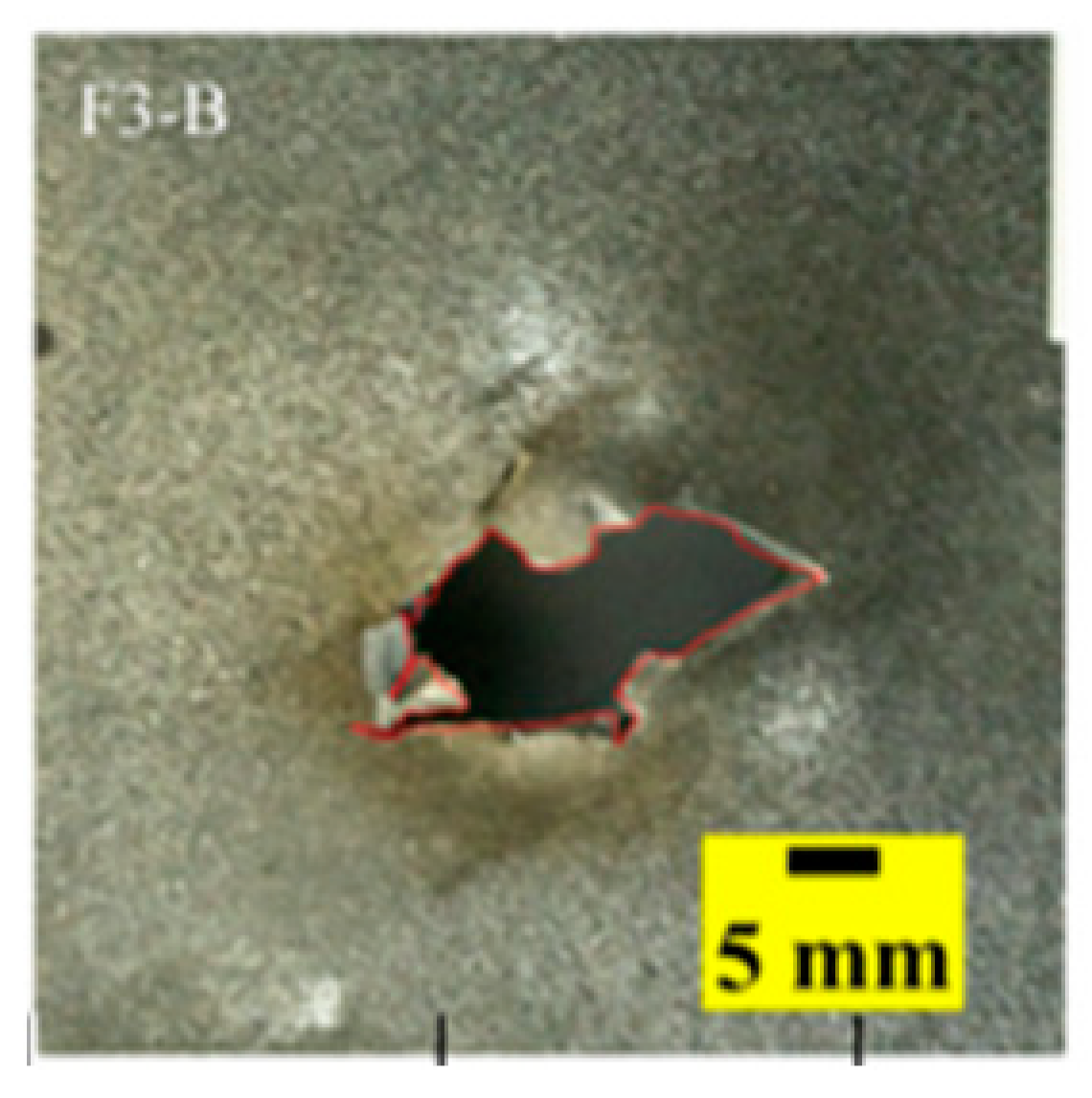 | 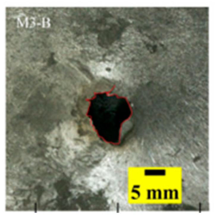 |  | 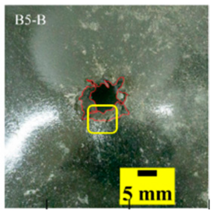 | 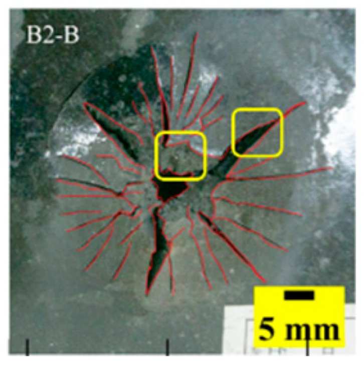 |
Publisher’s Note: MDPI stays neutral with regard to jurisdictional claims in published maps and institutional affiliations. |
© 2022 by the authors. Licensee MDPI, Basel, Switzerland. This article is an open access article distributed under the terms and conditions of the Creative Commons Attribution (CC BY) license (https://creativecommons.org/licenses/by/4.0/).
Share and Cite
Si, P.; Liu, Y.; Yan, J.; Bai, F.; Huang, F. Ballistic Performance of Polyurea-Reinforced Ceramic/Metal Armor Subjected to Projectile Impact. Materials 2022, 15, 3918. https://doi.org/10.3390/ma15113918
Si P, Liu Y, Yan J, Bai F, Huang F. Ballistic Performance of Polyurea-Reinforced Ceramic/Metal Armor Subjected to Projectile Impact. Materials. 2022; 15(11):3918. https://doi.org/10.3390/ma15113918
Chicago/Turabian StyleSi, Peng, Yan Liu, Junbo Yan, Fan Bai, and Fenglei Huang. 2022. "Ballistic Performance of Polyurea-Reinforced Ceramic/Metal Armor Subjected to Projectile Impact" Materials 15, no. 11: 3918. https://doi.org/10.3390/ma15113918
APA StyleSi, P., Liu, Y., Yan, J., Bai, F., & Huang, F. (2022). Ballistic Performance of Polyurea-Reinforced Ceramic/Metal Armor Subjected to Projectile Impact. Materials, 15(11), 3918. https://doi.org/10.3390/ma15113918