Article

Experimental and Numerical Investigation of Static and Dynamic Characteristics of Bio-Oils and SAE40 in Fluid Film Journal Bearing

by
Muhammad Imran Sadiq
*,
Wan Aizon W. Ghopa
,
Mohd Zaki Nuawi
,
Mohammad Rasidi Rasani
and
Mohd Anas Mohd Sabri
Department of Mechanical and Manufacturing Engineering, University Kebangsaan Malaysia, Bangi 43600, Selangor, Malaysia
*
Author to whom correspondence should be addressed.
Materials 2022, 15(10), 3595; https://doi.org/10.3390/ma15103595
Submission received: 28 March 2022 / Revised: 20 April 2022 / Accepted: 21 April 2022 / Published: 18 May 2022
(This article belongs to the Special Issue Advances in Computational Materials Tribology)

Abstract

:
Mineral-based oils are the market leaders when it comes to their consumption in different types of rotating machines. Recently, a lot of attention has been given to the bio-oils and lubricants due to their better thermophysical, tribological, and environmental characteristics for use in journal bearing and other rotating machines. The superior physical properties of bio-oils have instigated this research in order to evaluate their dynamic characteristics that can cause the harmful dynamic instabilities in rotating machinery. The dynamic characteristics of the fluid film are influenced by temperature, eccentricity ratio, and rotational speed. In this work, the effect of temperature is experimentally measured on the dynamic viscosity of bio-oils and mineral-based oil. The dynamic viscosity measured is then computationally used to estimate the hydrodynamic pressure response of three bio-oils (rapeseed, palm olein, and soybean) and SAE40, a mineral-based oil, to check their performance in the rotor bearing system. It is found that at 40 °C, the hydrodynamic pressure for SAE40 is observed to be 2.53, 2.72, and 3.32 times greater than those of rapeseed, palm olein, and soybean oil, respectively, whereas, at 125 °C, the hydrodynamic pressure for SAE40 is observed to be 8% and 4.3% less than those of rapeseed and palm olein, respectively, but 14% greater than that of soybean oil. Hence, the increasing temperature has less effect on the viscosity and hydrodynamic pressure of bio-oils compared to SAE40. Therefore, for high-temperature applications, the bio-oils can be used with further processing. The superior response of bio-oils is also an indication for better dynamic characteristics.

1. Introduction

The governing equation of hydrodynamic lubrication, the Reynolds equation, was established in 1886. From the results of Tower and Petroff, Reynolds derived the basic equation of the hydrodynamic theory of lubrication of a journal bearing from the Navier–Stokes equations using many assumptions. The Reynolds equation is a partial differential equation and cannot be solved in its full form without making certain assumptions to simplify the equation and obtain the solution. There are two general simplifications: the infinitely long bearing (L/d = ∞) and the short bearing assumption (∂p/∂z >> ∂p/∂x). In addition, the solution obtained by making the short bearing assumption is much simpler than that from the infinite long bearing assumption [1].
Since then, many works on the solutions of the equation have been published. In journal bearings, the film thickness is not a linear function of the variables such as load, rotational speed, viscosity, stiffness, and damping. For the case of infinitely long bearings, the generalized Reynolds equation, which is a partial differential equation, can be reduced to an ordinary differential equation. The solution of the problem can be immediately derived by integration. However, for journal bearings of finite length, researchers could not succeed in obtaining the general solution for the finite bearing problem. It has even been stated that the exact solution of the Reynolds equation is only possible if the viscosity is constant and the film thickness is a linear function of the variables [2]. The numerical analysis of a plain journal bearing with nanoparticles and lubricating oil added, which uses a modified Reynolds equation considering the time-dependent inertia effects at rotating speeds with turbulence effects, is also investigated. The results show that adding the nanoparticles to an optimized level increases the critical speed, load carrying capacity, and also the overall stiffness and damping of the system [3]. This has become the norm in modern day research to derive and manipulate the Reynolds equation as per the desired operating and boundary conditions. The function of temperature distribution in the bearing oil film is obtained by coupling the Reynolds equation of hydrodynamic lubrication for short bearings of symmetric geometry with the energy equation [4].
It is important to evaluate the performance of journal bearings mathematically by considering different bio-lubricants. This is because the oil whirl and oil whip instabilities are associated mainly with the performance of the journal bearing. For this purpose, the equations are derived for performance evaluation of the journal bearing in terms of load-carrying capacity, oil film thickness, frictional force, and torque. Previously, the evaluation was carried out using the traditional mineral-based lubricants. The development of a mathematical model for the performance evaluation of a journal bearing using bio-lubricants would provide new horizons in terms of bio-lubricants research [5]. In the numerical analysis of journal bearing dynamic characteristics based on CFD, the results show that the film stiffness coefficient increases with the rotational speed, and the speed has little effect on the damping coefficient [6]. It is also important to model the flow in both laminar and turbulent regions to see how the different flow regimes affect the hydrodynamic pressure. It is also reported that revolution speed of the journal has a strong effect on the hydrodynamic film pressure [7].
The most popular mesh-based methods in CFD are the finite difference method (FDM), finite element method (FEM), and finite volume method (FVM) [8]. The most widespread mesh-based approach relies on FVM [9]. The popularity of the FVM in CFD stems from the high flexibility it offers as a discretization method. It owes much of its flexibility and popularity to the fact that discretization is carried out directly in the physical space with no need for any transformation between the physical and the computational coordinate system. The FVM is suitable for complex geometries. The grid defines only the control volume boundaries and need not be related to a coordinate system. Another advantage of the finite-volume method is that mass, momentum, and energy are automatically conserved, as the integral forms of the governing equations are solved. ANSYS Fluent employs the FVM method for the analysis. Many researchers have used the ANSYS Fluent software to carry out the oil film analysis [10,11,12,13,14,15,16]. The temperature variation for different objects and environments can also be measured using CFD [17]. The variation in pressure is also observed when the refinement in grid size is carried out. By changing the grid size, the improvement in accuracy of the results is observed. The average value of pressure is 12% greater than the results obtained by using a coarse grid [18].
The bio-lubricants are environment friendly, renewable, and biodegradable. This gives them an edge over the conventional mineral-based lubricants, which are toxic to the environment and are also non-biodegradable [19,20]. Furthermore, bio-lubricants have good tribological and physical properties, which gives them an edge over the mineral-based lubricants [21]. Therefore, it is important to make use of bio-oils that can contribute to a better environment and enhanced machine life.
The journal bearings can be evaluated by the static and dynamic characteristics under different thermal operating conditions [22]. The static characteristics are evaluated by estimating the oil film pressure, load-carrying capacity, and related forces acting on the oil film, whereas the dynamic characteristics are evaluated by stiffness (Kxx, Kxy, Kyy, Kyx) and damping coefficients (Cxx, Cxy, Cyy, Cyx). The cavitation and journal whirl are used to evaluate the static characteristics, dynamic characteristics, and stability of journal bearings [23]. The majority of the testing carried out to evaluate the performance of bio-oils is performed through the use of a high-frequency reciprocating test rig [20]. Therefore, it is important to develop a test rig to experimentally test these oils to obtain more accurate and precise results. Bio-oils are reported to have good stiffness characteristics when tested against the synthetic and mineral-based oils [24]. Similarly, in gas-lubricated micro-bearings, the temperature increase has an inverse effect on the viscosity of gas, which ultimately weakens the load-carrying capacity and stability of micro-bearings [22].
Thus, in this paper, the performance of bio-oils (rapeseed, palm olein, and soybean) and SAE40 is computationally evaluated in terms of hydrodynamic pressure, in order to determine how the bio-oils behave under different dynamic conditions in fluid film journal bearings. This is novel area of research that has not yet been experimentally and numerically simulated for bio-oils and lubricants. The short bearing assumption is used for analysis purposes. Furthermore, using different eccentricity ratios, the dynamic characteristics are also evaluated.

2. Theoretical Background

2.1. Static Performance Evaluation

The nonlinear fluid film forces generated by the journal bearing may be derived by considering the solution to the Reynolds equation. The Reynolds equation for laminar, iso-viscous, and iso-thermal flow may be written as [5]:
x ( h 3 η   p x ) + z ( h 3 η   p z ) = 6   U   h x + 12   h t
where h is the film thickness, p is the pressure developed in the film, and η is the oil film viscosity. Similarly, another important parameter to define a bearing that combines speed and load effects is often termed as the bearing characteristic number or the Sommerfeld number S:
S =   N   D   L W   [ R C ] 2
where η is the viscosity of the lubricant, N is the speed of shaft rotation, D is the diameter of the bearing, L is the bearing length, W is the applied load, R is the shaft radius, and C is the radial clearance.
In addition, the eccentricity ratio ε, is given by:
ε = e C
where e is the eccentricity and C is the radial clearance. The eccentricity ratio has a great impact on the hydrodynamic pressure, load carrying capacity, stiffness, and damping coefficients. The effect of eccentricity is also discussed in detail on the abovementioned parameters.

2.2. Dynamic Performance Evaluation

Assuming small changes in displacement and velocity and steady-state equilibrium position, the dynamics of the oil film is described by linearized stiffness and damping coefficients. The total forces in the x and y direction become [25]:
{ F x F y } = [ K x x K x y K y x K y y ] { x y } [ C x x C x y C y x C y y ] { x ˙ y ˙ }
F x = ( K x x x + K x y y + C x x x ˙ + C x y y ˙ )
F y = ( K y x x + K y y y + C y x x ˙ + C y y y ˙ )
where Kij and Cij are the stiffness and damping coefficients, respectively. The negative sign in the equation shows that the force is acting on the journal. The eight stiffness and damping coefficients depend on the steady-state condition of the journal and, in particular, the rotational speed.
From the above equations, we have two direct or principal stiffness coefficients:
K x x = F x / x
K y y = F y / y
where each stiffness coefficient relates the change in force in one direction due to the change in displacement in the same direction.
Similarly, two direct or principal damping coefficients are also present:
C x x = F x / x ˙
C y y = F y / y ˙
where the damping coefficients relate the small change in force due to a small change in velocity. In addition, the cross-coupled damping terms are equal:
C x y = C y x
The cross-coupled stiffness coefficients can be defined as:
K x y = F x / y
K y x = F y / x
The coefficient Kyx relates to a vertical force due to a displacement in the x direction. Thus, the horizontal and vertical directions are coupled. Almost all structures have cross-coupled stiffness terms, but most are symmetric in nature, meaning Kxy = Kyx. The cross-coupled stiffnesses are detrimental because, instead of damping the whirling motion of the rotor such as the direct damping, these cross-coupled stiffnesses combine to produce a force in the whirl direction, increasing the shaft vibration. When the direct damping is unable to dissipate the energy induced by the cross-coupled stiffness force, the natural frequency (generally, the first natural frequency with forward whirling direction) will become unstable, causing the journal to whirl at this frequency [25].
In this work, the dimensionless stiffness and damping coefficients are determined for various eccentricity ratios. These coefficients are important in defining the overall dynamic characteristics of the fluid film bearing under different loading conditions.

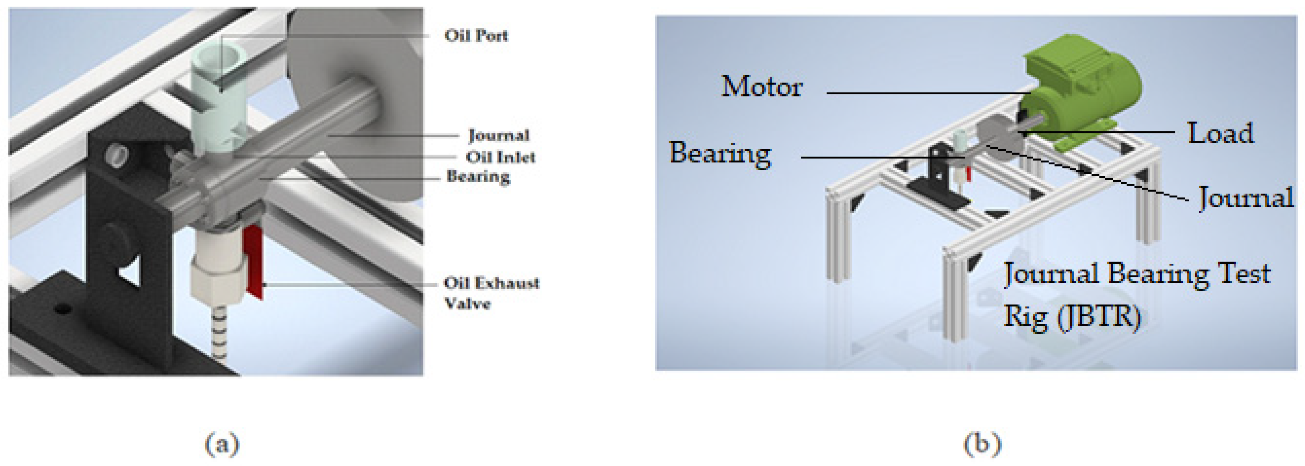
3. Materials and Methods

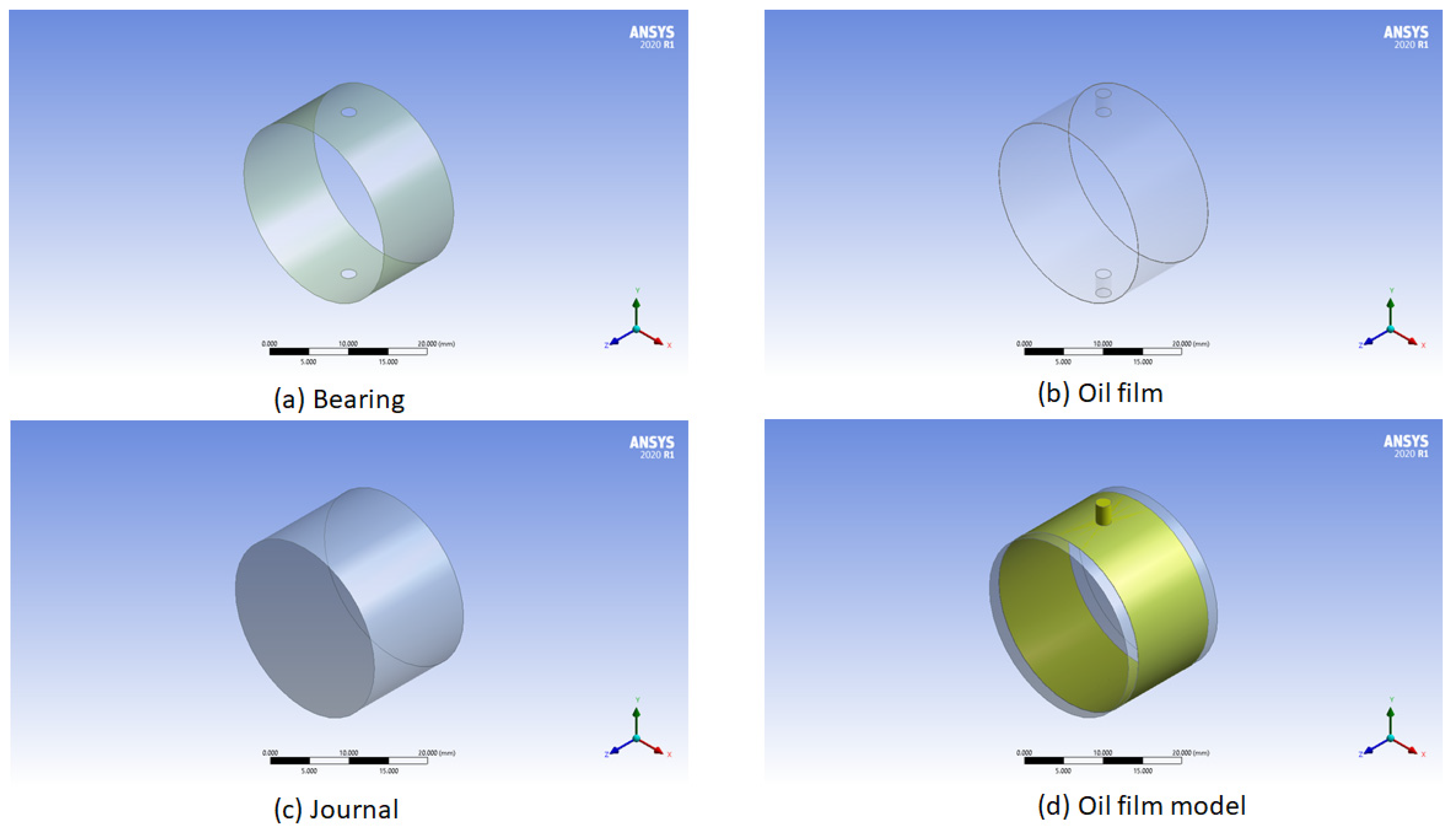
3.1. Geometrical Model

In this work, the journal bearing is modeled by taking the following design values. The short bearing assumption is used where L/d ≤ 0.5. In addition, the load applied on the shaft is in the form of a disk, as shown in Figure 1b. The specifications of the journal bearing test rig (JBTR) are given in Table 1.
Figure 1 shows a schematic diagram of the Journal Bearing Test Rig (JBTR). Figure 1a shows the highlighted area where the oil is supplied to the bearing and the oil film is formed, whereas Figure 1b shows the overall JBTR.
Figure 2 shows the simplified Ansys model for the fluid film model. Figure 2a represents the bearing, Figure 2b represents the oil film, Figure 2c represents the journal, and Figure 2d represents the overall model. In this way, the oil film model is developed. In the further discussion, only the oil film model is discussed for hydrodynamic pressure variation with temperature and viscosity.

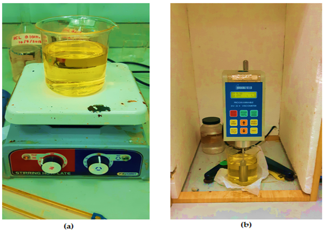
3.2. Dynamic Viscosity Measurement

Dynamic viscosity is the measure of the shear stress per unit area required before an oil sample begins to deform. Lubricants are characterized by their viscosity as a function of temperature, pressure, and shear rates. However, viscosity is largely influenced by the working temperature of the liquid [26]. The increase in temperature decreases the viscosity of the fluid. The viscosity of a liquid is measured using a device called a viscometer. In order to test the oil viscosity of the oil samples, the Brookfield Viscometer is used, as shown in Figure 3. The hot plate is used to heat the oil to the desired temperature, whereas the rotational viscometer is then used to measure the dynamic viscosity at the given temperature. ASTM standard D4402–02 is employed to carry out the procedure.
Table 2 shows some important properties of three bio-oils and SAE40 oil. Three bio-oils have almost similar flash points, which is almost 90 °C higher compared to that of SAE40. This is also an important factor when we consider that the operational range of machines is at higher temperatures, such as 120~200 °C [27]. Similarly, the density of bio-oils is also greater than that of SAE40 oil.

3.3. Computational Method

The Navier–Stokes equation, mass and momentum equation, and energy conservation equations are solved in steady-state, taking gravity forces into account. The model is established using ANSYS Fluent. The operating pressure is taken as an absolute 101,325 Pa at the inlet and 0 Pa at the outlet. In this work, the results are obtained by assuming a laminar flow. For the hydrodynamic pressure measurement for bio-oils and SAE40, the viscosity is not kept constant. Instead, the variable viscosity values are used, measured at different temperatures for different types of oils. The bearing shell is modeled as a stationary wall. The journal is modeled as a moving wall with a rotational speed of 3000 rpm. The rotational axis origin is set to the value of eccentricity. The lubricant inlet is modeled as pressure inlets and the lubricant outlet is modeled as pressure outlets. For greater accuracy, a convergence criterion of the order of 10−6 is used for all residual terms. The limitations for the Ansys fluent solver are that it uses constant viscosity unless the values are changed by the user.

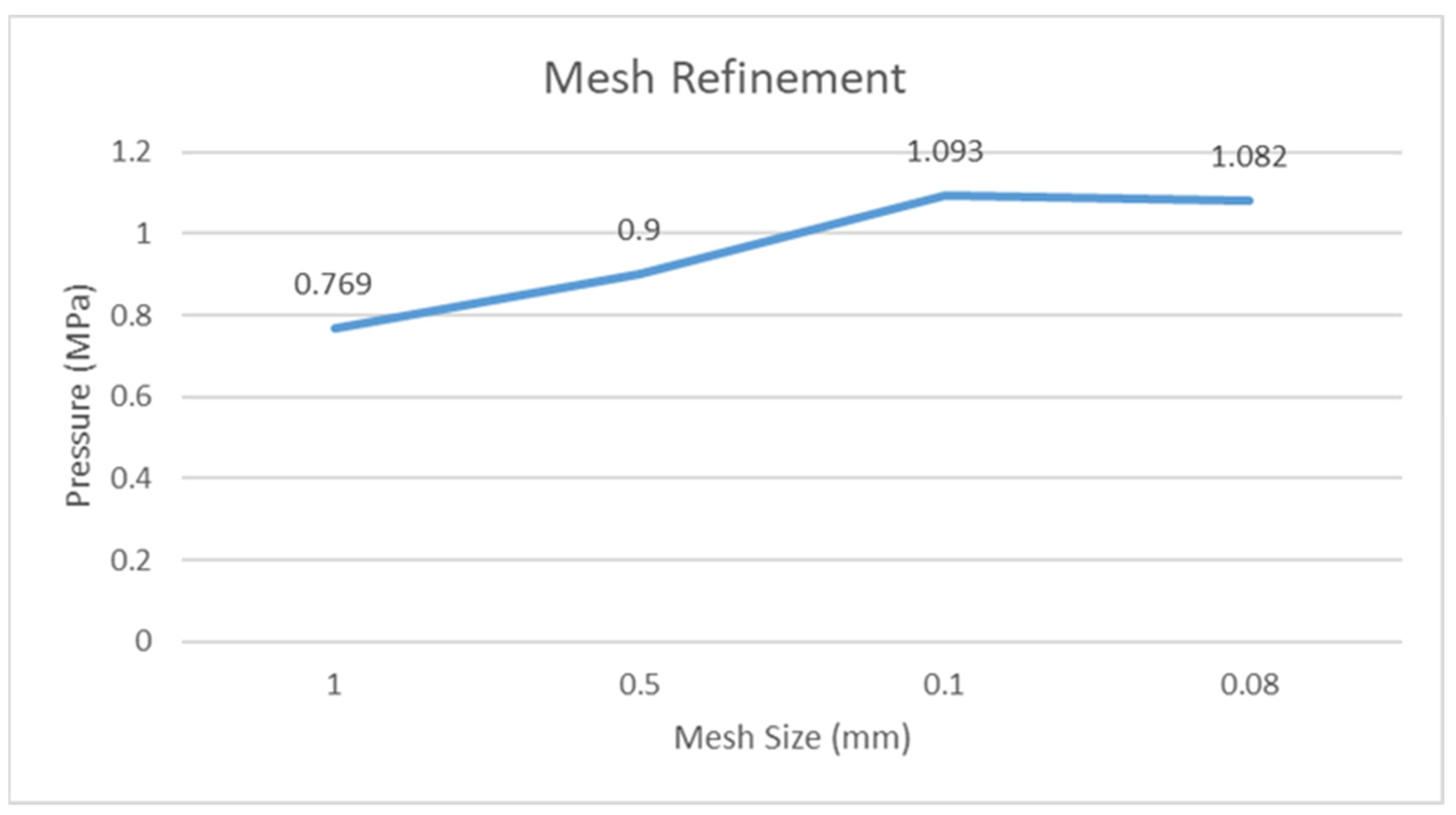
3.4. Mesh Refinement

Mesh refinement is carried out in order to obtain the accurate results of various parameters under consideration in ANSYS Fluent. At larger mesh size, the results are generally not accurate. As the mesh size decreases, the results tend to become more accurate, although the computational time also increases.
Figure 4 shows the pressure variation for different mesh sizes measured in ANSYS Fluent. As the mesh size becomes finer, the pressure value increases. At the same time after reaching the optimum value, the pressure does not increase any further. Thus, in this case, 0.1 mm is the value at which accurate results can be achieved. Further decreasing the mesh size from here on will only increase the burden on the computational system. As mentioned by [18], the increase in pressure is observed when the mesh refinement is carried out. An increase of approximately 30% in pressure is observed from a coarser mesh to a finer mesh.
Therefore, based on the dynamic viscosity values at different temperatures, the CFD technique is used for further evaluation of bio-oils and SAE40 for the hydrodynamic pressure distribution.

4. Results and Discussion

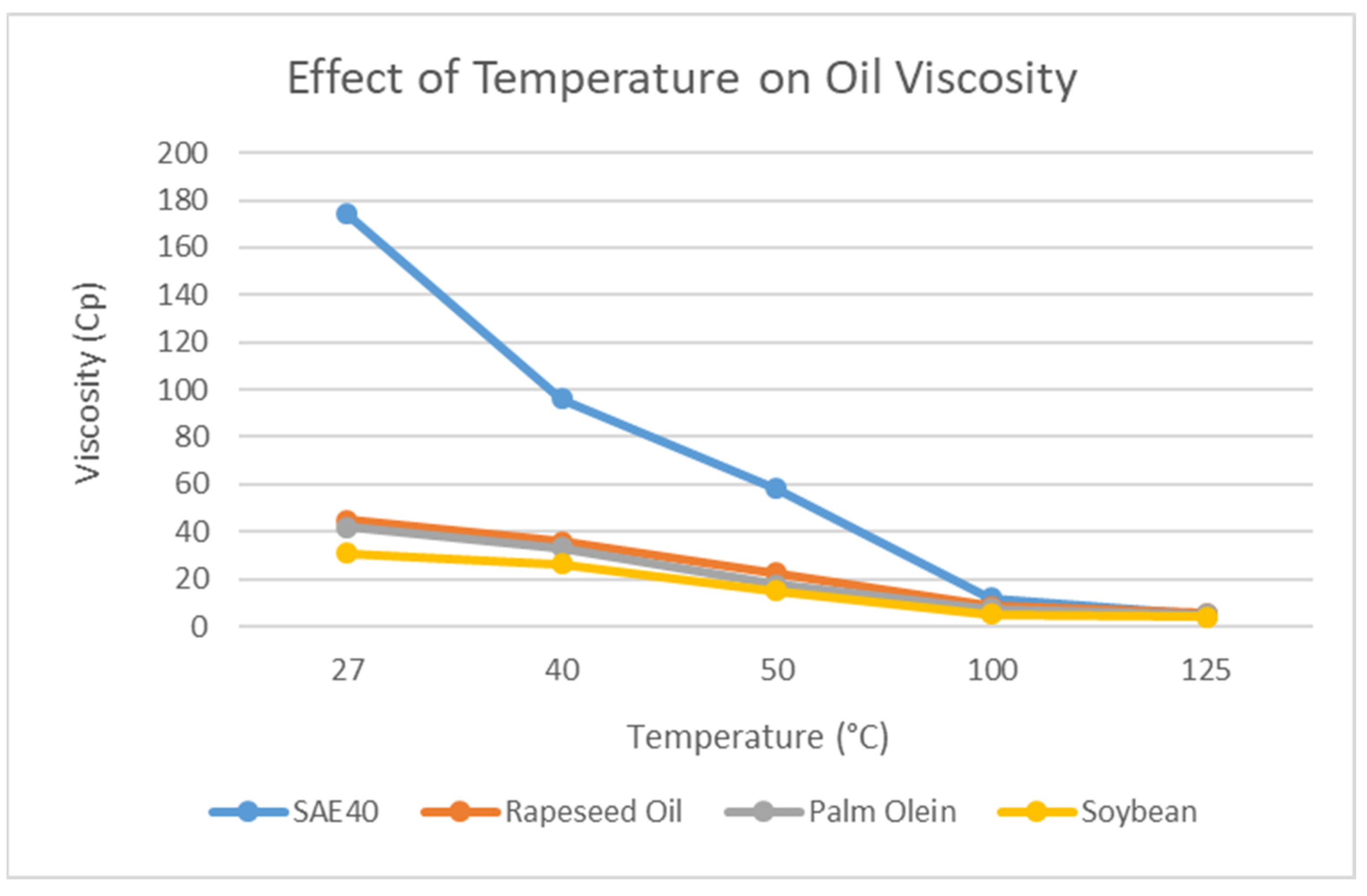
4.1. Effect of Temperature on Dynamic Viscosity

Increasing temperature has an effect on the dynamic viscosity of oils. As the temperature increases, the viscosity decreases. This is further elaborated in Figure 4 below.
The dynamic viscosity of the three types of bio-oils and SAE40 is measured from 27 °C to 25 °C. The experimental measurement of dynamic viscosity is performed using the viscometer. From Figure 5, we can see the effect of temperature on the dynamic viscosity of different types of oils. There is sharp decrease in viscosity observed for SAE40 from room temperature to 50 °C and from 50 °C to 100 °C, as reported by [29]. The behavior of three bio-oils is observed as quite similar with increasing temperature as the viscosity drop is much less compared to SAE40. In addition, the value of viscosity for SAE40 (4.8 cP) drops below those of rapeseed oil (5.3 cP) and palm olein (5 cP) at 125 °C. This is an important observation that leads to a drop in hydrodynamic pressure and load-carrying capacity of oil films at higher temperatures for SAE40.

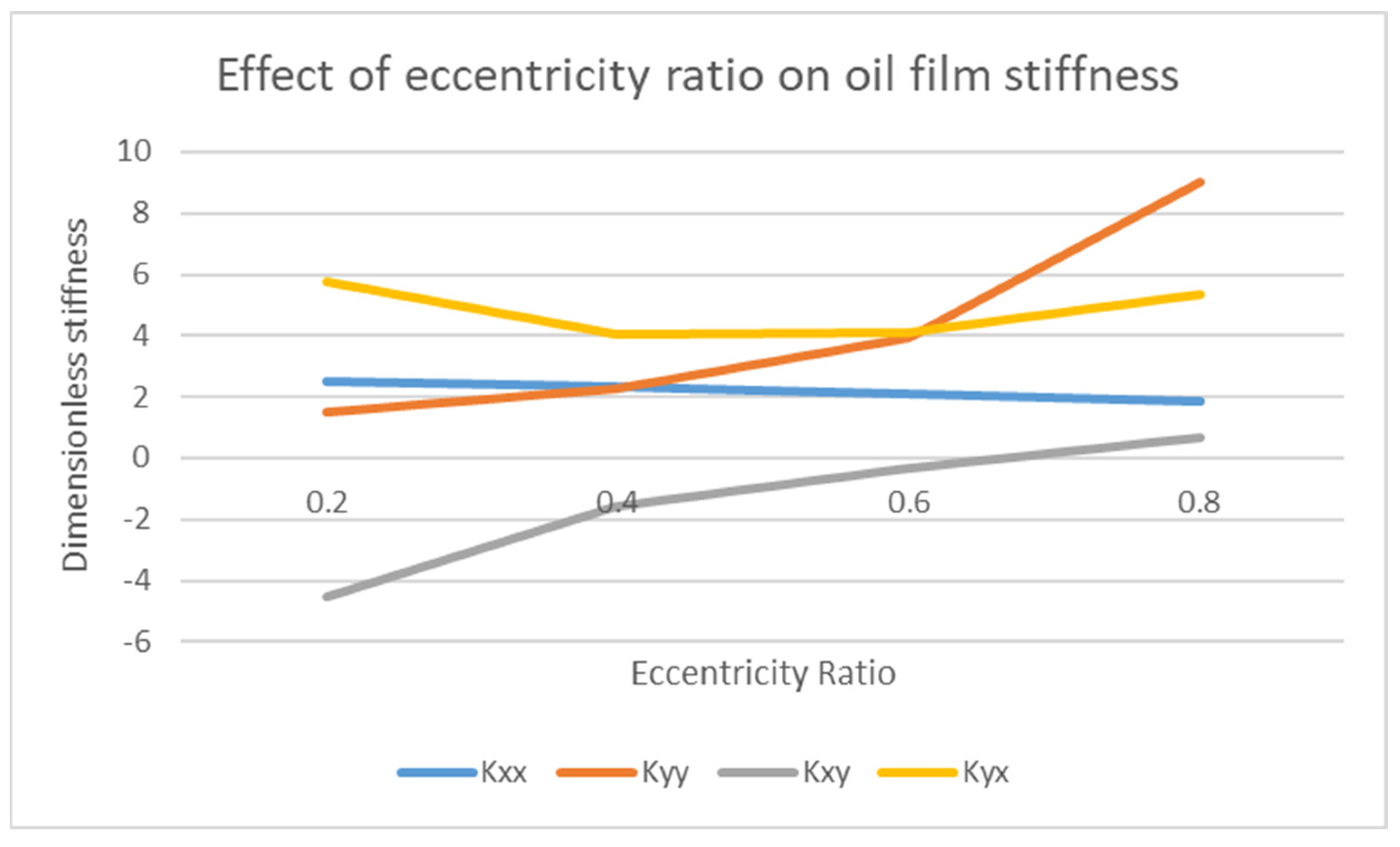
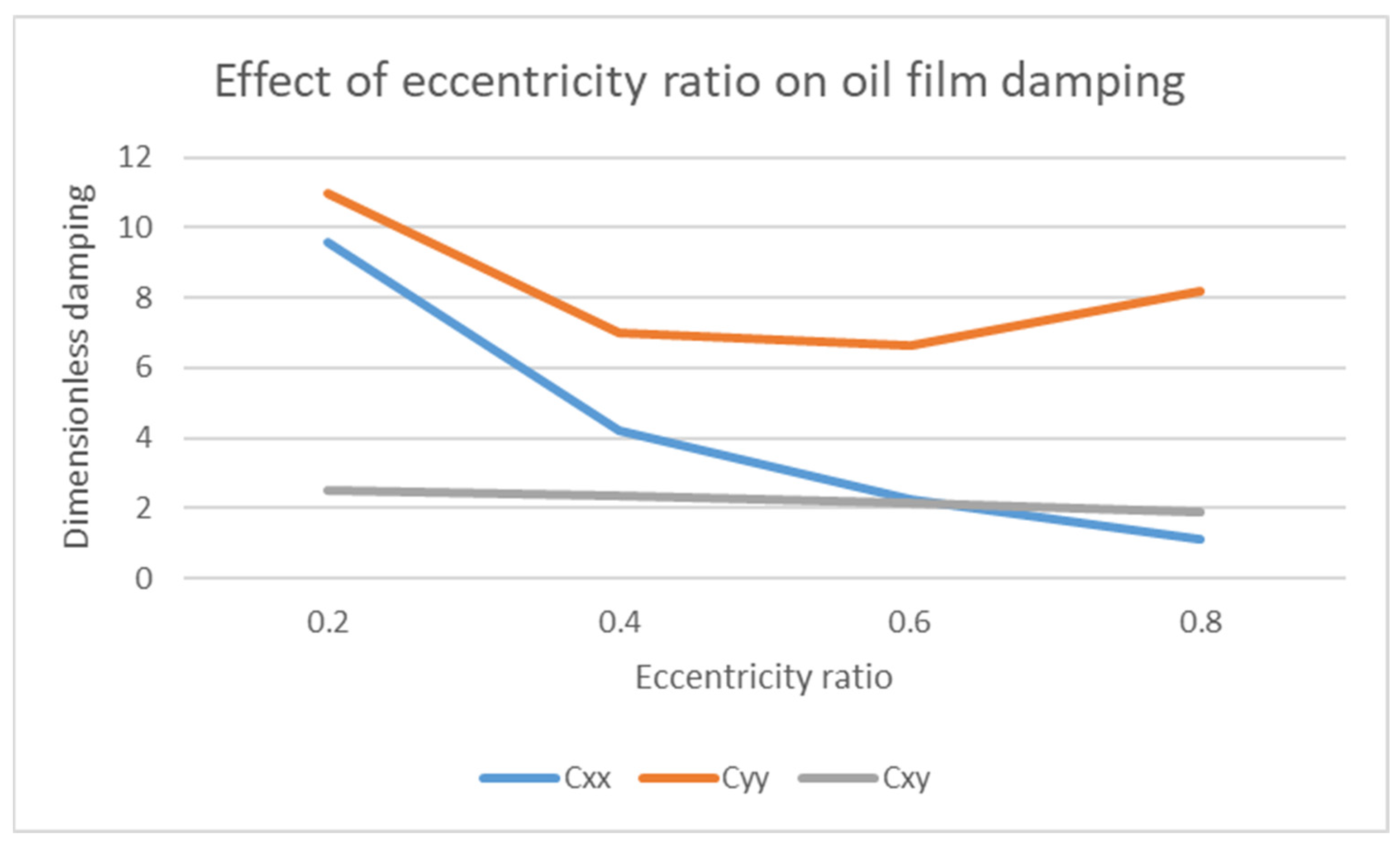
4.2. Effect of Eccentricity Ratio ε on Stiffness K and Damping C Coefficients

The eccentricity ratio also affects the stiffness and damping coefficients. The stiffness and damping coefficients play an important role in defining the dynamic response of the system. This is further explained in Figure 5 and Figure 6.
In Figure 6, the effect of eccentricity ratio against the dimensionless stiffness is plotted. All the four stiffnesses have different trends as the stiffnesses tend to vary for each dimension and condition. The cross-coupled stiffness terms Kxy and Kyx are the prime cause of rotordynamic instability. Therefore, it is very important to keep these terms as low as possible. The stiffness values are plotted for different eccentricity ratios. Depending on the condition of eccentricity ratio (load, rotational speed, length, and diameter), the concerned value of Kij can be used. The dimensionless stiffness coefficient Kij can be converted to dimensional stiffness coefficient kij by the given formula:
K i j = k i j   C W
where C is the radial clearance and W is the load on the bearing.
In Figure 7, the effect of eccentricity ratio against the dimensionless damping is plotted. For damping coefficients, Cxy and Cyx have the same value. The damping values are plotted for different eccentricity ratios. Depending on the condition of eccentricity ratio (load, rotational speed, length, and diameter), the relevant value of Cij can be used. The dimensionless damping coefficient Cij can be converted to dimensional damping coefficient cij by the given formula:
C i j = c i j   C   Ω W
where Ω is the rotational speed. The use of these eight stiffness and damping coefficient data values makes possible the determination of journal bearing characteristics on the stability of the rotor bearing system. The cross-coupled terms are the actual source of the dynamic instability effect in the rotating system. Therefore, these terms must be kept in the range of (0.4–0.6) for eccentricity ratio in order to obtain dynamic coefficients in the intermediate range, which is deemed as the safe range [30]. Another main point related to eccentricity ratio is that, if it is increased so that it approaches 1, the probability of self-excited vibrations (oil whirl and whip) also increases, as reported by [31].

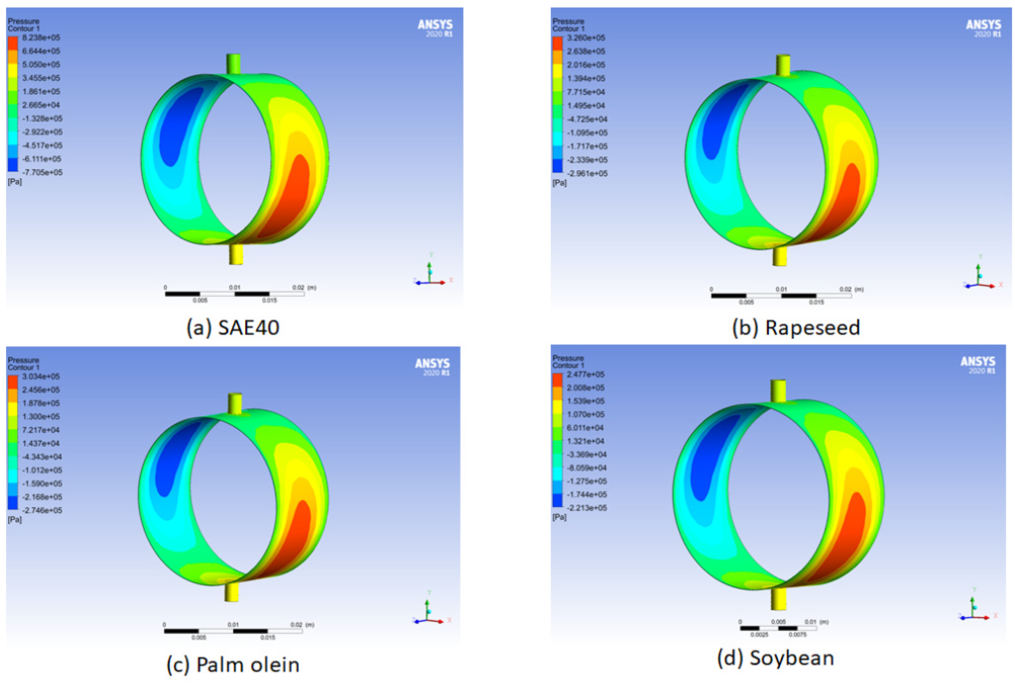
4.3. Numerical Analysis

Hydrodynamic pressure is measured for bio-oils and SAE40 under different operating conditions of temperature and viscosity using ANSY Fluent. This is further explained in the figures below.
From Figure 8, the hydrodynamic pressure distribution for bio-oils and SAE40 from the ANSYS Fluent post processing can be seen. Figure 8a gives the pressure distribution for SAE40. Similarly, Figure 8b–d show the pressure distribution of three bio-oils (rapeseed, palm olein, and soybean), respectively. For the pressure distribution on the bearing, the convergent oil wedge and divergent oil wedge can be seen in red and blue zones, respectively. It shows that the hydrodynamic pressure is higher for SAE40 at 40 °C compared to three bio-oils. This is further explained in Figure 9.
In Figure 9a,b, the maximum hydrodynamic pressure is compared between the bio-oils and SAE40. Figure 9a shows data at 40 °C whereas, Figure 9b shows data at 125 °C. The highest value of maximum hydrodynamic pressure is noted for SAE40 because of the high value of viscosity at a temperature of 40 °C. However, this value of maximum hydrodynamic pressure decreases for SAE40 at 125 °C. Hence, at a temperature of 125 °C, the load-carrying capacity also decreases due to the low viscosity for SAE40, as reported by [22].
Figure 10 gives the general trend of increasing speed of the journal on the hydrodynamic pressure using ANSYS Fluent. At low speed, due to the lubricant presence with suitable thickness, the bearing surface does not bear any pressure. As the speed of the journal increases, the hydrodynamic pressure also tends to increase for constant viscosity, and the bearing bears more pressure. This is also reported by [31,32]. This trend is observed when the viscosity is constant with increasing rotational speed of the journal, whereas, under actual operating conditions, this does not stand true. As the rotational speed of the journal increases, the viscosity also tends to decrease due to the increasing temperature of the lubricant. Thus, the trend shown in Figure 5 will be observed.
In Figure 11, the effect of viscosity can be seen on the hydrodynamic pressure. It is important to mention here that with the increasing temperature, the viscosity decreases. The four values at each temperature correspond to SAE40, rapeseed, palm olein, and soybean. From Figure 4, we obtain the response of viscosity variation as the temperature increases. The viscosity of SAE40 decreases sharply compared to the three bio-oils. It can be seen here that the effect of viscosity on pressure is quite similar to that in Figure 5. The rise in temperature decreases the dynamic viscosity, which ultimately decreases the hydrodynamic pressure and the load-carrying capacity of the oil film, as reported by [22]. At lower viscosity, the adjacent layers of the oil film are not too tightly bonded together, and they tend to shear more at lower viscosity as compared to the higher value of viscosity. Hence, the load-carrying capacity of the oil film also sees a decline at higher temperature as the loading-carrying capacity is also dependent on viscosity. From the CFD analysis, it is also observed that at higher temperatures, the hydrodynamic pressure response of bio-oils is better than that of SAE40. In addition, in order for bio-oils to be utilized for industrial applications for better physical and dynamic characteristics, additives need to be added in order to comply with the standards [33,34].
Overall, from the CFD results, rapeseed oil and palm olein have shown superior responses in comparison with SAE40, showing a lower decrease in viscosity and giving higher values of hydrodynamic pressure at higher temperatures. These oils can be specifically considered for applications where the steady-state temperature of the journal bearing oil film is above 100 °C.

5. Conclusions

Based on the CFD study to measure the hydrodynamic pressure response, bio-oils have shown a superior response. Similarly, from the results, it can be concluded that:
The dynamic viscosity drop is much less for bio-oils compared to SAE40. The stable behavior of bio-oils against the increasing temperature makes them suitable for high-temperature applications in journal bearings.
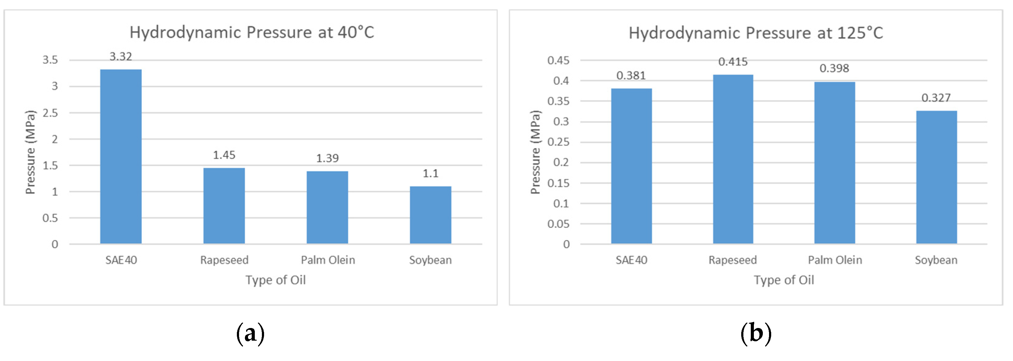
At 40 °C, the hydrodynamic pressure for SAE40 is observed to be 2.29, 2.39, and 3.01 times greater than those of rapeseed, palm olein, and soybean oil, respectively. Hence, the load-carrying capacity of oil film for SAE40 is also higher as the viscosity is higher compared to bio-oils.
By contrast, at 125 °C, the hydrodynamic pressure for SAE40 is observed to be 8% and 4.3% less than those of rapeseed and palm olein, respectively, but 14% greater than that of soybean oil. This decrease in hydrodynamic pressure causes the decline in load-carrying capacity of oil film for SAE40 compared to bio-oils.
Stiffness and damping coefficients are also investigated for different eccentricity ratios. Depending on the operating parameters (load, rotational speed, and viscosity), the value of eccentricity ratio can be calculated. The eccentricity ratio is important in evaluating the dynamic characteristics (stiffness and damping).
This shows how the temperature rise affects the performance of mineral-based lubricants more compared to bio-oils. Similarly, changing the eccentricity ratio also changes the stiffness and damping coefficients, which can have an effect on the dynamic stability of the system. Furthermore, the bio-lubricants used here are unprocessed compared to the mineral-based lubricant SAE40. The treatment of bio-oils according to operating conditions and requirements can also enhance their physical and dynamic properties.

Author Contributions

Conceptualization, M.I.S.; methodology, M.I.S. and W.A.W.G.; software, W.A.W.G., M.I.S. and M.R.R.; validation, M.I.S., W.A.W.G. and M.R.R.; formal analysis, M.I.S.; investigation, M.I.S.; resources, W.A.W.G., M.Z.N. and M.A.M.S.; data curation, W.A.W.G., M.I.S. and M.R.R.; writing—original draft preparation, M.I.S.; writing—review and editing, W.A.W.G., M.Z.N. and M.R.R.; visualisation, M.I.S.; supervision, W.A.W.G.; project administration, W.A.W.G.; funding acquisition, W.A.W.G., M.A.M.S. and M.Z.N. All authors have read and agreed to the published version of the manuscript.

Funding

The authors wish to show their gratitude to the Universiti Kebangsaan Malaysia (UKM) for its research funding GGPM-2021-008 and GUP-2019-019.

Institutional Review Board Statement

Not applicable.

Informed Consent Statement

Not applicable.

Data Availability Statement

Data are available upon request from the corresponding author. These data are not commercially available, due to privacy issues.

Acknowledgments

The authors would like to acknowledge Muhammad Hafizzuddin Bin Noorazzmy for his support in making the CAD drawings.

Conflicts of Interest

The authors declared no conflicts of interest and had no commercial or associative interests that represent a conflict of interest in connection with the research submitted.

Nomenclature

hoil film thickness
Cradial clearance
Nrotational speed
Ddiameter of bearing
Llength of bearing
Ppressure
Uvelocity of fluid
eeccentricity
ϕattitude angle
εeccentricity ratio
Kxx, Kyydimensionless direct stiffness
Kxy, Kyxdimensionless cross-coupled stiffness
Cxx, Cyydimensionless direct stiffness
Cxy, Cyxdimensionless cross-coupled stiffness

References

  1. San Andrés, L. Hydrodynamic Fluid Film Bearings and Their Effect on the Stability of Rotating Machinery. In Design and Analysis of High Speed Pumps; Educational Notes RTO-EN-AVT-143, Paper 10; RTO: Neuilly-sur-Seine, France, 2006; pp. 10-1–10-36. [Google Scholar]
  2. Gong, R.Z.; Li, D.Y.; Wang, H.J.; Han, L.; Qin, D.Q. Analytical solution of Reynolds equation under dynamic conditions. Proc. Inst. Mech. Eng. Part J J. Eng. Tribol. 2016, 230, 416–427. [Google Scholar] [CrossRef]
  3. Jamalabadi, M.Y.A. Effects of Nanoparticle Enhanced Lubricant Films in Dynamic Properties of Plain Journal Bearings at High Reynolds Numbers. Int. J. Eng. Technol. 2017, 13, 1–23. [Google Scholar] [CrossRef] [Green Version]
  4. Nikolic, N.; Antonic, Z.; Doric, J.; Ruzic, D.; Galambos, S.; Jocanovic, M.; Karanovic, V. An analytical method for the determination of temperature distribution in short journal bearing oil film. Symmetry 2020, 12, 539. [Google Scholar] [CrossRef] [Green Version]
  5. Sadiq, M.I.; Ghopa, W.A.W.; Nuawi, M.Z.; Rasani, M.R.M.; Imran, T. Effect of Bio Lubricants on the Dynamic Performance of Rotor Bearing System: A Mathematical Model. In Structural Integrity Cases in Mechanical and Civil Engineering; Abdullah, S., Karam Singh, S.S., Md Nor, N., Eds.; Springer International Publishing: Cham, Switzerland, 2022; pp. 195–207. [Google Scholar]
  6. Wang, K.; Wu, J.; Zhao, G. Numerical analysis of sliding bearing dynamic characteristics based on Numerical analysis of sliding bearing dynamic characteristics based on CFD. J. Phys. Conf. Ser. 2017, 916, 012025. [Google Scholar] [CrossRef] [Green Version]
  7. Tauviqirrahman, M.; Jamari, J.; Bayuseno, A.P. A comparative study of finite journal bearing in laminar and turbulent regimes using cfd (computational fluid dynamic). MATEC Web Conf. 2016, 4001, 10–13. [Google Scholar]
  8. Hosain, M.L.; Fdhila, R.B. Literature Review of Accelerated CFD Simulation Methods towards Online Application. Energy Procedia 2015, 75, 3307–3314. [Google Scholar] [CrossRef] [Green Version]
  9. Concli, F.; Gorla, C. Windage, churning and pocketing power losses of gears: Different modeling approaches for different goals. Forsch. Ing. 2016, 80, 85–99. [Google Scholar] [CrossRef]
  10. Hanoca, P.; Ramakrishna, H. V To Investigate the Effect of Oil Film Thickness at the Entrance of the Infinitely Long Slider Bearing Using CFD Analysis. Procedia Eng. 2015, 127, 447–454. [Google Scholar] [CrossRef] [Green Version]
  11. Chauhan, A.; Singla, A.; Panwar, N.; Jindal, P. CFD Based Thermo-Hydrodynamic Analysis of Circular Journal Bearing. Int. J. Adv. Mech. Eng. 2014, 4, 475–482. [Google Scholar]
  12. Manshoor, B.; Jaat, M.; Izzuddin, Z.; Amir, K. CFD Analysis of Thin Film Lubricated Journal Bearing. Procedia Eng. 2013, 68, 56–62. [Google Scholar] [CrossRef] [Green Version]
  13. Gertzos, K.P.; Nikolakopoulos, P.G.; Papadopoulos, C.A.Ã. CFD analysis of journal bearing hydrodynamic lubrication by Bingham lubricant. Tribol. Int. 2008, 41, 1190–1204. [Google Scholar] [CrossRef]
  14. Wang, C.; Morvan, H.P.; Hibberd, S.; Cliffe, K.A.; Anderson, A.; Jacobs, A. Specifying and Benchmarking a Thin Film Model for Oil Systems Applications in ANSYS Fluent. In Proceedings of the ASME Turbo Expo 2012: Turbine Technical Conference and Exposition, Copenhagen, Denmark, 11–15 June 2012; pp. 229–234. [Google Scholar]
  15. Ghani, J.A.; Mohd Nasir, F.F.; Rahman, H.A.; Hakim Wan Zamri, W.F.; Kasim, M.S.; Muhamad, S.S. Computational fluid dynamic analysis on tribological performance under hydrodynamic lubrication of dimple textured surface produced using turning process. Wear 2021, 477, 203898. [Google Scholar] [CrossRef]
  16. Mu, A.; Abdul, I.; Tantiyani, N.; Ali, B. Computational Fluid Dynamics Simulation of Fluidized Bed Dryer for Sago Pith Waste Drying Process Computational Fluid Dynamics Simulation of Fluidized Bed Dryer for Sago Pith Waste Drying Process. J. Kejuruter. 2021, 33, 239–248. [Google Scholar] [CrossRef]
  17. Ng, J. Computational fluid dynamics simulation on the heat sink performance of a graphics processing unit thermal management. J. Kejuruter. 2019, 31, 139–147. [Google Scholar] [CrossRef]
  18. Najar, F.A.; Harmain, G.A. Numerical Investigation of Pressure Profile in Hydrodynamic Lubrication Thrust Bearing. Int. Sch. Res. Not. 2014, 2014, 1–8. [Google Scholar] [CrossRef] [Green Version]
  19. Nowak, P.; Kucharska, K.; Kamiński, M. Ecological and Health Effects of Lubricant Oils Emitted into the Environment. Int. J. Environ. Res. Public Health 2019, 16, 3002. [Google Scholar] [CrossRef] [Green Version]
  20. Syahir, A.Z.; Zulkifli, N.W.M.; Masjuki, H.H.; Kalam, M.A.; Alabdulkarem, A.; Gulzar, M.; Khuong, L.S.; Harith, M.H. A review on bio-based lubricants and their applications. J. Clean. Prod. 2017, 168, 997–1016. [Google Scholar] [CrossRef]
  21. Trzepieciński, T. Tribological performance of environmentally friendly bio-degradable lubricants based on a combination of boric acid and bio-based oils. Materials 2020, 13, 3892. [Google Scholar] [CrossRef]
  22. Li, L.; Liu, Z.; Wang, C.; Xie, Y. Influence of temperature effect on the static and dynamic performance of gas-lubricatedmicrobearings. Micromachines 2020, 11, 716. [Google Scholar] [CrossRef]
  23. Sun, D.; Li, S.; Fei, C.; Ai, Y.; Liem, R.P. Investigation of the effect of cavitation and journal whirl on static and dynamic characteristics of journal bearing. J. Mech. Sci. Technol. 2019, 33, 77–86. [Google Scholar] [CrossRef]
  24. Hmoad, N. Effect of Using the Biolubricant Oil on the Dynamic Performance of Journal Bearings. Int. J. Mech. Mechatron. Eng. 2020, 20, 77–84. [Google Scholar]
  25. He, M.; Cloud, C.H.; Byrne, J.M.; Vázquez, J.A. Fundamentals of Fluid Film Journal Bearing Operation and Modeling. In Proceedings of the 34th Turbomachinery Conference 2005, Houston, TX, USA, 12–15 December 2005. [Google Scholar]
  26. Wan Nik, W.B.; Ani, F.N.; Masjuki, H.H.; Eng Giap, S.G. Rheology of bio-edible oils according to several rheological models and its potential as hydraulic fluid. Ind. Crops Prod. 2005, 22, 249–255. [Google Scholar] [CrossRef]
  27. Wróblewski, P. Analysis of Torque Waveforms in Two-Cylinder Engines for Ultralight Aircraft Propulsion Operating on 0W-8 and 0W-16 Oils at High Thermal Loads Using the Diamond-Like Carbon Composite Coating. SAE Int. J. Engines 2021, 15, 8–11. [Google Scholar] [CrossRef]
  28. Sadiq, M.I.; Ghopa, W.A.; Nuawi, M.Z.; Rasani, M.R. An Experimental Investigation of Static Properties of Bio-Oils. Materials 2022, 15, 2247. [Google Scholar] [CrossRef]
  29. Hoang, A.T.; Pham, M.T. Influences of heating temperatures on physical properties, spray characteristics of bio-oils and fuel supply system of a conventional diesel engine. Int. J. Adv. Sci. Eng. Inf. Technol. 2018, 8, 2231–2240. [Google Scholar] [CrossRef]
  30. Lee, C.W. Vibration Analysis of Rotors; Springer: Berlin/Heidelberg, Germany, 1994; Volume 208, ISBN 9789048142804. [Google Scholar]
  31. Hekmat, M.H.; Biukpour, G.A. Numerical study of the oil whirl phenomenon in a hydrodynamic journal bearing. J. Braz. Soc. Mech. Sci. Eng. 2019, 41, 218. [Google Scholar] [CrossRef]
  32. Du, F.; Chen, C.; Zhang, K. Fluid Characteristics Analysis of the Lubricating Oil Film and the Wear Experiment Investigation of the Sliding Bearing. Coatings 2022, 12, 67. [Google Scholar] [CrossRef]
  33. Encinar, J.M.; Nogales-Delgado, S.; Sánchez, N.; González, J.F. Biolubricants from rapeseed and castor oil transesterification by using titanium isopropoxide as a catalyst: Production and characterization. Catalysts 2020, 10, 366. [Google Scholar] [CrossRef] [Green Version]
  34. Nuawi, M.Z. Mesokurtosis Zonal Nonparametric signal analysis for dynamic characterisation of metallic material. J. Kejuruter. 2012, 24, 21–27. [Google Scholar]
Figure 1. (a) Journal bearing schematic; (b) overall diagram of Journal Bearing Test Rig (JBTR).
Materials 15 03595 g001
Figure 2. Ansys oil film model.
Materials 15 03595 g002
Figure 3. (a) Hot plate; (b) Viscometer for viscosity measurement.
Materials 15 03595 g003
Figure 4. Effect of mesh size on the maximum hydrodynamic pressure (ANSYS Fluent).
Materials 15 03595 g004
Figure 5. Effect of temperature on oil viscosity.
Materials 15 03595 g005
Figure 6. Effect of eccentricity ratio ε on dimensionless stiffness K.
Materials 15 03595 g006
Figure 7. Effect of eccentricity ratio ε on dimensionless damping C.
Materials 15 03595 g007
Figure 8. Hydrodynamic pressure distribution.
Materials 15 03595 g008
Figure 9. Comparison of maximum hydrodynamic pressure.
Materials 15 03595 g009
Figure 10. Effect of RPM on hydrodynamic pressure (ANSYS Fluent).
Materials 15 03595 g010
Figure 11. Pressure variation with variable viscosity.
Materials 15 03595 g011
Table 1. Specifications of the Journal Bearing Test Rig (JBTR).
NoDescriptionSpecification
1L, bearing length12.5 mm
2D, inner diameter for plain bearing25.14 mm
3d, shaft diameter25 mm
4Weight of journal9 N
5W, Weight of load25 N
6CT, total clearance0.14 mm
7C, radial clearance0.07 mm
8ε, Eccentricity ratio 0.2–0.8
9L/d ratio (short bearing assumption)0.5
10Operating speed1000~3000 rpm
Table 2. Physical properties of oil samples [28].
PropertiesSAE40Palm OleinRapeseedSoya Bean
Flash point (°C)235324326330
Specific heat, Cp (kJ/kg·C)2.531.91.961.88
Thermal conductivity (W/m·C)0.1450.1720.1680.185
Density at 15 °C (g/cm3)0.8900.9120.9150.924
Publisher’s Note: MDPI stays neutral with regard to jurisdictional claims in published maps and institutional affiliations.

