
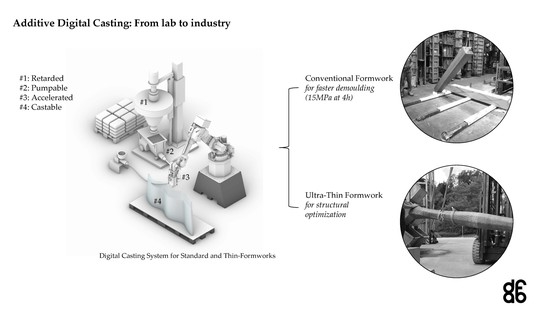
Additive Digital Casting: From Lab to Industry

 ,
,  , ,
, ,
Abstract
:
1. Introduction
2. Background and Requirements
2.1. Upscaling Concrete Processes
2.2. Inline Laboratory Reactor for Setting on Demand
2.3. Reference Conditions of Industrial Prefabrication
2.4. Specific Requirements for Material and Structures
- Final properties
- 90 MPa after 28 days (strength class C75/90);
- Fire approved in accordance with standard European building codes;
- Up to 3 m tall columns with cross sections ranging from 30 × 30 cm to 50 × 50 cm;
- Good surface quality (smooth, closed and largely uniform);
- Similar price to the industrial reference.
- Processing
- Castable in less than 10 min.
- Material before acceleration
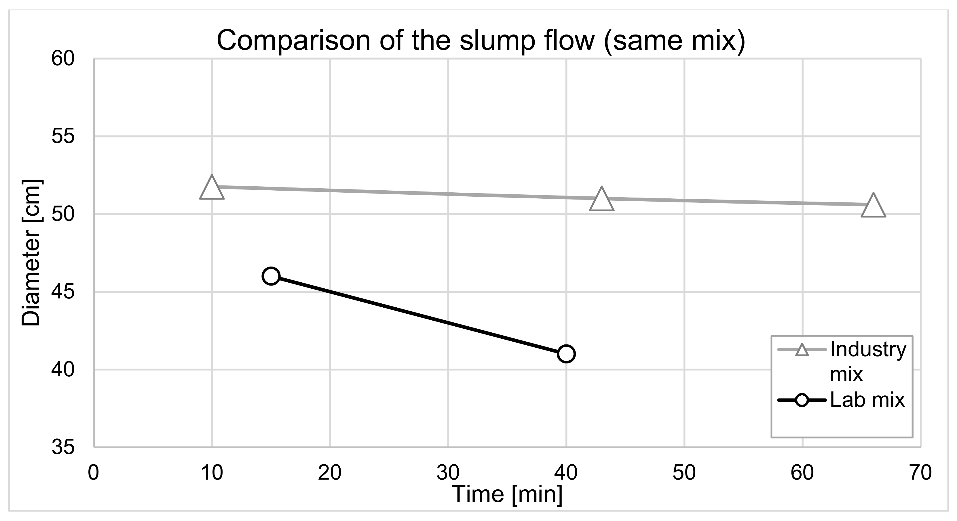
- Good flowability over a sufficient time (e.g., slump flow of 50–60 cm not changing more than 5 cm over 4 h).
- Material after acceleration
- Reach 15 MPa within 4 h;
- For ordinary formworks: pumpable for at least 10 min after acceleration;
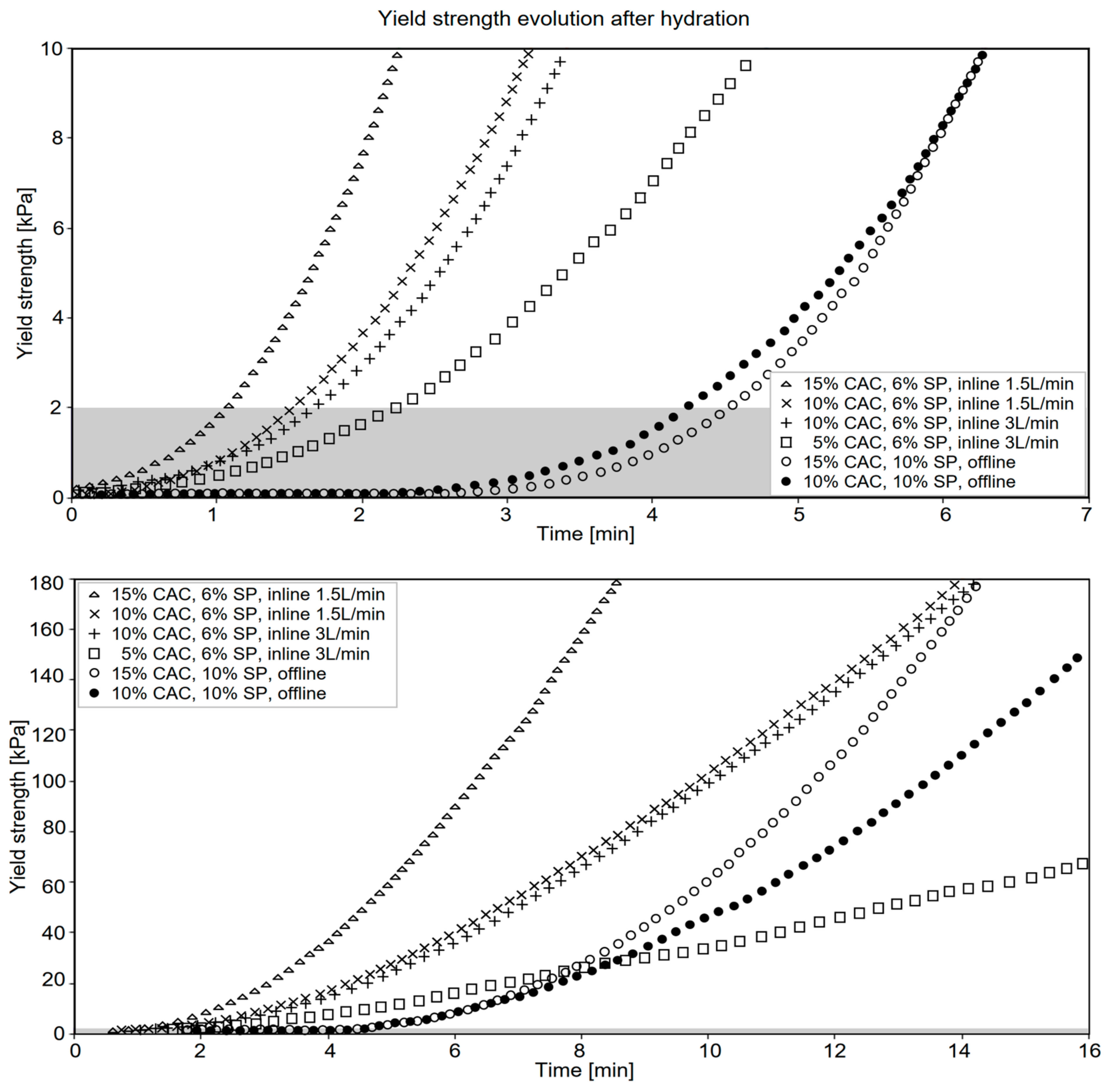
- For weak formwork: rapid setting of 2 kPa yield stress 1–2 min after acceleration.
- Increasing the aggregate size from 4 mm to 8 mm (reducing the paste content);
- Including short polypropylene fibers (to obtain fire resistance);
- Changing the cement supplier (cement available at the company in question);
- Increasing cement replacement by limestone (lower cost, heat release and CO2 footprint);
- Developing a faster and more robust acceleration system (higher industrial performance).
3. Materials and Methods
3.1. Materials
3.2. Test Methods
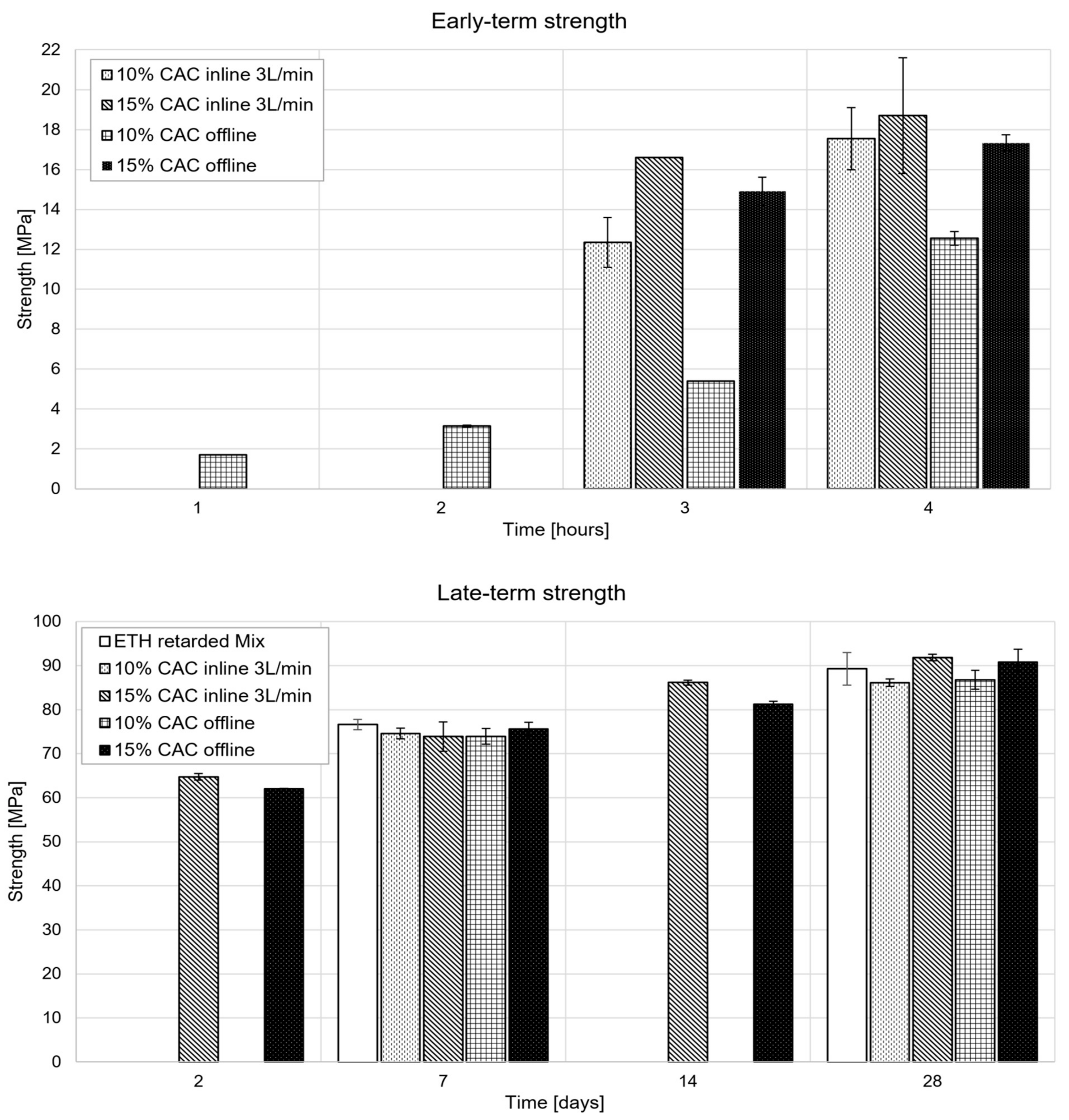
- The second period refers to the demolding strength and is determined by a standard compressive strength measurement (BS EN 12390-3 with a force-controlled mode set at 0.96 kN/s) of 15 cm cubic samples. For this paper, a demolding strength of 15 MPa was targeted at 4 h.
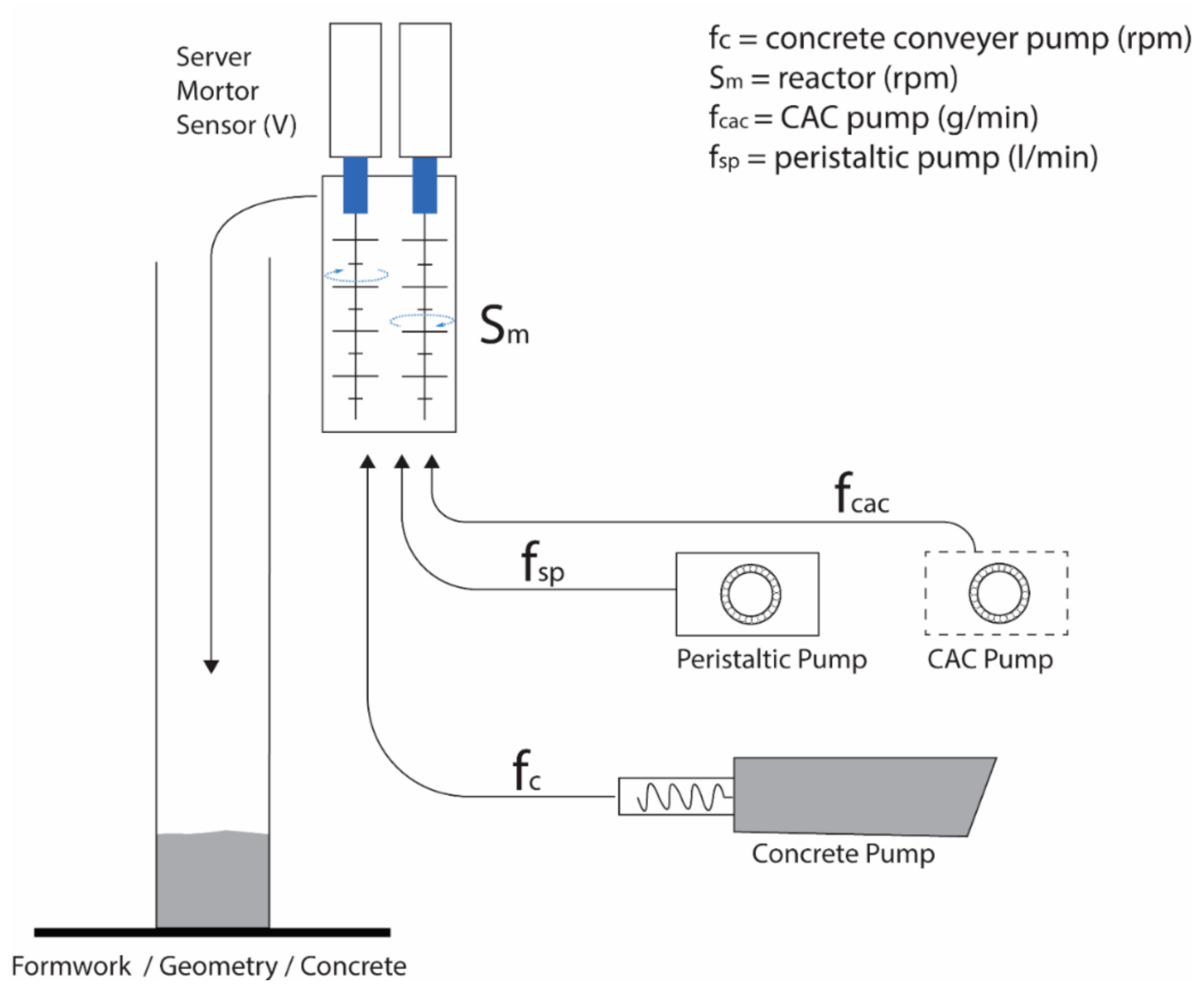
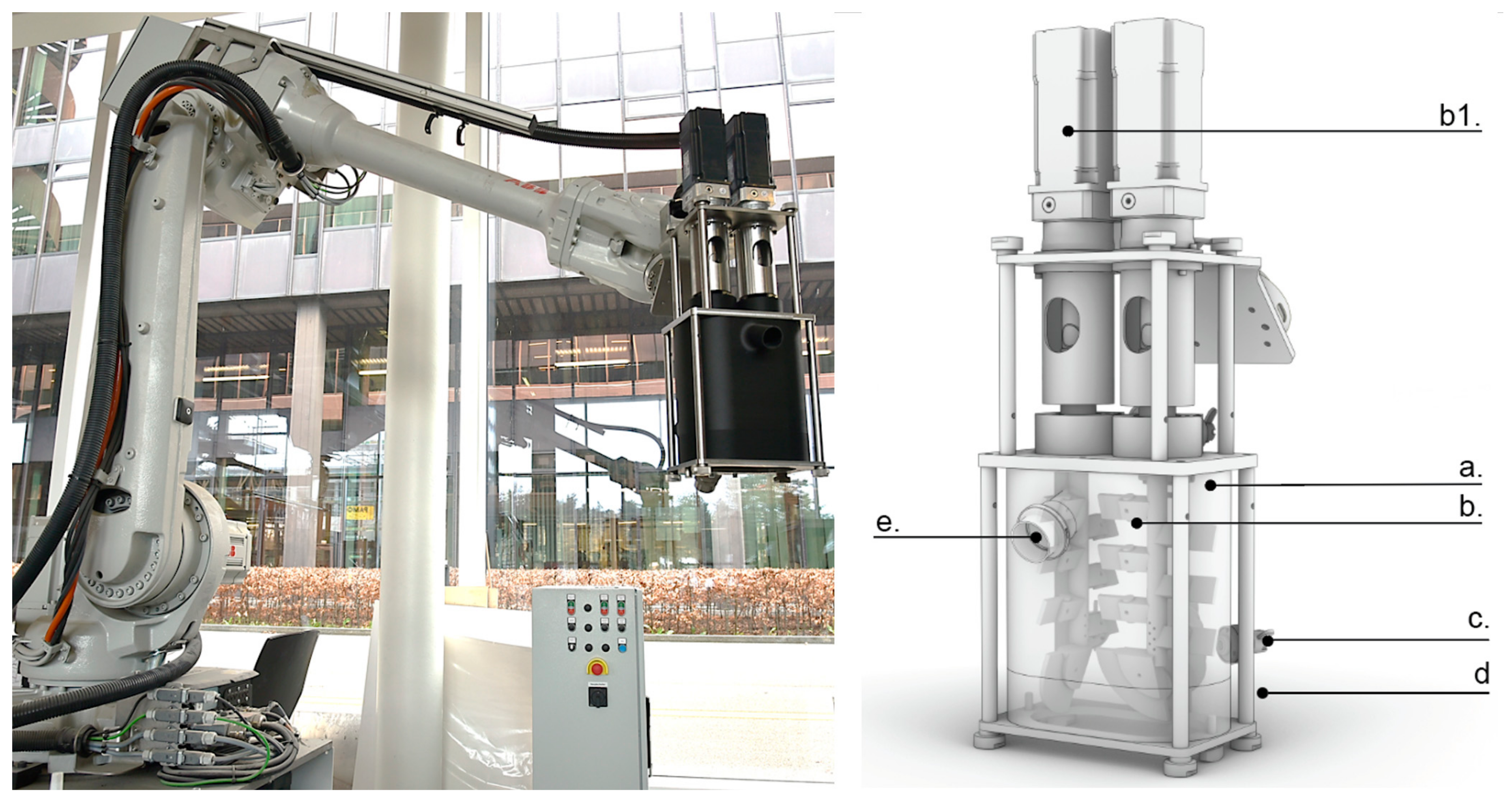
3.3. Processing System
- Change from a discontinuous to a continuous pumping system, which means slow pumping rates can be controlled without starting and stopping the system. This required changing the minimum rotation of the motor of the PFT SWING L Pump from 454 to 46 rotations per minute (RPM).
- Change the mixing reactor from an open funnel to a closed non-pressurized system (both 1 and 2 were done to prevent backflow).
- Change the dimensions of the reactor from a single-pin to a double-pin mixing system to increase mixing energy and to have the possibility to mix aggregates up to 8 mm.
- Change motors from asynchrony motor to server motors in order to:
- Reduce the weight of the mixing unit.
- Increase flexibility in the mixing control (back and forth mixing) and individually control impellers.
- Record the resistance of the motors in voltage (V), which gives an indication of the viscosity of the mixture and can be used in a feedback loop to regulate the mixing rate on the fly during production. This measurement though reflects a high-shear behavior, while concrete placing is a low-shear process. Therefore, this sensor only offers limited insight into yield stress, which is the rheological property of greatest interest, but can nevertheless be used to monitor the consistency of the mixture.
- Change control software from an open-loop control system to a closed-loop control system.
4. Material Development and Prototyping
4.1. Material
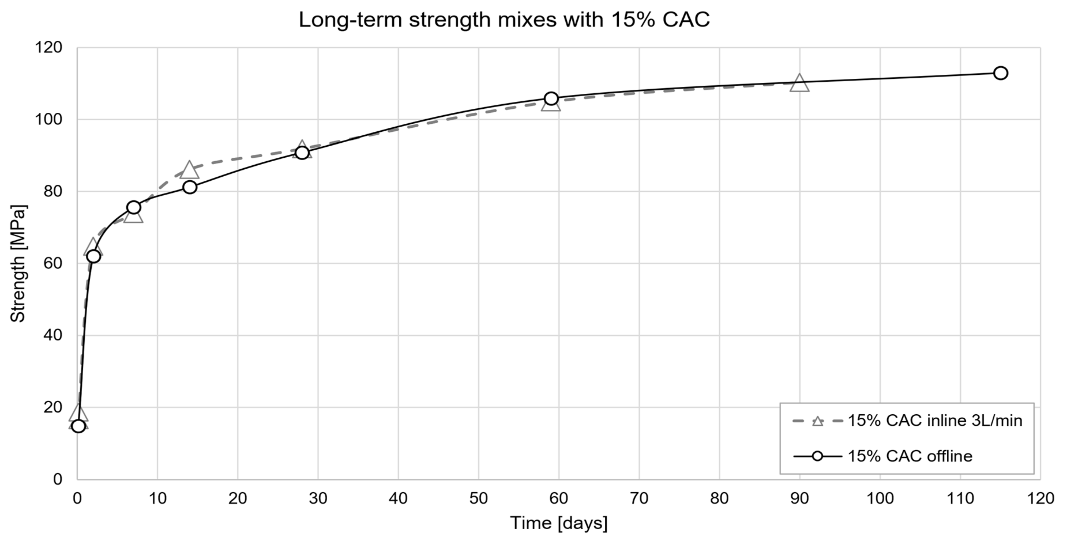
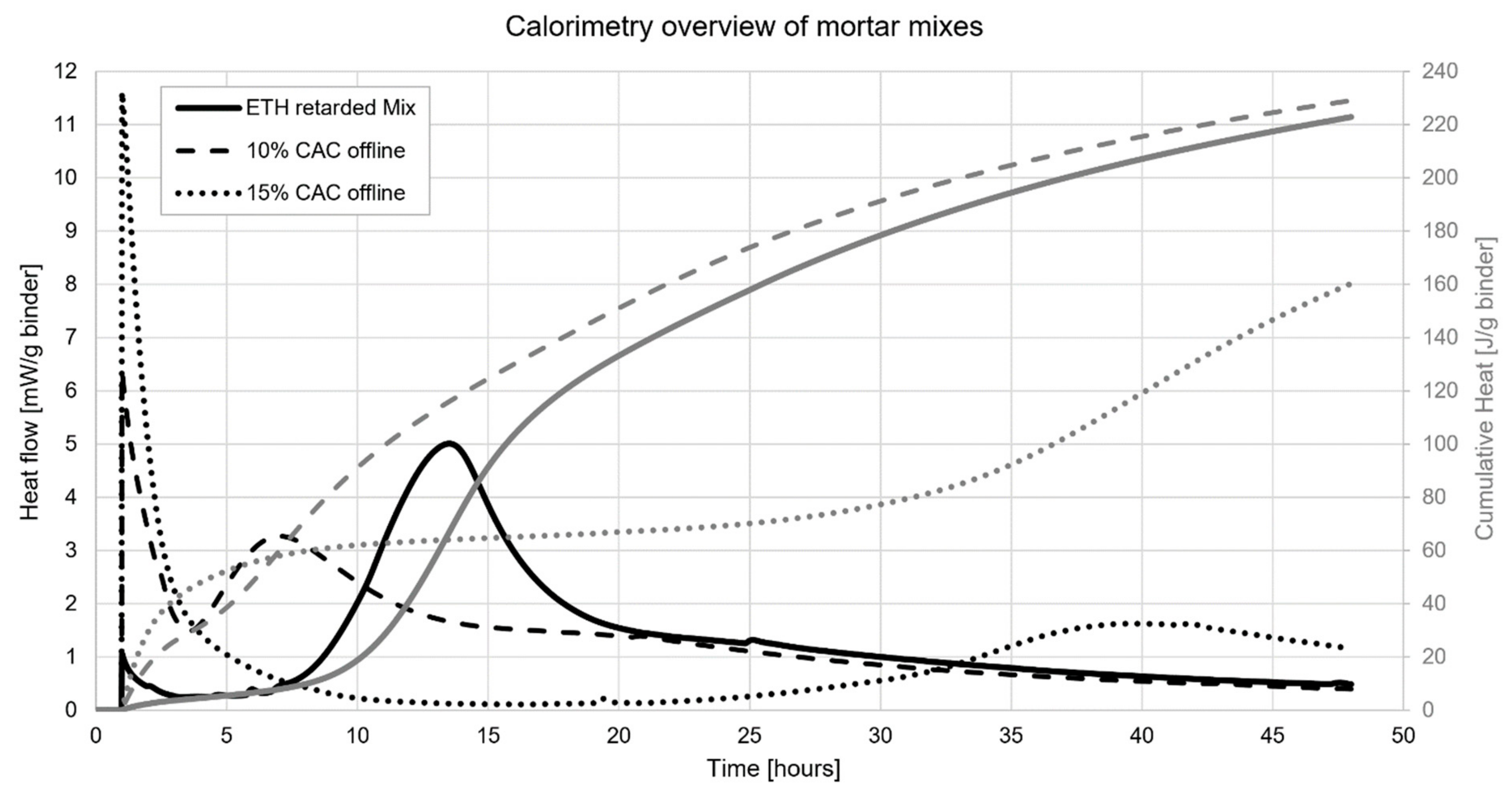
4.1.1. Strength Development
4.1.2. Setting Control
4.2. Prototyping
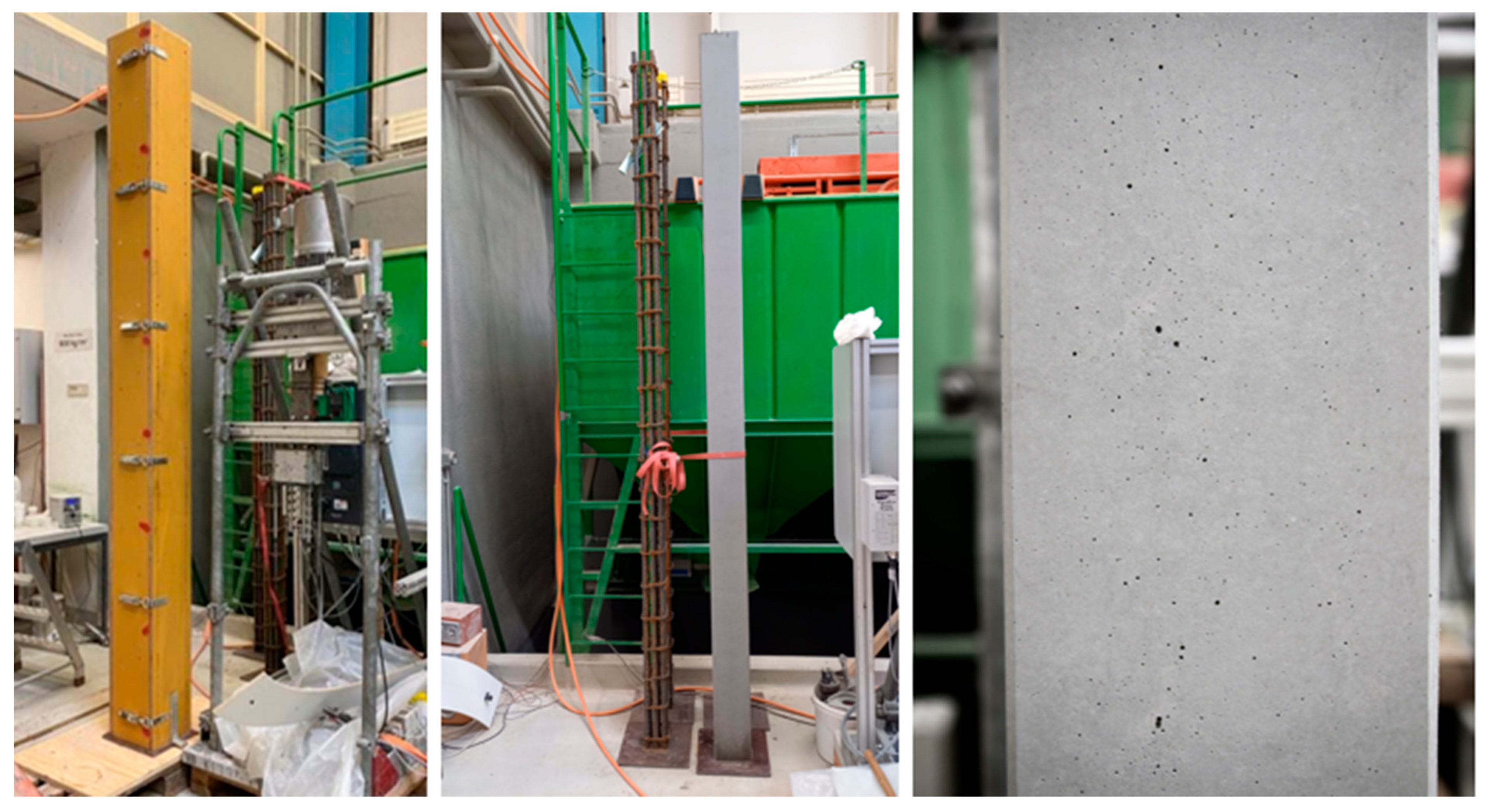
4.2.1. Casting in Standard Formwork
- The element could be demolded after 4 h (having reached 15 MPa).
- The surface quality is very good (Figure 9 Right), although it still falls short of the SIA norm for exposed concrete.
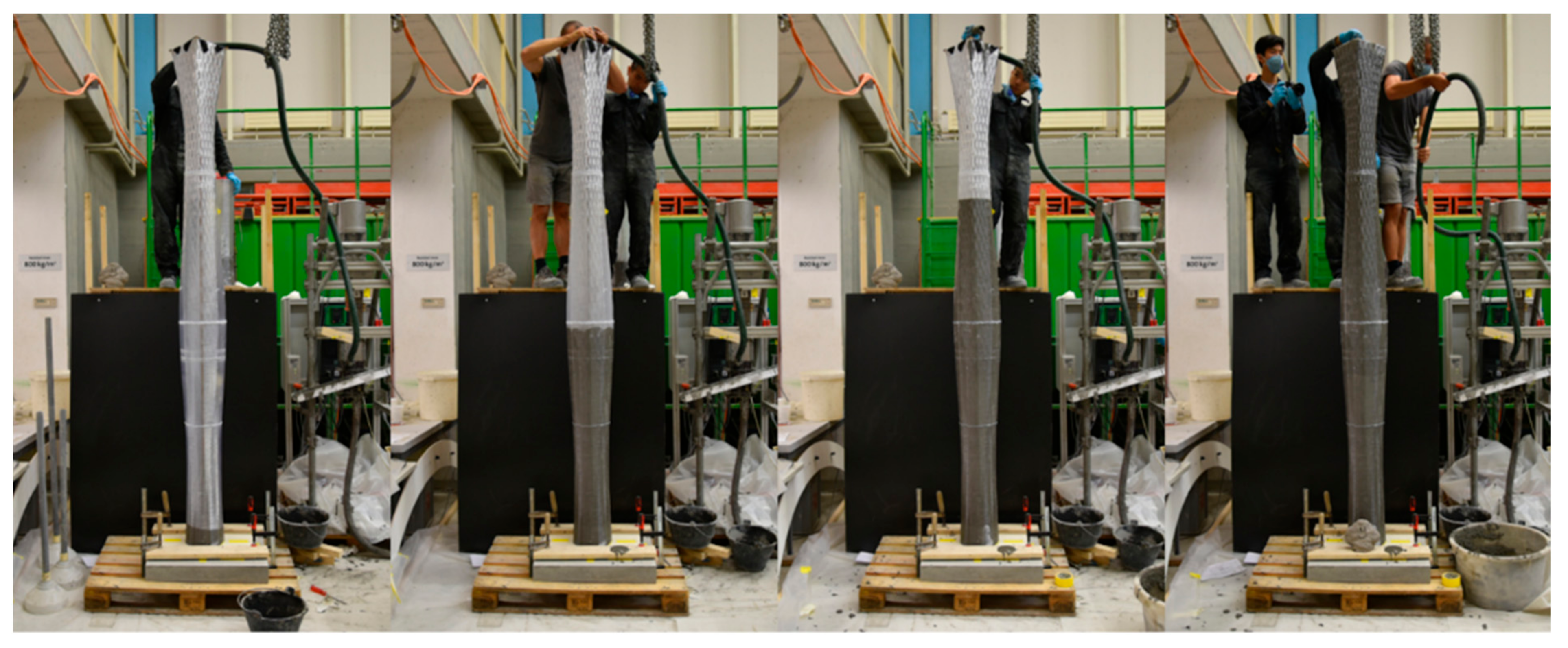
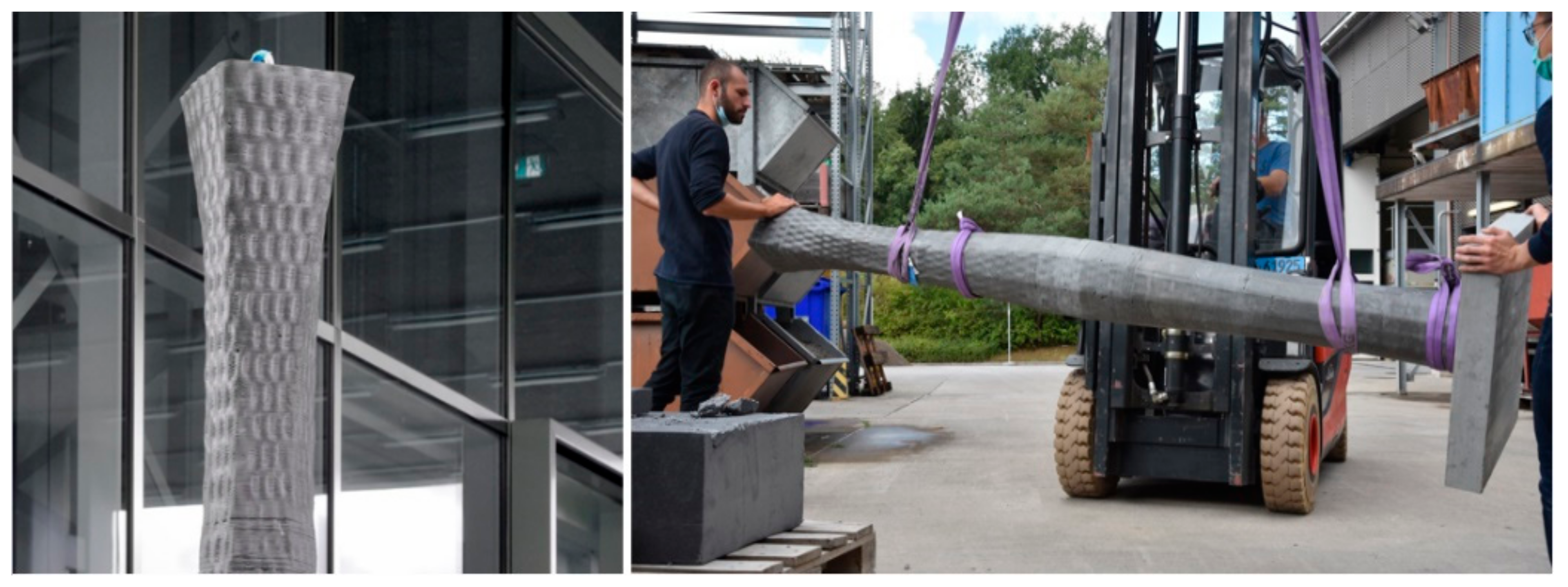
4.2.2. Casting in Non-Standard Formwork
4.3. Overview of Results from Experiments to Benchmark in Industry
5. General Discussion
5.1. Materials Issues
5.2. Processing
5.3. Prototypes
6. Conclusions
Supplementary Materials
Author Contributions
Funding
Institutional Review Board Statement
Informed Consent Statement
Acknowledgments
Conflicts of Interest
References
- Szabo, A.; Reiter, L.; Lloret-fritschi, E.; Gramazio, F.; Kohler, M.; Flatt, R.J. Processing of set on demand solutions for digital fabrication in architecture. In Proceedings of the 2nd International Conference on Rheology and Processing of Construction Materials, Eindhoven, The Netherlands, 12–15 August 2019; pp. 1–8. [Google Scholar]
- Reiter, L.; Wangler, T.; Anton, A.; Flatt, R.J. Setting on demand for digital concrete – Principles, measurements, chemistry, validation. Cem. Concr. Res. 2020, 132, 106047. [Google Scholar] [CrossRef]
- Lloret, E.; Shahab, A.R.; Linus, M.; Flatt, R.J.; Gramazio, F.; Kohler, M.; Langenberg, S. Complex concrete structures: Merging existing casting techniques with digital fabrication. Comput. Aided Des. 2015, 60, 40–49. [Google Scholar] [CrossRef]
- Anton, A.; Bedarf, P.; Yoo, A.; Dillenburger, B.; Reiter, L.; Wangler, T.; Flatt, R.J. Concrete Choreography: Prefabrication of 3D-Printed Columns. In Proceedings of the Fabricate 2020: Making Resilient Architecture, Online, 9–12 September 2020; Burry, J., Sabin, J., Sheil, B., Skavara, M., Eds.; UCL Press: London, UK, 2020; pp. 286–293. [Google Scholar]
- Boscaro, F.; Quadranti, E.; Wangler, T.; Mantellato, S.; Reiter, L.; Flatt, R.J. Eco-Friendly, Set-on-Demand Digital Concrete. 3d Print. Addit. Manuf. 2022, 9, 3–11. [Google Scholar] [CrossRef]
- Wangler, T.; Lloret, E.; Reiter, L.; Hack, N.; Gramazio, F.; Kohler, M.; Bernhard, M.; Dillenburger, B.; Buchli, J.; Roussel, N.; et al. Digital Concrete: Opportunities and Challenges. RILEM Tech. Lett. 2016, 1, 67–75. [Google Scholar] [CrossRef]
- Marchon, D.; Kawashima, S.; Bessaies-Bey, H.; Mantellato, S.; Ng, S. Hydration and rheology control of concrete for digital fabrication: Potential admixtures and cement chemistry. Cem. Concr. Res. 2018, 112, 96–110. [Google Scholar] [CrossRef]
- SIKA Sika Highspeed 3D Printing. Available online: https://www.youtube.com/watch?v=oiSFLQWTg7k (accessed on 9 October 2019).
- Buswell, R.A.; Leal de Silva, W.R.; Jones, S.Z.; Dirrenberger, J. 3D printing using concrete extrusion: A roadmap for research. Cem. Concr. Res. 2018, 112, 37–49. [Google Scholar] [CrossRef]
- Thongkamsuk, P.; Sudasna, K.; Tondee, T. Waste generated in high-rise buildings construction: A current situation in Thailand. Energy Procedia 2017, 138, 411–416. [Google Scholar] [CrossRef]
- Poulikakos, L.D.; Papadaskalopoulou, C.; Hofko, B.; Gschösser, F.; Cannone Falchetto, A.; Bueno, M.; Arraigada, M.; Sousa, J.; Ruiz, R.; Petit, C.; et al. Harvesting the unexplored potential of European waste materials for road construction. Resour. Conserv. Recycl. 2017, 116, 32–44. [Google Scholar] [CrossRef]
- Construction and Demolition Waste: Challenges and Opportunities in a Circular Economy—European Environment Agency. Available online: https://www.eea.europa.eu/themes/waste/waste-management/construction-and-demolition-waste-challenges (accessed on 1 February 2021).
- Boscaro, F. Research Driven New Low Clinker Activated Blended Cements. Ph.D. Thesis, ETH Zurich, Zürich, Switzerland, 2020. [Google Scholar]
- Burger, J.; Lloret-Fritschi, E.; Taha, N.; Scotto, F.; Demoulin, T.; Mata-Falcón, J.; Gramazio, F.; Kohler, M.; Flatt, R.J. Design and Fabrication of a Non-standard, Structural Concrete Column Using Eggshell: Ultra-Thin, 3D Printed Formwork. In Proceedings of the Second RILEM International Conference on Concrete and Digital Fabrication, Eindhoven, The Netherlands, 6–8 July 2020; Bos, F.P., Lucas, S.S., Wolfs, R.J.M., Salet, T.A.M., Eds.; Springer International Publishing: Cham, Switzerland, 2020; pp. 1104–1115. [Google Scholar]
- Lloret-Fritschi, E.; Wangler, T.; Gebhard, L.; Mata-Falcón, J.; Mantellato, S.; Scotto, F.; Burger, J.; Szabo, A.; Ruffray, N.; Reiter, L.; et al. From Smart Dynamic Casting to a growing family of Digital Casting Systems. Cem. Concr. Res. 2020, 134, 106071. [Google Scholar] [CrossRef]
- Scotto, F.; Lloret Kristensen, E.; Gramazio, F.; Kohler, M.; Flatt, R.J. Adaptive Control System for Smart Dynamic Casting. In Proceedings of the Learning, Adapting and Prototyping—Proceedings of the 23rd CAADRIA Conference, Beijing, China, 17–19 May 2018; Cerovsek, T., Ed.; CumInCAD: Ljubljana, Slovenia, 2018; Volume 1, pp. 255–264. [Google Scholar]
- Lloret-Fritschi, E.; Scotto, F.; Gramazio, F.; Kohler, M.; Graser, K.; Wangler, T.; Reiter, L.; Flatt, R.J.; Mata-Falcón, J. Challenges of Real-Scale Production with Smart Dynamic Casting. In Proceedings of the First RILEM International Conference on Concrete and Digital Fabrication—Digital Concrete 2018, Zurich, Switzerland, 10–12 September 2018; Wangler, T., Flatt, R.J., Eds.; Springer International Publishing: Berlin/Heidelberg, Germany, 2019; pp. 299–310. [Google Scholar]
- Das, A.; Reiter, L.; Mantellato, S.; Flatt, R.J. Blended Calcium Aluminate Cements for Digital Fabrication with Concrete; ETH Zurich, Institute of Building Materials: Zurich, Switzerland, 2022. [Google Scholar]
- Bentz, D.; Barrett, T.; De la Varga, I.; Weiss, W. Relating Compressive Strength to Heat Release in Mortars. Adv. Civ. Eng. Mater. 2012, 1, 14. [Google Scholar] [CrossRef] [Green Version]
- Bentz, D.P.; Jones, S.Z.; Bentz, I.R.; Peltz, M.A. Towards the formulation of robust and sustainable cementitious binders for 3-D additive construction by extrusion. Constr. Build. Mater. 2018, 175, 215–224. [Google Scholar] [CrossRef]
- Boscaro, F.; Palacios, M.; Flatt, R.J. Formulation of low clinker blended cements and concrete with enhanced fresh and hardened properties. Cem. Concr. Res. 2021, 150, 106605. [Google Scholar] [CrossRef]
- Reiter, L. The Underlying Physics and Chemistry of Digital Fabrication with Concrete—Controlling and Monitoring Structural Build-Up. Ph.D. Thesis, ETH Zurich, Zurich, Switzerland, 2019. [Google Scholar]
- Fritschi, E.L.; Reiter, L.; Wangler, T.; Gramazio, F.; Kohler, M.; Flatt, R.J. Slipforming with Flexible Formwork—Inline Measurement and Control. HPC/CIC Tromsø 2017, 2017, 27. [Google Scholar] [CrossRef]
- Scotto, F.; Fritschi, E.L.; Gramazio, F.; Kohler, M.; Flatt, R.J. Adaptive Control System for Smart Dynamic Casting. In Proceedings of the 23rd CAADRIA Conference, Beijing, China, 17–19 May 2018. [Google Scholar]
- Burger, J.J.; Wangler, T.; Chiu, Y.-H.; Techathuvanun, C.; Gramazio, F.; Kohler, M.; Lloret Fritschi, E. Material-informed Formwork Geometry. In The Effects of Cross-Sectional Variation and Patterns on the Strength of 3D Printed Eggshell Formworks, Proceedings of the Towards a New, Configurable Architecture (eCAADe 2021), Novi Sad, Serbia, 8–10 September 2021; Stojaković, V., Tepavčević, B., Eds.; eCAADe; Faculty of Technical Sciences, University of Novi Sad: Novi Sad, Serbia, 2021; Volume 2, pp. 199–208. [Google Scholar]
- Ruffray, N.; Reiter, L.; Flatt, R.J. Overcoming Environmental Stress Cracking of FDM 3D Printed Formwork for Counter-Pressure Casting of Concrete. 3D Print. Addit. Manuf. 2021, 9, 122–131. [Google Scholar] [CrossRef]
- Bullard, J.W.; Jennings, H.M.; Livingston, R.A.; Nonat, A.; Scherer, G.W.; Schweitzer, J.S.; Scrivener, K.L.; Thomas, J.J. Mechanisms of cement hydration. Cem. Concr. Res. 2011, 41, 1208–1223. [Google Scholar] [CrossRef]
- Thomas, J.J.; Jennings, H.M.; Chen, J.J. Influence of Nucleation Seeding on the Hydration Mechanisms of Tricalcium Silicate and Cement. J. Phys. Chem. C 2009, 113, 4327–4334. [Google Scholar] [CrossRef] [Green Version]
- Wangler, T.; Pileggi, R.; Gürel, S.; Flatt, R.J. A chemical process engineering look at digital concrete processes: Critical step design, inline mixing, and scaleup. Cem. Concr. Res. 2022, 155, 106782. [Google Scholar] [CrossRef]


| Components: ETH Retarded Mix | Amount [kg/m3] | Proportions [w%/Cement] | |
|---|---|---|---|
| Binder | Jura CEM I 52.5 R (C) | 575.3 | - |
| Fly Ash Type F | 161.1 | 28.00% | |
| Filler | CaCO3 Nekafill 15-KFN | 281.9 | 49.00% |
| Aggregates | Sand 0–4 mm | 849.3 | 147.63% |
| Gravel 4–8 mm | 212.3 | 36.91% | |
| Fibers | PP fibers Wiking M6–18 um | 1.6 | 0.28% |
| Admixtures | Sucrose solution (solid content 30%) | 2.0 | 0.35% |
| Glenium ACE 30 (solid content 30%) | 12.7 | 2.20% | |
| Water | Water added for mixing | 231.3 | 40.22% |
| Total W/C = 0.42 | 241.6 | - | |
| Components: Accelerator Paste | Amount [kg/m3] | Proportions [w%/CAC] | |
|---|---|---|---|
| Binder | Calcium aluminate cement (CAC, Ciment Fondu) | 1032.6 | - |
| Anhydrite (Francis Flower) | 516.3 | 50% | |
| Admixtures | PEO-based stabilizer | 1.0 | 0.1% |
| Sodium Gluconate (powder, Sigma Aldrich Saint Louis, MO, USA) | 1.0 | 0.1% | |
| Water | Water added for mixing | 495.7 | 48% |
| Total W/CAC = 0.48 | |||
| Components: ETH Mix with 10% CAC | Amount [kg/m3] | Proportions [w%/ Cement] | |
|---|---|---|---|
| Binder | Jura CEM I 52.5 R (C) | 542.1 | - |
| Fly Ash Type F | 151.8 | 28.00% | |
| Calcium aluminate cement (CAC, Ciment Fondu) | 54.2 | 10.00% | |
| Anhydrite (Francis Flower) | 27.1 | 5.00% | |
| Filler | CaCO3 Nekafill 15 -KFN | 265.6 | 49.00% |
| Aggregates | Sand 0–4 mm | 800.3 | 147.63% |
| Gravel 4–8 mm | 200.1 | 36.91% | |
| Fibers | PP fibers Wiking M6–18 um | 1.5 | 0.28% |
| Admixtures | Sucrose solution (solid content 30%) | 1.9 | 0.35% |
| Glenium ACE 30 (solid content 30%) | 17.3 | 3.20% | |
| PEO-based stabilizer | 0.1 | 0.01% | |
| Sodium Gluconate (powder, Sigma Aldrich) | 0.1 | 0.01% | |
| Water | Total W/(C + CAC) = 0.43 | 257.5 | - |
| Properties: ETH Mix with 10% CAC | Amount | Unity | |
| Density | 2306 | [kg/m3] | |
| Paste volume fraction | 0.62 | - | |
| Solid volume fraction | 0.38 | - | |
| CAC paste volume to total paste volume | 11.7% | - | |
| Material | Casting in Standard Formwork (Benchmark Production) | Casting in Standard Formwork with DCS (10% CAC) (ETH Zürich) | Casting in Standard Formwork with DCS (15% CAC) (ETH Zürich) | Casting Eggshell Formwork with DCS (10% CAC) (ETH Zürich) |
|---|---|---|---|---|
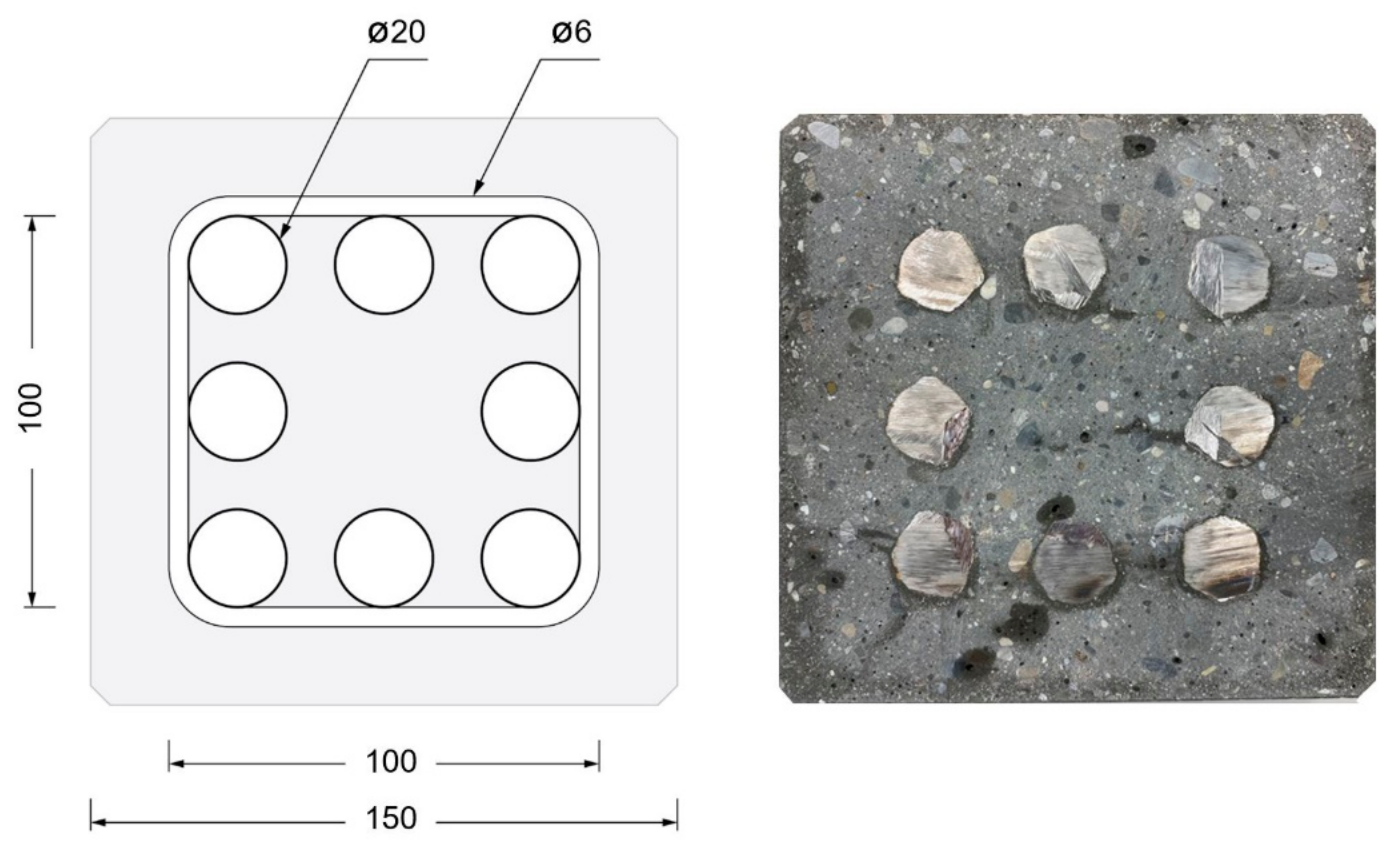
| Rebars | 8 × 20 mm | 8 × 20 mm | 8 × 20 mm | |
| Filling time | 1–2 min | 20 min | 20 min | 66 min |
| Filling rate | 30 L/min (estimated) | 3 L/min | 3 L/min | Variable 1.5, 2.25, 3.00 L/min |
| Curing temp. | 23 °C | 23 °C | 22 °C | |
| Demolding time | 8 h | 4 h | 3 h | |
| Compressive Strength after 4 h | -- | 16 MPa | 18 MPa | |
| Compressive Strength after 28 d | 90 Mpa | 85 MPa | 88 Mpa | |
| Surface quality | Good | Good | Very good (see Figure 9 Right) |
Publisher’s Note: MDPI stays neutral with regard to jurisdictional claims in published maps and institutional affiliations. |
© 2022 by the authors. Licensee MDPI, Basel, Switzerland. This article is an open access article distributed under the terms and conditions of the Creative Commons Attribution (CC BY) license (https://creativecommons.org/licenses/by/4.0/).
Share and Cite
Lloret-Fritschi, E.; Quadranti, E.; Scotto, F.; Fuhrimann, L.; Demoulin, T.; Mantellato, S.; Unteregger, L.; Burger, J.; Pileggi, R.G.; Gramazio, F.; et al. Additive Digital Casting: From Lab to Industry. Materials 2022, 15, 3468. https://doi.org/10.3390/ma15103468
Lloret-Fritschi E, Quadranti E, Scotto F, Fuhrimann L, Demoulin T, Mantellato S, Unteregger L, Burger J, Pileggi RG, Gramazio F, et al. Additive Digital Casting: From Lab to Industry. Materials. 2022; 15(10):3468. https://doi.org/10.3390/ma15103468
Chicago/Turabian StyleLloret-Fritschi, Ena, Elia Quadranti, Fabio Scotto, Lukas Fuhrimann, Thibault Demoulin, Sara Mantellato, Lukas Unteregger, Joris Burger, Rafael G. Pileggi, Fabio Gramazio, and et al. 2022. "Additive Digital Casting: From Lab to Industry" Materials 15, no. 10: 3468. https://doi.org/10.3390/ma15103468
APA StyleLloret-Fritschi, E., Quadranti, E., Scotto, F., Fuhrimann, L., Demoulin, T., Mantellato, S., Unteregger, L., Burger, J., Pileggi, R. G., Gramazio, F., Kohler, M., & Flatt, R. J. (2022). Additive Digital Casting: From Lab to Industry. Materials, 15(10), 3468. https://doi.org/10.3390/ma15103468