
Microstructure and Mechanical Properties of Friction Stir-Welded Dissimilar Joints of ZK60 and Mg-4.6Al-1.2Sn-0.7Zn Alloys

 , ,
, ,
Abstract
:1. Introduction
2. Materials and Methods
2.1. Base Materials
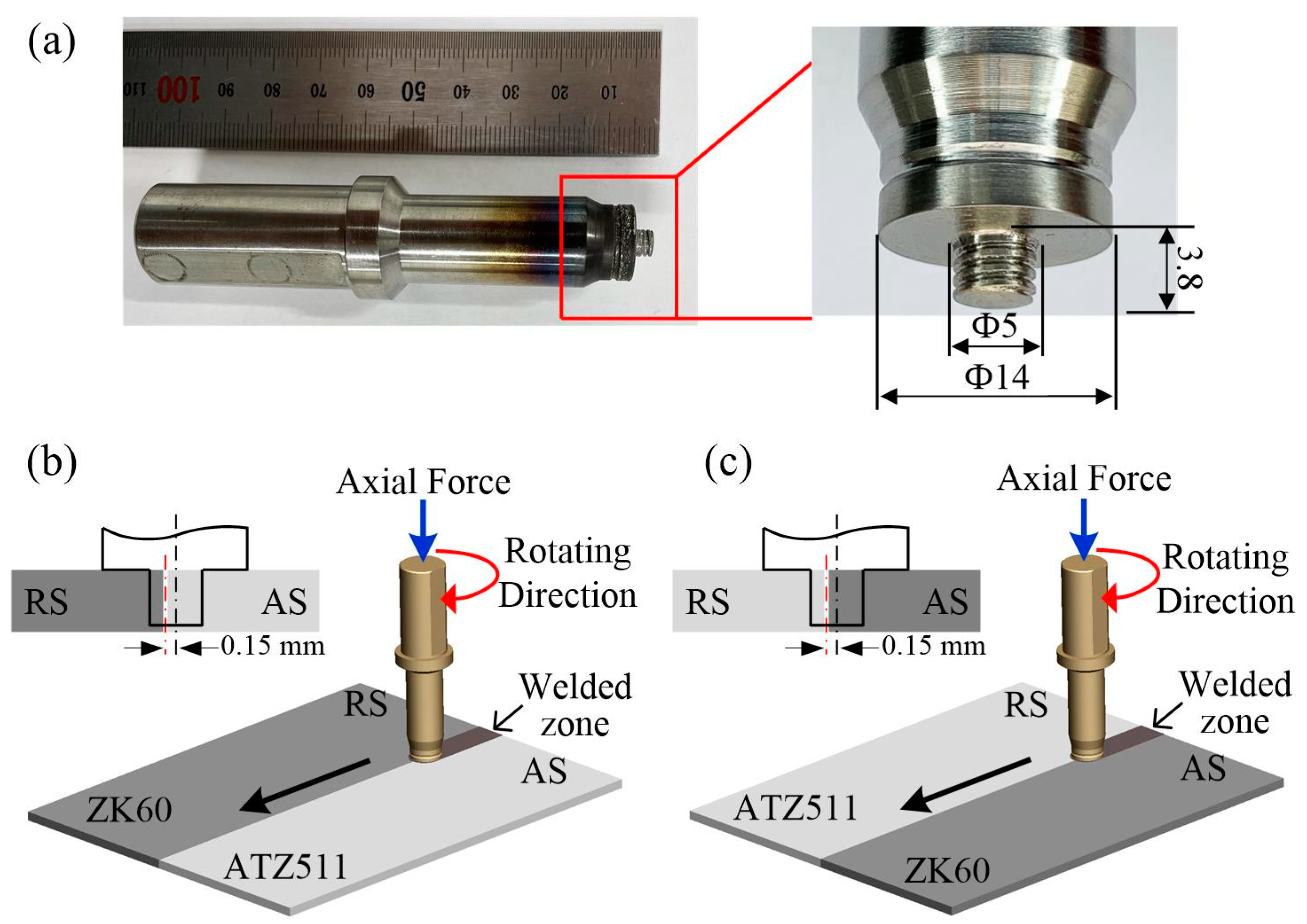
2.2. Welding Procedure
2.3. Microstructure and Mechanical Properties Analysis
3. Results and Discussion
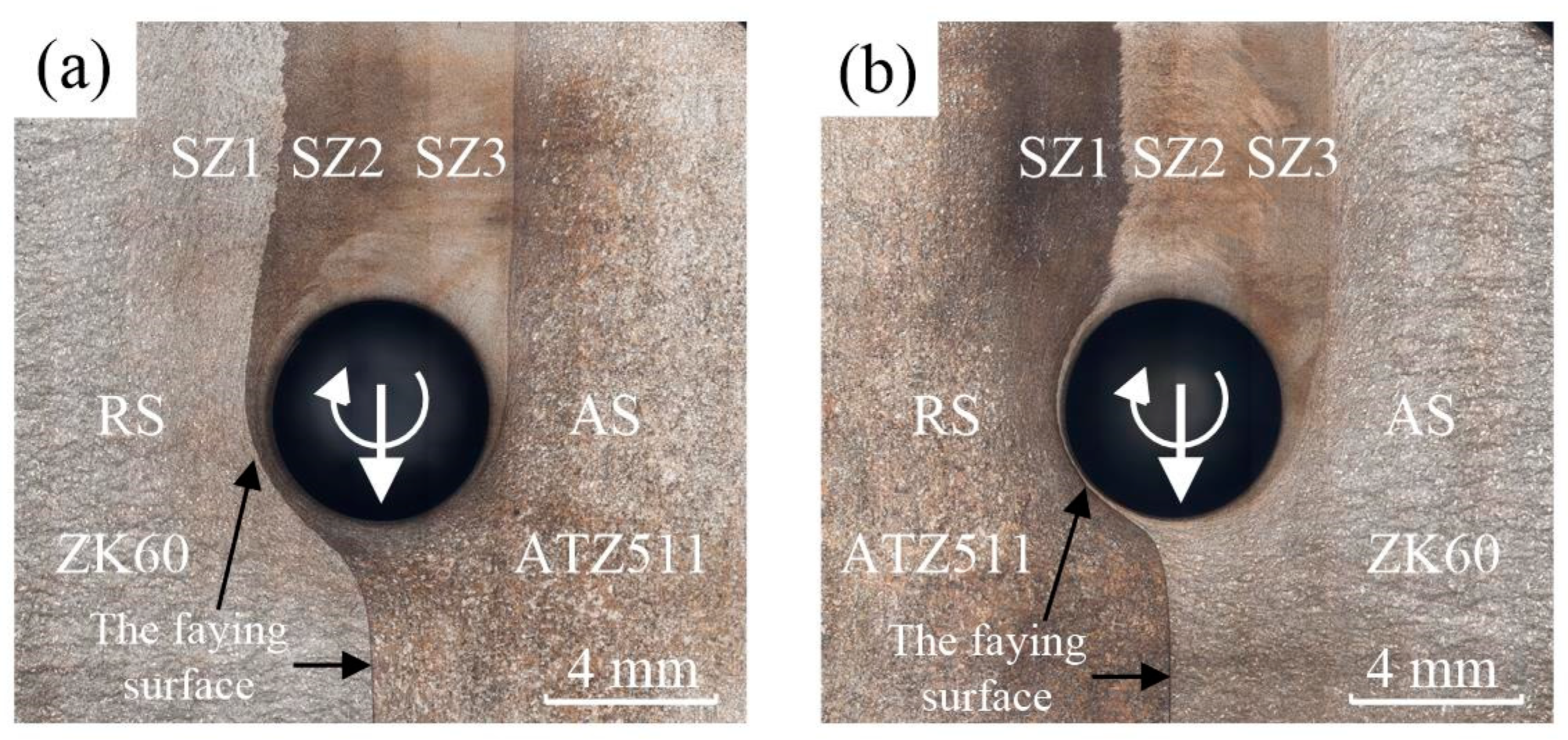
3.1. Macrostructure and Interface
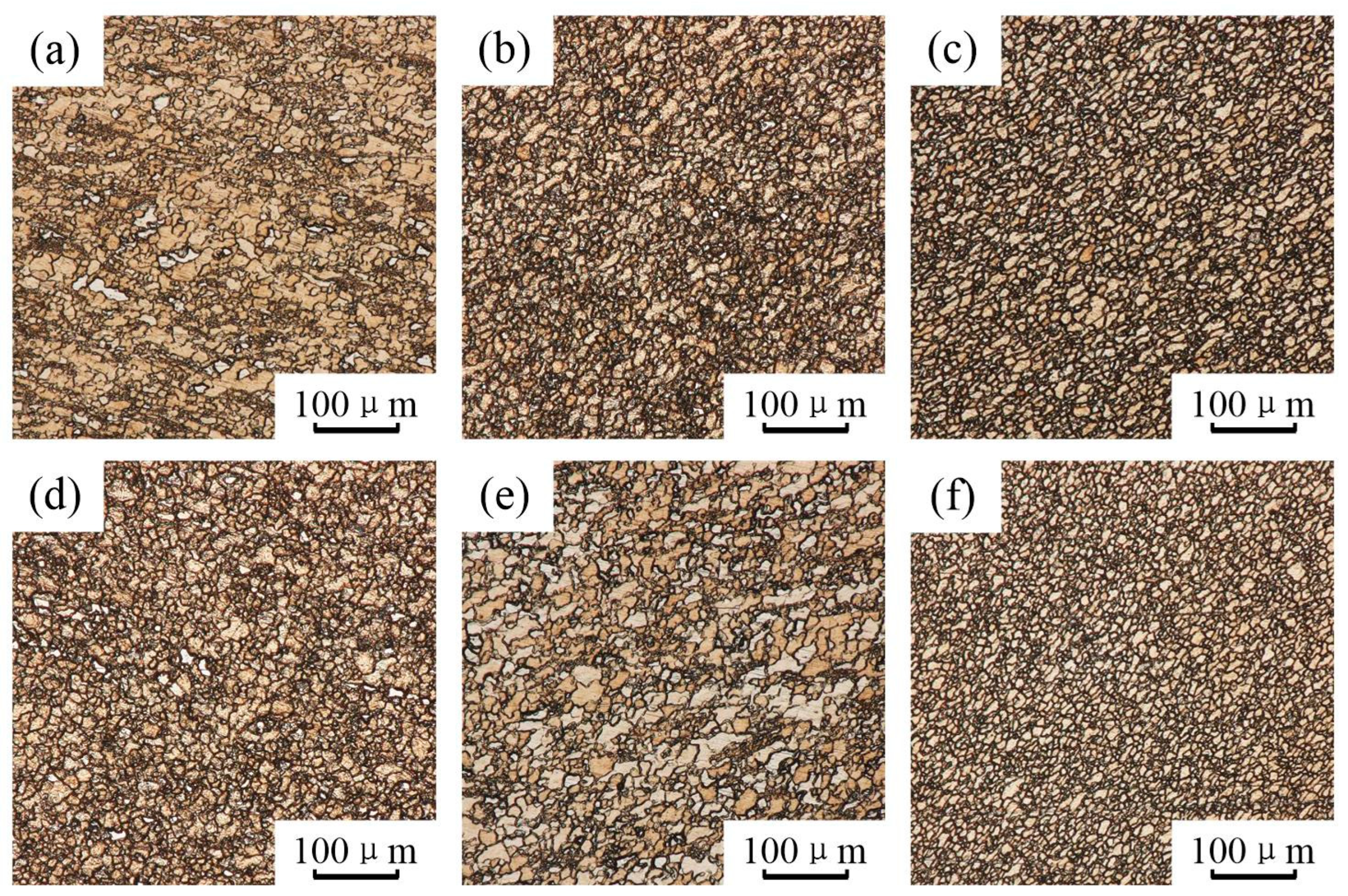
3.2. Microstructure
3.3. Mechanical Properties
3.3.1. Micro Hardness
3.3.2. Tensile Properties
4. Conclusions
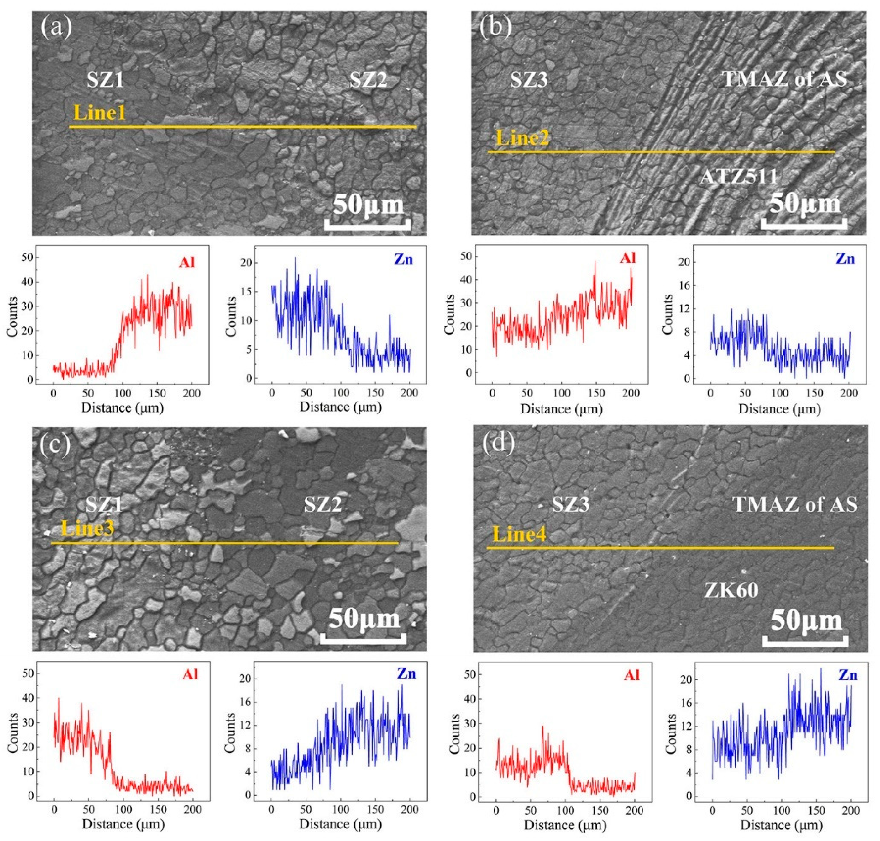
- There are three sub-regions with different compositions in the stirring zone, one region with the ZK60 alloy composition, another region with the ATZ511 alloy composition, and the third region with a mixture of these two alloys. This is attributed to the material flow around the pin and spiral mixing of the two dissimilar alloys caused by the threads on the rotating tool pin.
- The original faying surface of two plates was extruded by the tool shoulder and the tool pin, and finally formed a clear irregular interface within the SZ. There was inter-diffusion of alloying elements on this interface. The interface between the SZ and the TMAZ on the AS was clearly seen.
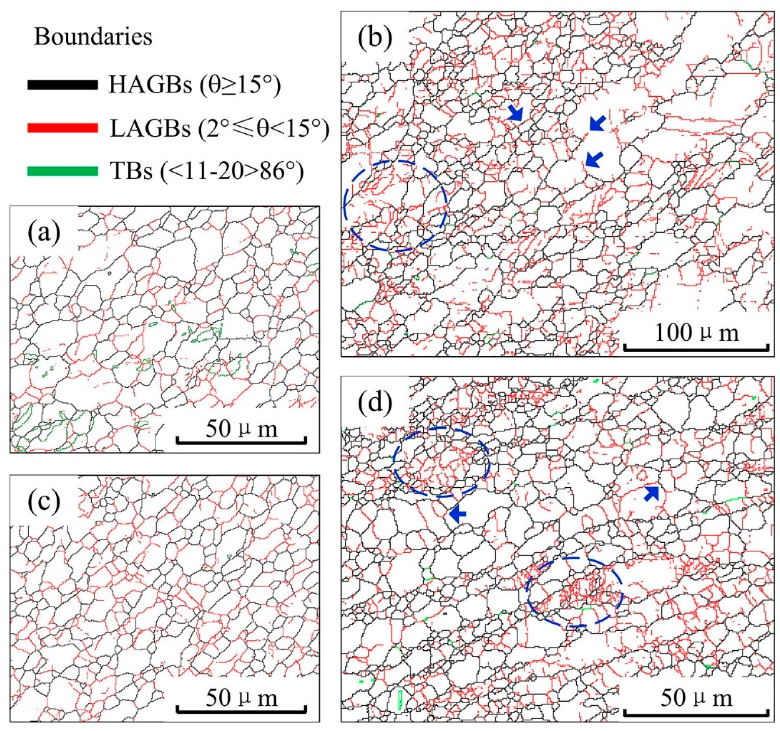
- There are more uniform microstructures in the SZ compared to the BMs, which is attributed to the DRX. The grain size of ZK60 within the SZ increased slightly, while the grain size of ATZ511 within the SZ decreased significantly. This phenomenon is mainly due to the growth of the recrystallized grains. There is no significant difference in grain size within the SZ of joints with two types of arrangement.
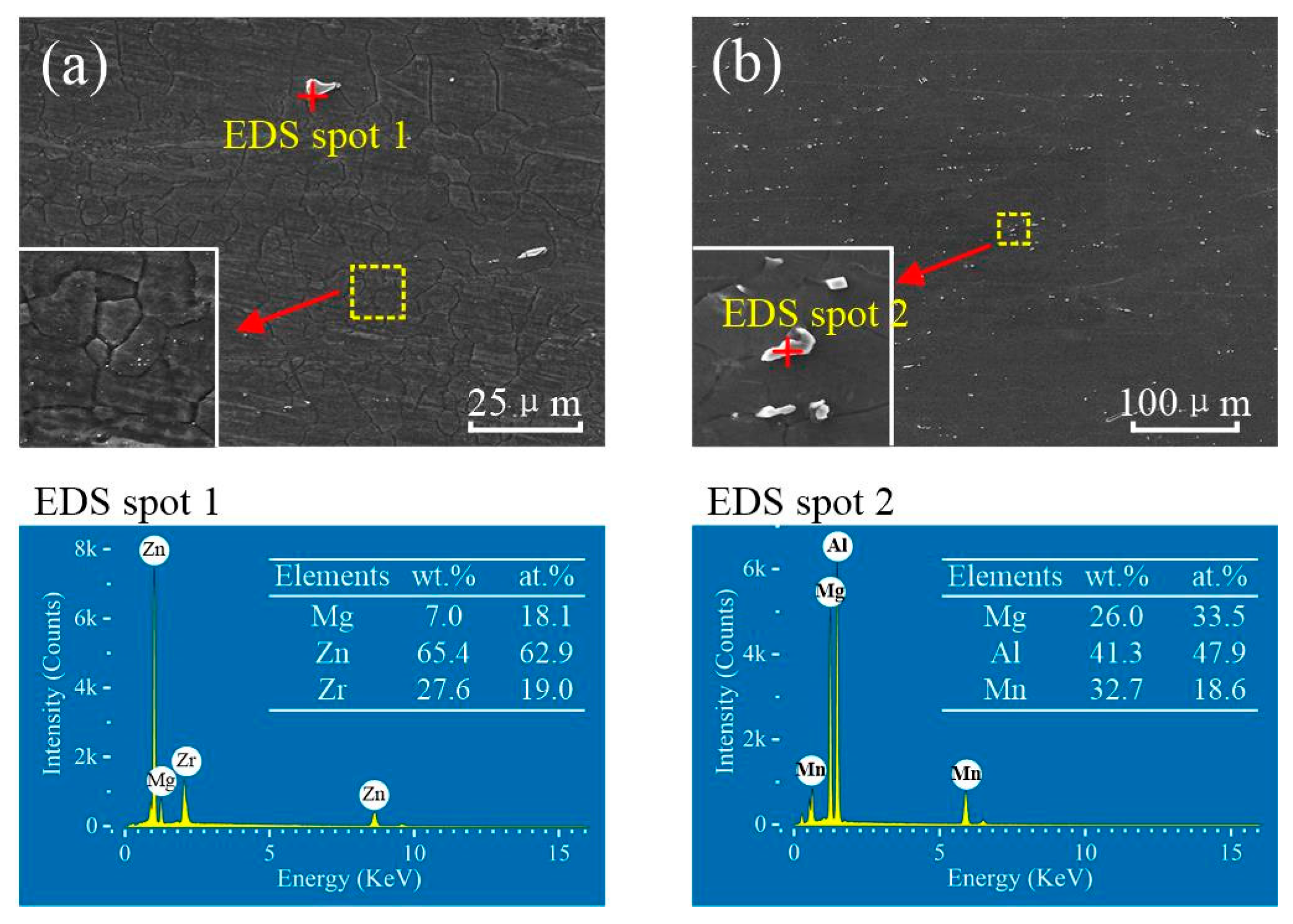
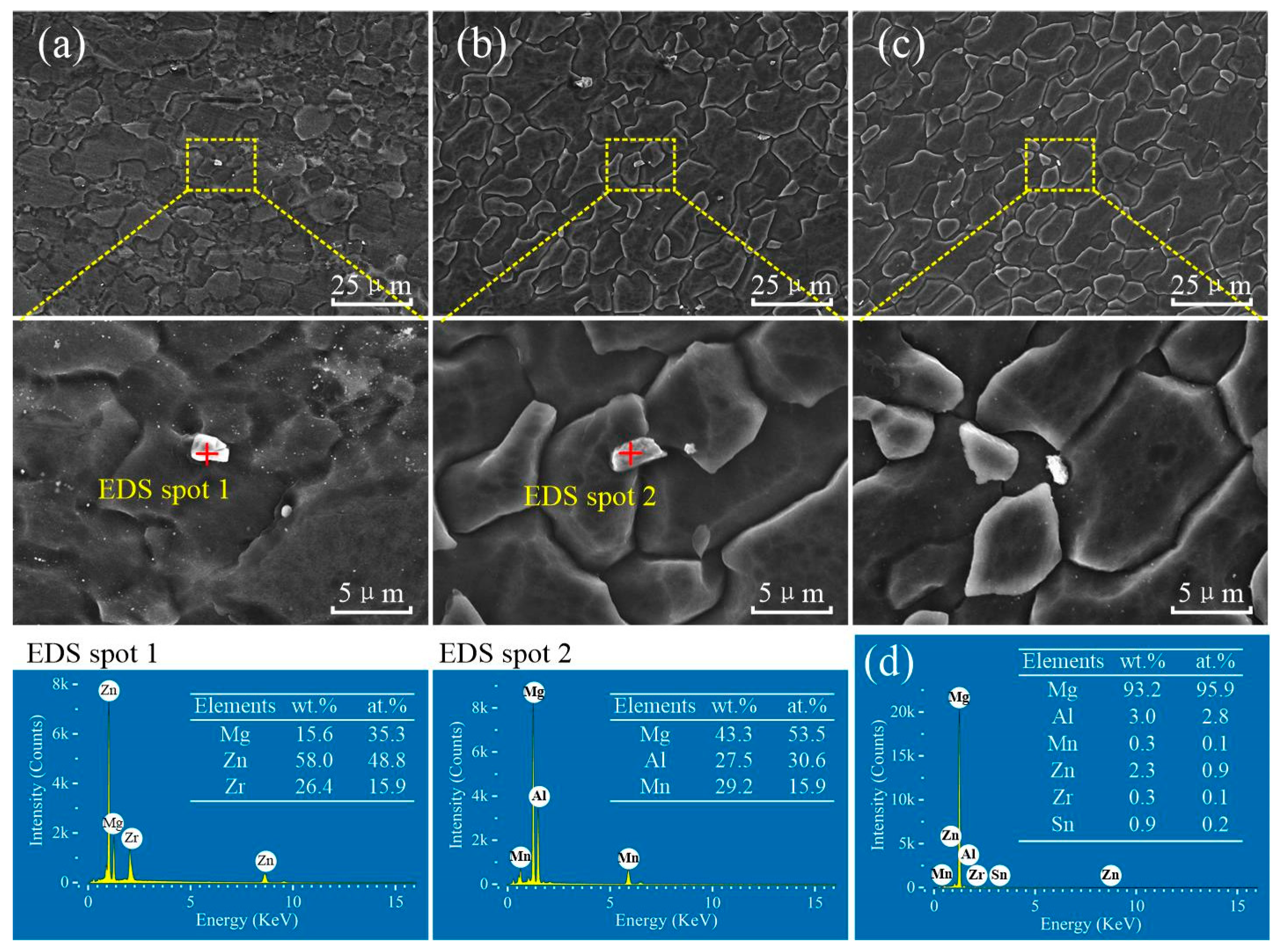
- The fragmentation and dissolution of precipitate particles are gradually significant from the RS to the AS within the SZ, which is mainly attributed to the gradually intense thermal history and plastic deformation.
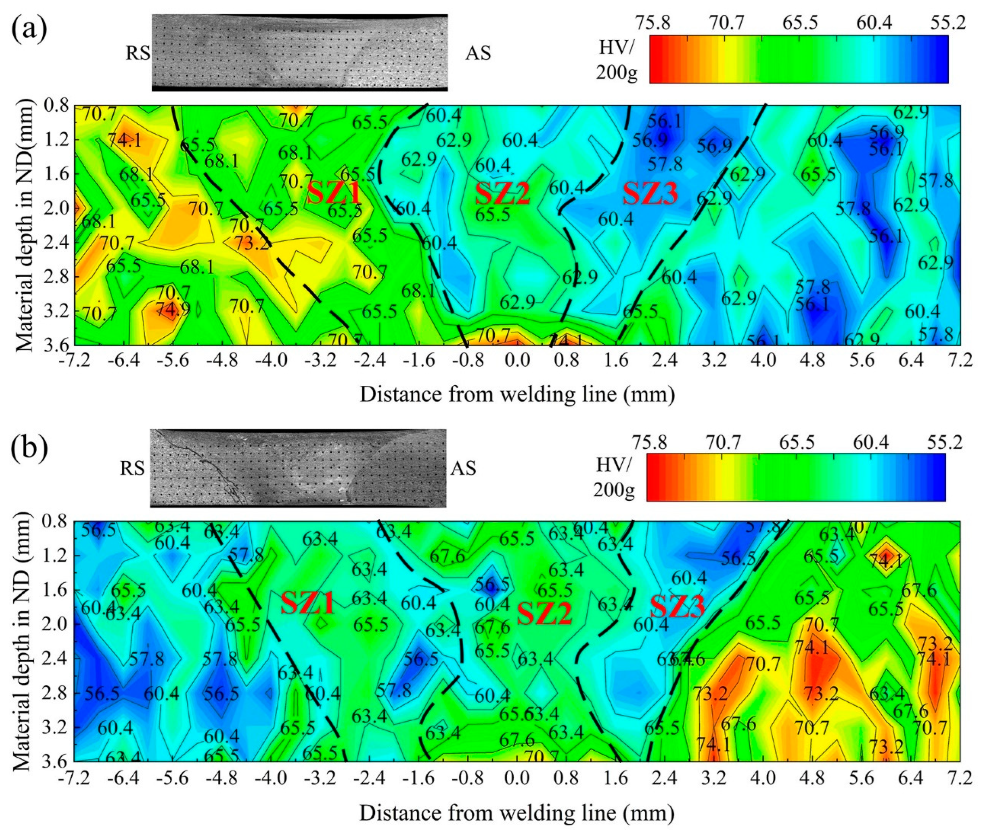
- The distribution of microhardness in the SZ of joints corresponds well to the three subzones with different components. The microhardness value is influenced by both the grains refinement and the precipitates dissolution, where the grain refinement can cause an increase in hardness and the precipitates dissolution can result a decrease in hardness.
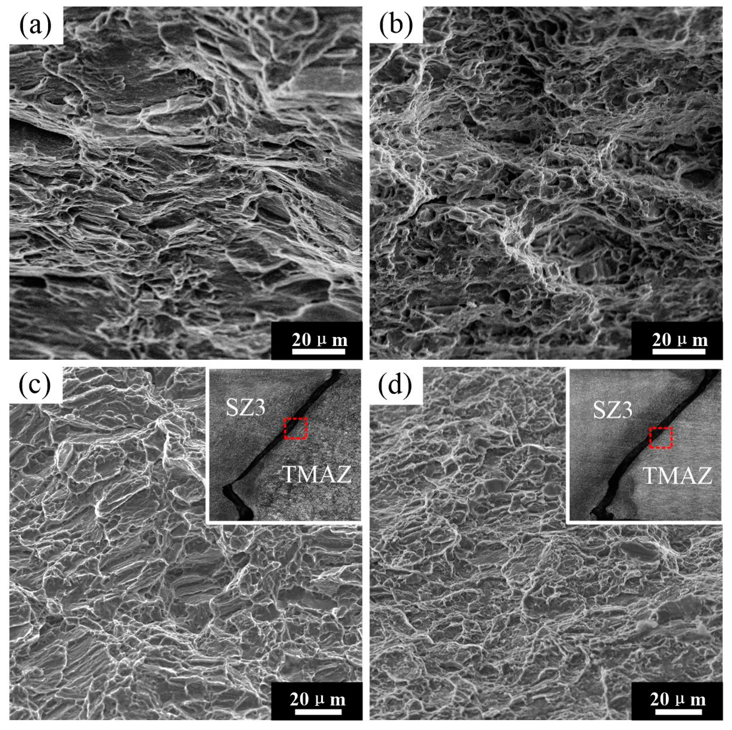
- The UTS of the joint obtained with ZK60 placed on the RS (259 MPa) is slightly better than that of the joint obtained with ZK60 placed on the AS (238 MPa). The tensile fracture of both joints occurred at the boundary between the SZ and the TMAZ on the AS, and shows a quasi-dissociative fracture.
Author Contributions
Funding
Institutional Review Board Statement
Informed Consent Statement
Data Availability Statement
Conflicts of Interest
References
- Wang, W.; Han, P.; Peng, P.; Zhang, T.; Liu, Q.; Yuan, S.N.; Huang, L.Y.; Yu, H.L.; Qiao, K.; Wang, K.S. Friction Stir Processing of Magnesium Alloys: A Review. Acta Metall. Sin.-Engl. 2020, 33, 43–57. [Google Scholar] [CrossRef] [Green Version]
- Singh, K.; Singh, G.; Singh, H. Review on friction stir welding of magnesium alloys. J. Magnes. Alloys 2018, 6, 399–416. [Google Scholar] [CrossRef]
- Singh, U.K.; Dubey, A.K. Study of Weld Characteristics in Friction Stir Welding of Dissimilar Mg-Al-Zn Magnesium Alloys under Varying Welding Conditions. J. Mater. Eng. Perform. 2021, 30, 7690–7703. [Google Scholar] [CrossRef]
- Yajie, L. A Review: Effect of Friction Stir Welding on Microstructure and Mechanical Properties of Magnesium Alloys. Metals 2017, 7, 524. [Google Scholar] [CrossRef] [Green Version]
- Qin, B.; Yin, F.-C.; Zeng, C.-Z.; Xie, J.-C.; Shen, J. Microstructure and mechanical properties of TIG/A-TIG welded AZ61/ZK60 magnesium alloy joints. Trans. Nonferrous Metals Soc. China 2019, 29, 1864–1872. [Google Scholar] [CrossRef]
- Luo, C.; Li, X.; Song, D.; Zhou, N.; Li, Y.; Qi, W. Microstructure evolution and mechanical properties of friction stir welded dissimilar joints of Mg–Zn–Gd and Mg–Al–Zn alloys. Mater. Sci. Eng. A 2016, 664, 103–113. [Google Scholar] [CrossRef]
- Mishra, R.S.; Ma, Z.Y. Friction stir welding and processing. Mater. Sci. Eng. R Rep. 2005, 50, 1–78. [Google Scholar] [CrossRef]
- Mabuwa, S.; Msomi, V. Review on Friction Stir Processed TIG and Friction Stir Welded Dissimilar Alloy Joints. Metals 2020, 10, 142. [Google Scholar] [CrossRef] [Green Version]
- Su, H.; Wang, T.; Wu, C.S. Formation of the periodic material flow behaviour in friction stir welding. Sci. Technol. Weld. Join. 2021, 26, 286–293. [Google Scholar] [CrossRef]
- Ratna Sunil, B.; Pradeep Kumar Reddy, G.; Mounika, A.S.N.; Navya Sree, P.; Rama Pinneswari, P.; Ambica, I.; Ajay Babu, R.; Amarnadh, P. Joining of AZ31 and AZ91 Mg alloys by friction stir welding. J. Magnes. Alloys 2015, 3, 330–334. [Google Scholar] [CrossRef] [Green Version]
- Mironov, S.; Onuma, T.; Sato, Y.S.; Kokawa, H. Microstructure evolution during friction-stir welding of AZ31 magnesium alloy. Acta Mater. 2015, 100, 301–312. [Google Scholar] [CrossRef]
- Suhuddin, U.F.H.R.; Mironov, S.; Sato, Y.S.; Kokawa, H.; Lee, C.W. Grain structure evolution during friction-stir welding of AZ31 magnesium alloy. Acta Mater. 2009, 57, 5406–5418. [Google Scholar] [CrossRef]
- Li, G.; Zhou, L.; Zhang, J.; Luo, S.; Guo, N. Macrostructure, microstructure and mechanical properties of bobbin tool friction stir welded ZK60 Mg alloy joints. J. Mater. Res. Technol. 2020, 9, 9348–9361. [Google Scholar] [CrossRef]
- Xie, G.M.; Ma, Z.Y.; Geng, L. Effect of microstructural evolution on mechanical properties of friction stir welded ZK60 alloy. Mater. Sci. Eng. A 2008, 486, 49–55. [Google Scholar] [CrossRef]
- Liu, D.; Xin, R.; Zhao, L.; Hu, Y.; Zhang, J. Evaluation of corrosion and wear resistance of friction stir welded ZK60 alloy. Sci. Technol. Weld. Join. 2017, 22, 601–609. [Google Scholar] [CrossRef]
- Liu, W.M.; Yan, Y.F.; Ni, R.Y.; Sun, T.; Wu, S.Y.; Shen, Y.F. Influence of preheating temperature on the friction stir welded ME20M magnesium alloy. Sci. Technol. Weld. Join. 2021, 26, 136–143. [Google Scholar] [CrossRef]
- Yang, J.; Xiao, B.L.; Wang, D.; Ma, Z.Y. Effects of heat input on tensile properties and fracture behavior of friction stir welded Mg–3Al–1Zn alloy. Mater. Sci. Eng. A 2010, 527, 708–714. [Google Scholar] [CrossRef]
- Pan, F.; Xu, A.; Ye, J.; Tang, A.; Jiang, X.; Ran, Y.; Du, W. Effects of rotation rate on microstructure and mechanical properties of friction stir-welded Mg-5Al-1Sn magnesium alloy. Int. J. Adv. Manuf. Technol. 2016, 91, 389–397. [Google Scholar] [CrossRef]
- Xin, R.L.; Liu, D.J.; Li, B.; Sun, L.Y.; Zhou, Z.; Liu, Q. Mechanisms of fracture and inhomogeneous deformation on transverse tensile test of friction-stir-processed AZ31 Mg alloy. Mater. Sci. Eng. A-Struct. Mater. Prop. Microstruct. Process. 2013, 565, 333–341. [Google Scholar] [CrossRef]
- Yu, Z.; Sheng, G.; Li, T. Effect of microstructure and microtexture on mechanical properties and fracture behaviour of friction stir-welded AZ31/AZ61 joint. Mater. Res. Express 2018, 5, 125801. [Google Scholar] [CrossRef]
- Liu, D.; Xin, R.; Zheng, X.; Zhou, Z.; Liu, Q. Microstructure and mechanical properties of friction stir welded dissimilar Mg alloys of ZK60–AZ31. Mater. Sci. Eng. A 2013, 561, 419–426. [Google Scholar] [CrossRef]
- Liu, D.; Nishio, H.; Nakata, K. Anisotropic property of material arrangement in friction stir welding of dissimilar Mg alloys. Mater. Des. 2011, 32, 4818–4824. [Google Scholar] [CrossRef]
- Zhang, J.; Huang, G.; Liu, S.; Xie, Y.; Wang, G.; Jiang, B.; Tang, A.; Pan, F. Microstructure evolution and mechanical properties of friction stir welded dissimilar joints of as-extruded AM60 and AZ31 alloys. Mater. Sci. Eng. A 2019, 759, 479–489. [Google Scholar] [CrossRef]
- Pan, F.; Xu, A.; Deng, D.; Ye, J.; Jiang, X.; Tang, A.; Ran, Y. Effects of friction stir welding on microstructure and mechanical properties of magnesium alloy Mg-5Al-3Sn. Mater. Des. 2016, 110, 266–274. [Google Scholar] [CrossRef]
- Reynolds, A.P. Visualisation of material flow in autogenous friction stir welds. Sci. Technol. Weld. Join. 2000, 5, 120–124. [Google Scholar] [CrossRef]
- Steuwer, A.; Dumont, M.; Altenkirch, J.; Birosca, S.; Deschamps, A.; Prangnell, P.B.; Withers, P.J. A combined approach to microstructure mapping of an Al-Li AA2199 friction stir weld. Acta Mater. 2011, 59, 3002–3011. [Google Scholar] [CrossRef]
- Liu, D.J.; Tang, Y.C.; Shen, M.X.; Hu, Y.; Zhao, L.Z. Analysis of Weak Zones in Friction Stir Welded Magnesium Alloys from the Viewpoint of Local Texture: A Short Review. Metals 2018, 8, 970. [Google Scholar] [CrossRef] [Green Version]
- Li, G.H.; Zhou, L.; Zhang, H.F.; Guo, G.Z.; Luo, S.F.; Guo, N. Evolution of grain structure, texture and mechanical properties of a Mg–Zn–Zr alloy in bobbin friction stir welding. Mater. Sci. Eng. A 2021, 799. [Google Scholar] [CrossRef]
- Wang, W.; Hu, Y.; Zhang, M.; Zhao, H. Microstructure and mechanical properties of dissimilar friction stir welds in austenitic-duplex stainless steels. Mater. Sci. Eng. A 2020, 787. [Google Scholar] [CrossRef]
- Li, G.; Zhou, L.; Luo, S.; Dong, F.; Guo, N. Microstructure and mechanical properties of bobbin tool friction stir welded ZK60 magnesium alloy. Mater. Sci. Eng. A 2020, 776. [Google Scholar] [CrossRef]
- Xie, G.M.; Ma, Z.Y.; Geng, L.; Chen, R.S. Microstructural evolution and mechanical properties of friction stir welded Mg-Zn-Y-Zr alloy. Mater. Sci. Eng. A-Struct. Mater. Prop. Microstruct. Process. 2007, 471, 63–68. [Google Scholar] [CrossRef]
- Mironov, S.; Motohashi, Y.; Kaibyshev, R. Grain Growth Behaviors in a Friction-Stir-Welded ZK60 Magnesium Alloy. Mater. Trans. 2007, 48, 1387–1395. [Google Scholar] [CrossRef] [Green Version]
- Mosayebi, M.; Zarei-Hanzaki, A.; Abedi, H.R.; Barabi, A.; Jalali, M.S.; Ghaderi, A.; Barnett, M. The correlation between the recrystallization texture and subsequent isothermal grain growth in a friction stir processed rare earth containing magnesium alloy. Mater. Charact. 2020, 163. [Google Scholar] [CrossRef]
- Heidarzadeh, A.; Mironov, S.; Kaibyshev, R.; Çam, G.; Simar, A.; Gerlich, A.; Khodabakhshi, F.; Mostafaei, A.; Field, D.P.; Robson, J.D.; et al. Friction stir welding/processing of metals and alloys: A comprehensive review on microstructural evolution. Prog. Mater. Sci. 2021, 117. [Google Scholar] [CrossRef]
- Chang, C.I.; Lee, C.J.; Huang, J.C. Relationship between grain size and Zener-Holloman parameter during friction stir processing in AZ31 Mg alloys. Scr. Mater. 2004, 51, 509–514. [Google Scholar] [CrossRef]
- Orlov, D.; Raab, G.; Lamark, T.T.; Popov, M.; Estrin, Y. Improvement of mechanical properties of magnesium alloy ZK60 by integrated extrusion and equal channel angular pressing. Acta Mater. 2011, 59, 375–385. [Google Scholar] [CrossRef]
- Zhang, D.; Suzuki, M.; Maruyama, K. Microstructural evolution of a heat-resistant magnesium alloy due to friction stir welding. Scr. Mater. 2005, 52, 899–903. [Google Scholar] [CrossRef]


| Materials | Sn | Zr | Al | Zn | Mn | Si | Fe | Ni | Mg |
|---|---|---|---|---|---|---|---|---|---|
| ZK60 | - | 0.633 | 0.012 | 5.283 | 0.013 | 0.008 | 0.0001 | 0.0001 | Bal. |
| ATZ511 | 1.154 | - | 4.576 | 0.683 | 0.298 | 0.020 | 0.002 | 0.002 | Bal. |
| Materials | YSσ0.2/MPa | UTS/MPa | El/% | Hardness/HV |
|---|---|---|---|---|
| ZK60 | 174.5 | 291.8 | 22.3 | 70.5 |
| ATZ511 | 169.5 | 272.1 | 17.4 | 59.2 |
Publisher’s Note: MDPI stays neutral with regard to jurisdictional claims in published maps and institutional affiliations. |
© 2021 by the authors. Licensee MDPI, Basel, Switzerland. This article is an open access article distributed under the terms and conditions of the Creative Commons Attribution (CC BY) license (https://creativecommons.org/licenses/by/4.0/).
Share and Cite
Xie, L.; Zhu, X.; Fan, Y.; Sun, W.; Wang, P.; Jiang, C.; Xiao, X.; Yang, S.; Song, Y. Microstructure and Mechanical Properties of Friction Stir-Welded Dissimilar Joints of ZK60 and Mg-4.6Al-1.2Sn-0.7Zn Alloys. Materials 2022, 15, 23. https://doi.org/10.3390/ma15010023
Xie L, Zhu X, Fan Y, Sun W, Wang P, Jiang C, Xiao X, Yang S, Song Y. Microstructure and Mechanical Properties of Friction Stir-Welded Dissimilar Joints of ZK60 and Mg-4.6Al-1.2Sn-0.7Zn Alloys. Materials. 2022; 15(1):23. https://doi.org/10.3390/ma15010023
Chicago/Turabian StyleXie, Liangwen, Xianyong Zhu, Yuexiang Fan, Weijia Sun, Peng Wang, Cheng Jiang, Xiong Xiao, Song Yang, and Yulai Song. 2022. "Microstructure and Mechanical Properties of Friction Stir-Welded Dissimilar Joints of ZK60 and Mg-4.6Al-1.2Sn-0.7Zn Alloys" Materials 15, no. 1: 23. https://doi.org/10.3390/ma15010023
APA StyleXie, L., Zhu, X., Fan, Y., Sun, W., Wang, P., Jiang, C., Xiao, X., Yang, S., & Song, Y. (2022). Microstructure and Mechanical Properties of Friction Stir-Welded Dissimilar Joints of ZK60 and Mg-4.6Al-1.2Sn-0.7Zn Alloys. Materials, 15(1), 23. https://doi.org/10.3390/ma15010023