Article

Confinement Effect and Efficiency of Concentrically Loaded RACFCST Stub Columns

1
School of Civil Engineering, Central South University, Changsha 410075, China
2
Engineering Technology Research Center for Prefabricated Construction Industrialization of Hunan Province, Changsha 410075, China
*
Author to whom correspondence should be addressed.
Materials 2022, 15(1), 154; https://doi.org/10.3390/ma15010154
Submission received: 3 November 2021 / Revised: 9 December 2021 / Accepted: 22 December 2021 / Published: 26 December 2021
(This article belongs to the Special Issue Confined Concrete and Its Application in Structural Engineering)

Abstract

:
Recycled aggregate concrete-filled steel tubular (RACFST) columns are widely recognized as efficient structural members that can reduce the environmental impact of the building industry and improve the mechanical behavior of recycled aggregate concrete (RAC). The objective of this study is to investigate the behavior of recycled aggregate concrete-filled circular steel tubular (RACFCST) stub columns subjected to the axial loading. Three-dimensional finite element (FE) models were established using a triaxial plastic-damage constitutive model of RAC considering the replacement ratio of recycled aggregates. The FE analytical results revealed that the decreased ultimate bearing capacity of RACFCST stub columns compared with conventional concrete infilled steel tubular (CFST) columns was mainly due to the weakened confinement effect and efficiency. This trend will become more apparent with the larger replacement ratio of recycled aggregates. A practical design formula of the ultimate bearing capacity of RACFCST stub columns subjected to axial load was proposed on the basis of the reasonably simplified cross-sectional stress nephogram at the ultimate state. The derivation process incorporated the equilibrium condition and the superposition theory. The proposed equation was evaluated by comparing its accuracy and accessibility to some well-known design formulae proposed by other researchers and some widely used design codes.

1. Introduction

The past several decades have witnessed the rapid progress of engineering construction technology and worldwide expedite urbanization, which leads to a continuous updating of design codes to meet the changing requirements of society. Therefore, the Construction & Demolition (C&D) waste is becoming an inevitable problem due to the upgrading of existing engineering structures. As the most commonly used engineering materials by far, concrete has the merits of low price and high compressive strength. According to available survey studies, around 20 billion metric tons concrete were consumed in 2009 [1], and this number exceeded 26 billion metric tons by 2012 [2]. Researchers predicted that the worldwide demand of aggregates will be doubled in the next 20 years [3]. Therefore, social concerns were raised about environmental issues such as carbon dioxide emission, waste of fresh water resources, and energy consumption. Thus, the concrete industry has been seeking a sustainable way to minimize the environmental impact. The recycled aggregate concrete (RAC), as a new type of green building material that emerged in past two decades, can reasonably dispose of and effectively utilize demolished concrete. Hence, RAC is beneficial in terms of saving natural resources and environmental preservation. The waste concrete demolished from existing engineering structures is recycled and crushed as coarse aggregate to produce new concrete. This recycled material has been widely recognized as an attractive and promising alternative to conventional structural concrete among the scientific community.
However, compared with structural concrete utilizing natural aggregates, RAC has some drawbacks verified by experimental studies such as the low strength and elastic modulus, high shrinkage and creep, inferior durability, and large scatter of its tested mechanical properties [4,5,6,7,8]. Those defects stem from the high porosity, the residual adherent mortar, and different sources of waste concrete, which hindered their application in engineering practice. Consequently, the usage of RAC in practical construction usually requires some enhancement treatments regarding the microstructure of recycled aggregates including the heat treatment [9], ultrasonic cleaning [10], carbon dioxide injection [11], etc. [12,13,14]. On the other hand, RAC in some forms of composite structures shows more reliable and uniform mechanical properties and is supposed to overcome the aforementioned application barriers.
One of the most promising structural members in its form that can provide sufficient confinements on concrete and reduce their shrinkage and creep is the concrete-filled steel tubular (CFST) columns [15]. Correspondingly, the recycled aggregate concrete-filled steel tabular (RACFST) columns are a convenient way that can suppress the defects of RAC and improve their mechanical performance. Experimental and numerical studies have already been conducted on the RACFST stub columns with circular and square cross-sections [15,16,17,18,19,20,21,22,23,24]. It can be summarized here that under the axial compression, the structural performance of RACFST stub columns is similar to CFST stub columns in their ultimate bearing capacity and failure modes. Meanwhile, Zhang et al. [20] studied the mechanical performance of RACFST slender columns with circular and square cross-sections under eccentric loading, and they found that the replacement ratio of recycled aggregates has less of an effect on the ultimate bearing capacity compared with the eccentricity and slenderness ratio. Chen et al. [21] used the finite element model (FEM) to investigate the behavior of the RACFST stub columns under axial loading. The validation of the established FE model was verified against the test results, and a parametric study was conducted to propose a design formula for calculating the ultimate axial-bearing capacity based on the modification of the code for the design of a steel–concrete composite structure (DL/T 5085-1999) [22]. Some scholars have found that the existing design codes cannot precisely predict the ultimate axial-bearing capacity of RACFST stub columns and therefore proposed virous formulae [16,21,23,24]. For instance, Wang et al. [15] carried out an experimental study of thirty-nine stub columns to investigate their compressive behavior with normal-strength RACFST stub columns. The results showed that the source and the replacement ratio of recycled aggregates slightly affect the static responses and collapse process of the RACFST specimens. An experimental study that contains 32 RACFST specimens was reported by Lyu [25]. The confinement factor and the material strength were found to be the most influential to the bearing capacity of the columns, while the replacement ratio of coarse aggregate considerably affects the strength index of the RAC. The applicability of using the current design provisions of CFST stub columns to calculate the RACFST columns was evaluated using the experiment data. It was found that the well-known design codes of CFST stub columns more or less underestimate the sectional capacity of RACFST stub columns. It should be noticed here that some of newly proposed formulae are too cumbersome to use in design and lack clear physical meanings despite their higher accuracy.
To sum up, past studies partially addressed the understanding of mechanical behavior of RACFST columns under axial loading and verified its prospect in engineering application. However, more in-depth investigations are required to clearly explain the structural behavior such as the confinement effect and efficiency and their relations with the design parameters. In the meantime, the promotion of RAC usage in engineering practice requires more practical and simple yet accurate design tools. To date, the specific calculation method of the ultimate bearing capacity of RACFST stub columns is still rare, and the current design formulae of CFST stub columns were reported as not appropriate. The differences between the confinement effect of the steel tube and infilled RAC and that of normal concrete counterparts should be noticed, including the discrepancy of stress variation of infilled RAC and normal infilled concrete and the correspond steel tube stress variation.
To this end, on the basis of past research of CFST stub columns under axial loading [26], this study investigated the confinement effect and efficiency of RACFCST stub columns and proposed a practical design formula with concise physical sense for the calculation of their axial-bearing capacity. The main contents of this paper include the following. (1) A full-scale FE model of RACFST stub columns was established by adopting the triaxial plastic damage constitutive model of recycled aggregate concrete considering the replacement ratio of recycled aggregate. (2) Available test results of axially loaded RACFCST stub columns were collected. Non-linear FE analysis was conducted to reproduce the collected test results. (3) A parametric study was performed on the basis of the validated FE model to investigate the different confinement effect and efficiency between CFCST and RACFCST stub columns. (4) By means of the superposition method and a large number of numerical results, a practical design formula with concise physical sense was derived. (5) The performance of the proposed design formula was compared with the formulae of well-known international codes.

2. Finite Element Modeling of RACFCST Stub Columns

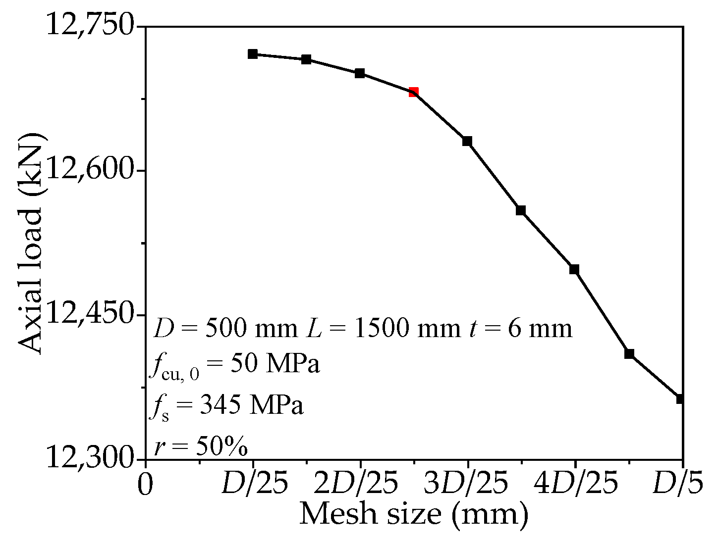
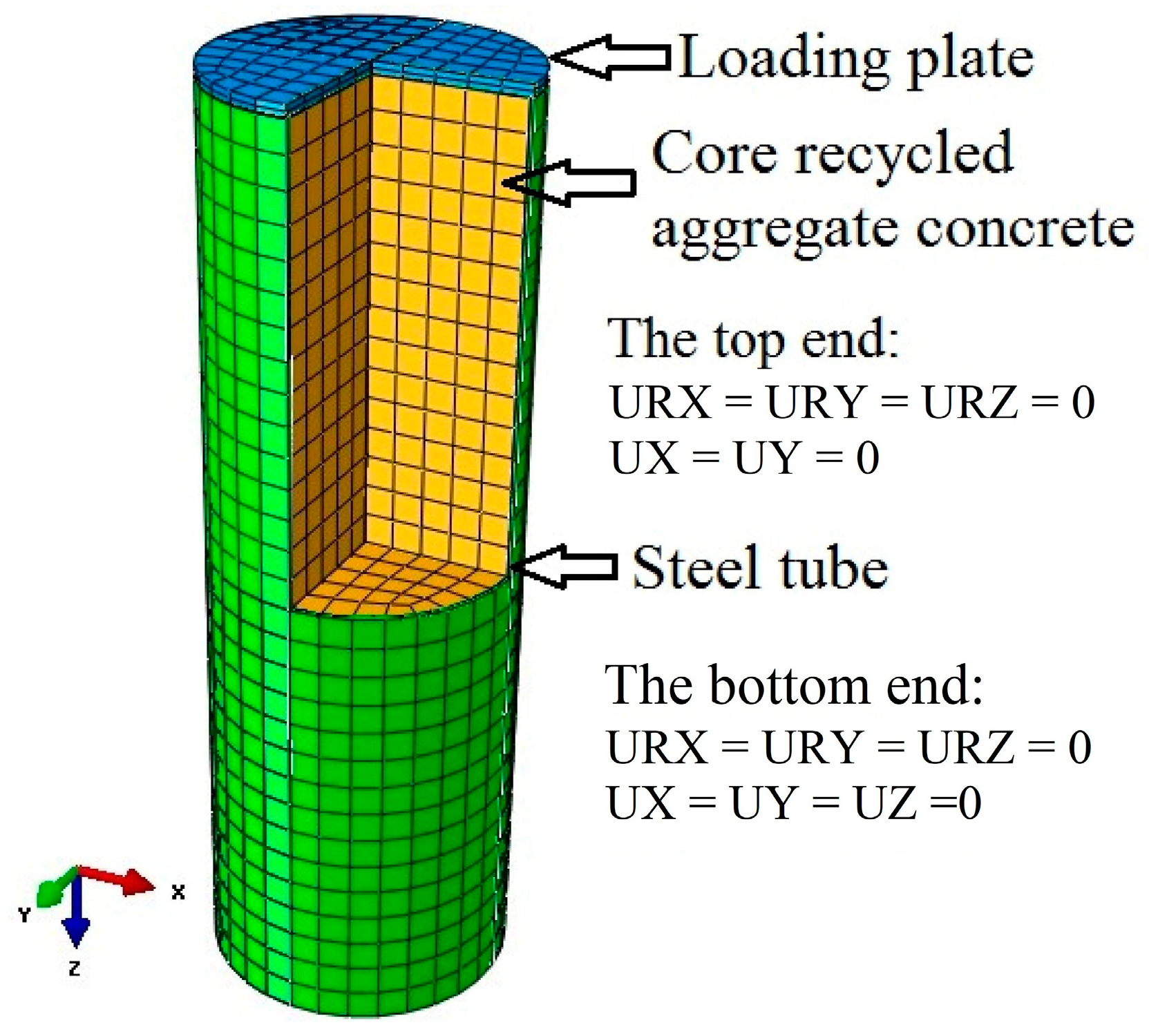
2.1. Modeling Method

ABAQUS is widely regarded as the most powerful finite element software for the analysis of complex solid mechanical structural mechanical systems, especially for the control of very large and complex problems and the simulation of highly non-linear problems.
Non-linear FE models of axially compressed RACFCST stub columns were established making use of the commercially available software ABAQUS version 6.14 [27]. The outer steel tube, infilled RAC, and the loading instrument were modeled by the eight-node reduced integral format 3D solid element (C3D8R) provided by the software element library.
The mesh size will affect the accuracy of the FE model and computation time. Choosing a proper mesh size is important to reasonably replicate the test results. In order to identify the optimal mesh size, a convergence study was performed. The scope of the mesh size is from D/25 to D/5, where D means the outer diameter of RACFCST stub columns. Figure 1 presents the influence of mesh size on the ultimate bearing capacity. The results revealed that the model with D/10 mesh size and those with smaller mesh size predicted similar axial-bearing capacity with the difference being less than 1%. The results predicted by the larger mesh size are sensitive to the change of element size. Therefore, the mesh size is selected as D/10 in the modeling. The mesh generation and boundary conditions of the established FE model are shown in Figure 2.
The interaction between the steel tube and the infilled RAC was conducted in a surface-to-surface contact model. The main surface is the inner surface of steel pipe, and the secondary surface is the outer surface of concrete. The sliding formulation was chosen as “finite sliding”, and the discretization method was chosen as “surface-to-surface”. The contact properties between the steel pipe and infilled RAC were simulated by normal and tangential behavior. In the normal behavior setting, the “Pressure-Overclosure” was set to “hard” contact mode, and the separation after contact was allowed. The penalty function was set as the tangential behavior of the contact attribute, in which the friction coefficient was 0.5 [7]. A tie constraint may couple two separate surfaces so that no relative motion occurs between them. Thus, in order to ensure that the axial load is applied to the whole column section at the same time in the loading process, the “tie” constraint mode provided by ABAQUS was adopted to constrain the loading plate (main surface) and the RACFCST stub column (secondary surface). The loading plate was assumed to be rigid and was simulated by approximate rigid material in which the elastic modulus was taken as 1.0 × 10¹² MPa and the Poisson’s ratio was set as 1.0 × 10⁻⁷.

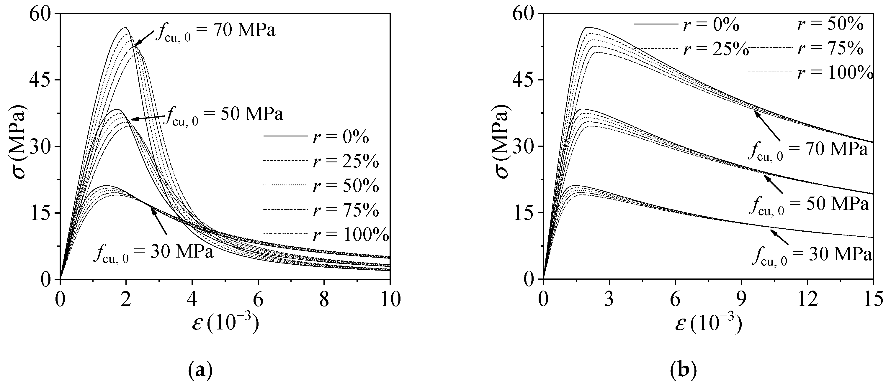
2.2. Constitutive Relation of Infilled Recycled Aggregate Concrete

In this study, the uniaxial full-range stress–strain relation of RAC proposed by Ding et al. [28] was applied to express the compressive behavior of the infilled RAC. This model modified the previous proposed stress–strain relation of conventional concrete [29] and has been verified to be valid in past investigations [30]. The full range stress–strain relation of RAC can be represented by Equation (1).
y = { A 1 ( r ) x + ( B 1 ( r ) 1 ) x 2 1 + ( A 1 ( r ) 2 ) x + B 1 ( r ) x 2 x 1 x α 1 ( r ) ( x 1 ) 2 + x x > 1
A 1 ( r ) = ( 1 0.3 r ) ( 1 + 0.2 r ) ( 1 0.1 r ) × 9.1 f cu 4 / 9 B 1 ( r ) = 5 ( A 1 ( r ) 1 ) 2 / 3 y = σ / f c ( r ) ,   x = ε / ε c ( r ) α 1 ( r ) = 2.5 × 10 5 f cu 3 f c ( r ) = ( 1 0.1 r ) f c , f cu ( r ) = ( 1 0.1 r ) f cu ε c ( r ) = ( 1 + 0.2 r ) ε c , E c ( r ) = ( 1 0.3 r ) E c
where r, A1(r), B1(r), α1(r), fc(r), fc, fcu(r), fcu, εc, εc(r), Ec, and Ec(r) are the parameters to determine the uniaxial behaviors of the RAC; their detailed definition can be found in the reference [29]. The σ and ε are the stress and strain of RAC, respectively.
Combining the σ-ε relation of RAC under uniaxial compression and the strength criterion parameters of concrete under multiaxial stress [29], the triaxial constitutive model of RAC was derived. The plastic damage model in ABAQUS was adopted, and its parameters were defined as shown in Table 1 [26,29].
The diagrams of confined and unconfined plastic-damage model of recycled aggregate concrete are shown in Figure 3.

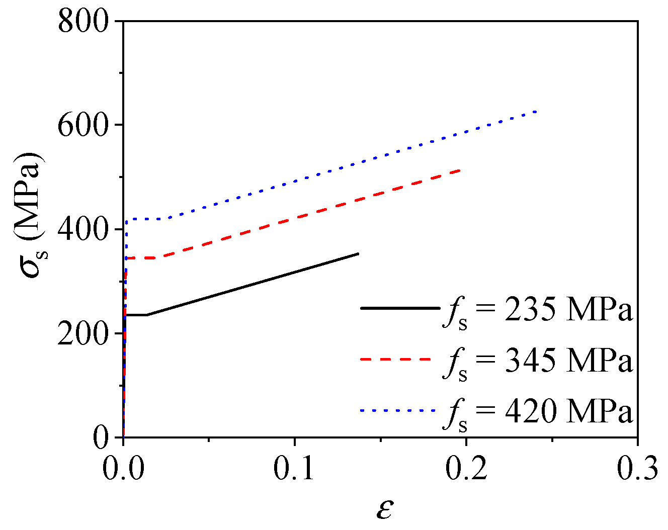
2.3. Constitutive Relation of Steel Tube

The adopted stress–strain model of an outer steel tube is an elasto-plastic model. Meanwhile, this model considers the Von Mises yield criteria, Prandtl–Reuss flow rule, and isotropic strain hardening. The expression is as follows [29]:
σ i = { E s ε i ε i ε y f s ε y < ε i ε s t f s + ζ E s ( ε i ε s t )   ε st < ε i ε u   f u ε i > ε u
where σi is the equivalent stress; fu is the ultimate strength of steel, which is equal to 1.5 times the yield strength fs; the Young’s modulus Es is 2.06 × 10⁵ MPa; εi stands for the equivalent strain of steel; εy means the yield strain; εst means the hardening strain and is equal to 12 times εy; εu is the ultimate strain and is equal to 120 times εy; and ζ is a parameter chosen as 1/216. This steel model has been verified in previous studies of concrete-filled steel tubular columns subjected to axial loading [31,32,33,34], shear [35], torsion [36], and cyclic loading [37]. The stress–strain relations of steel derived by the adopted model with different yield strengths is shown in Figure 4.

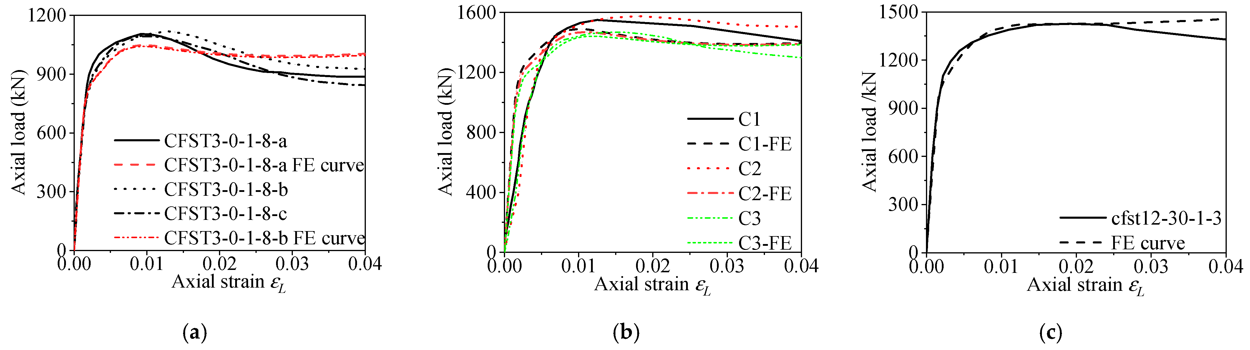
2.4. Model Validation

The validity of the FE models was verified by comparing the existing RACFCST axial compression stub column test data [38,39,40,41,42,43,44,45,46] with the FE calculation results. Since the test method of mechanical properties of concrete and the compressive strength indexes adopted by various scholars are different, the concrete strength conversion formulae (cylinder strength f c to concrete cube strength fcu [47], cube with side length of 100 mm fcu,100 to 150 mm fcu,150 [29]) are shown in Equations (4) and (5). In this study, the unified compressive cubic strength of 150 mm cube was adopted, which is represented by fcur150 in Table 2.
f c = { 0.8 f cu f cu 50 MPa f cu 10 f cu > 50 MPa
f cu , 150 = 1.17   f cu , 100 0.95 0.7
To verify the applicability and accuracy of the established FE model, the calculated ultimate bearing capacity of collected specimens was compared with the test results. The ratios of the test results to FE results (Nu,exp/Nu,FE) are presented in Table 2. According to the normalized comparison, the mean value of the ratios (Nu,exp/Nu,FE) was 0.978, and the variable coefficient is 0.048, which indicates that the ultimate bearing capacity predicted by the established FE model is in good agreement with the experimental results. Meanwhile, Figure 5 compares some typical load–strain curves obtained by FE analysis and the experiment. It can be seen that the ultimate bearing capacity and initial stiffness obtained from FE analysis fit well with the test results. It is worth mentioning that the FE curves before the peak load point match well with the test curves. Due to concrete crushing or local buckling of steel tubes, the test curves are slightly lower than the FE curves at the later loading stage. The comparisons indicate that the FE model is in good agreement with the experimental results, especially in the prediction of ultimate bearing capacity. Hence, the FE models in this paper can be used for the further numerical study of the RACFCST stub columns under axial compression. Additionally, it is worth mentioning that the average axial strains of the specimen C1, C2, and C3 shown in Figure 5b are converted from the full-height compression of the specimens obtained from the displacement gauge, which could result in a smaller elastic stiffness.

3. Investigation of Confinement Effect and Efficiency of RACFCST Stub Columns under Axial Loading

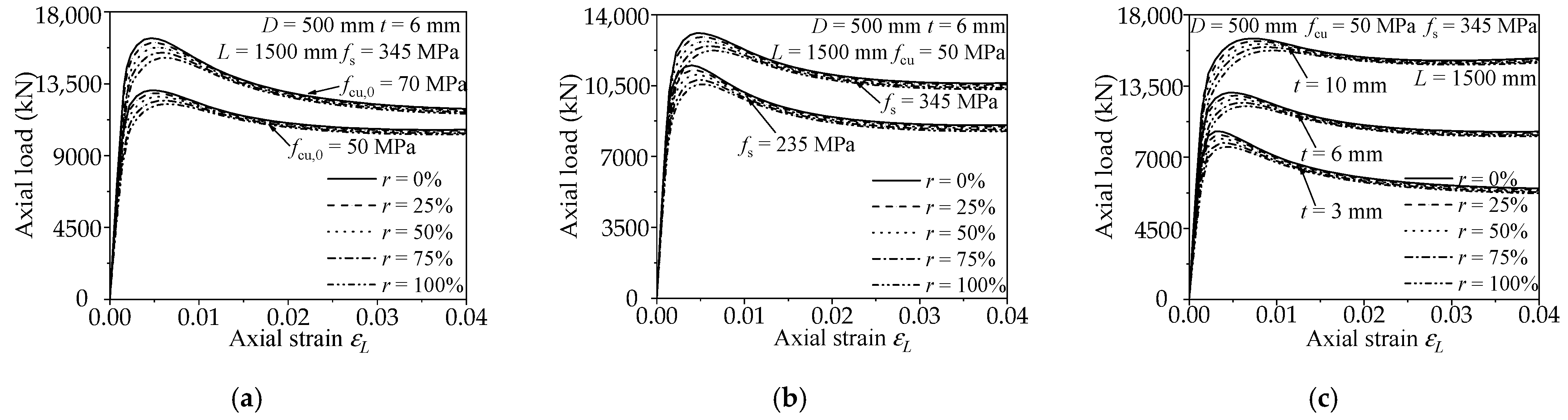
3.1. Parametric Analysis

To investigate the axial loaded behaviors of RACFCST stub columns, a parametric study including 75 full-scale FE models based on the aforementioned validated FE modelling approach is conducted. The following are the main parameters analyzed in this study, including size and strength: the diameter of composite section D = 500 mm; the columns height L = 1500 mm; the tube wall-thickness t = 3 mm, 6 mm, and 10 mm, respectively; the steel ratios ρ range from 2 to 8%; the strength matching of concrete and steel and the replacement rate of recycled aggregate are shown in Table 3. fcu,0 means the plain concrete cubic compressive strength. The influence of fcu,0, fs, ρ, and r on the axial loaded behaviors is presented in Figure 6. It can be found that semblable to the CFCST stub columns, the material strengths, and specimen dimensions have a significant effect on the ultimate bearing capacity of RACFCST stub columns.

3.2. Evaluation Criterion of the Confinement Effect and Efficiency

The confinement effect is the most valued characteristic of CFST columns caused by the interaction between the steel tube and infilled concrete. The confinement effect can be evaluated by the radial stress σr,c of infilled concrete at the ultimate state. In general, the infilled concrete will show better mechanical performance under the stronger confinement effect provided by the outer steel tube. However, the radial stress at the ultimate state cannot reflect the utilization efficiency of the steel tube strength and the variation of composite action during the loading process. Hence, two indexes were investigated in this study to evaluate the appropriateness of different design parameters. The utilization efficiency of steel strength can be evaluated by the radial concrete confinement coefficient (ξr,c = σr,c/(ρfs)). The composite action can be assessed by the occurrence of the intersection point of the axial stress–strain curve and the transverse stress–strain curve of a steel tube. In general, the greater the radial concrete confinement coefficient is, the better the utilization efficiency of the steel tube on the infilled concrete. The composite action can be reflected by the axial and transverse stress–strain curves of the steel, and the intersection of axial and lateral stress–strain curves indicate the best composite action point of the composite structures. The two stress–strain curves intersecting early means the composite action and the confinement efficiency were better [48]. Hence, the aforementioned indexes were utilized herein to assess the confinement effect and efficiency as the design parameters change.

3.2.1. Concrete Strength

The influence on the confinement effect and efficiency of the RACFCST stub columns caused by different concrete strength (fcu) is shown in Figure 7. Figure 7a,b demonstrate that as the loading progress goes on, the radial stress σr,c and the radial concrete confinement coefficient ξr,c of fcu,0 = 70 MPa are slightly lower in the early stage but are greater in the late stage. Meanwhile, the longitudinal and the lateral stress–strain curve of fcu,0 = 70 MPa intersected earlier. It can be concluded that the effect and efficiency of confinement increase with the increase of concrete strength.

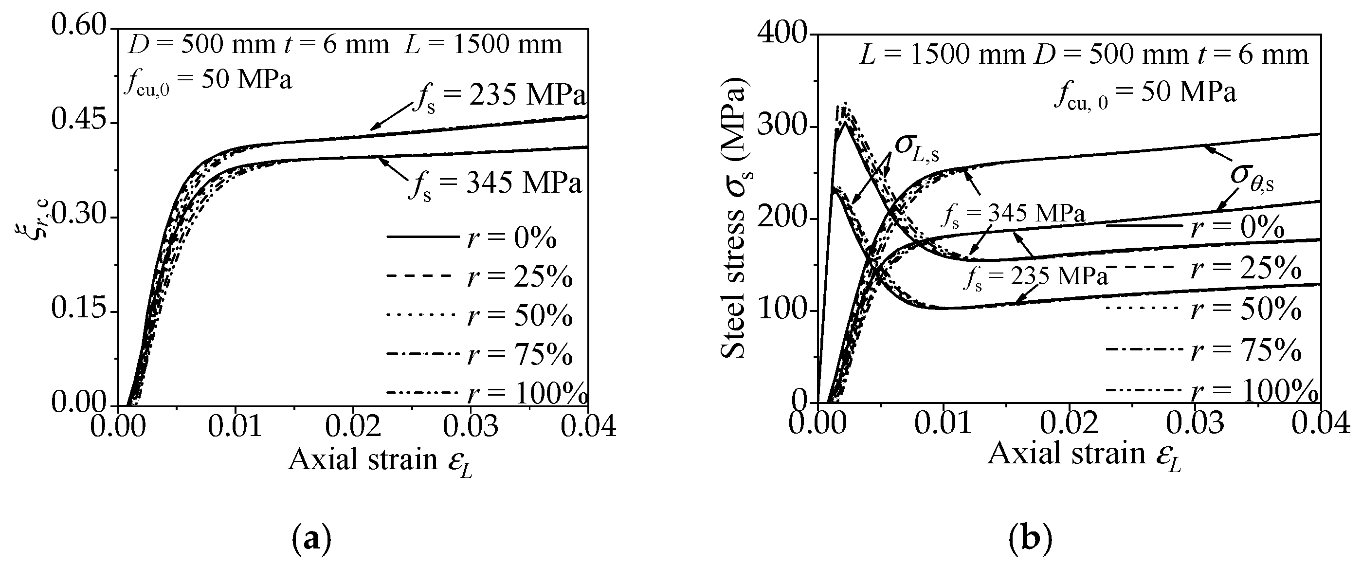
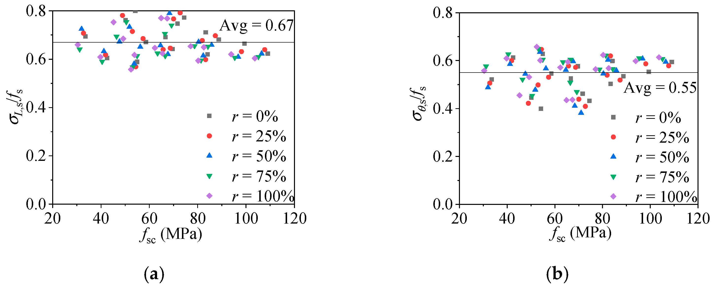
3.2.2. Steel Strength
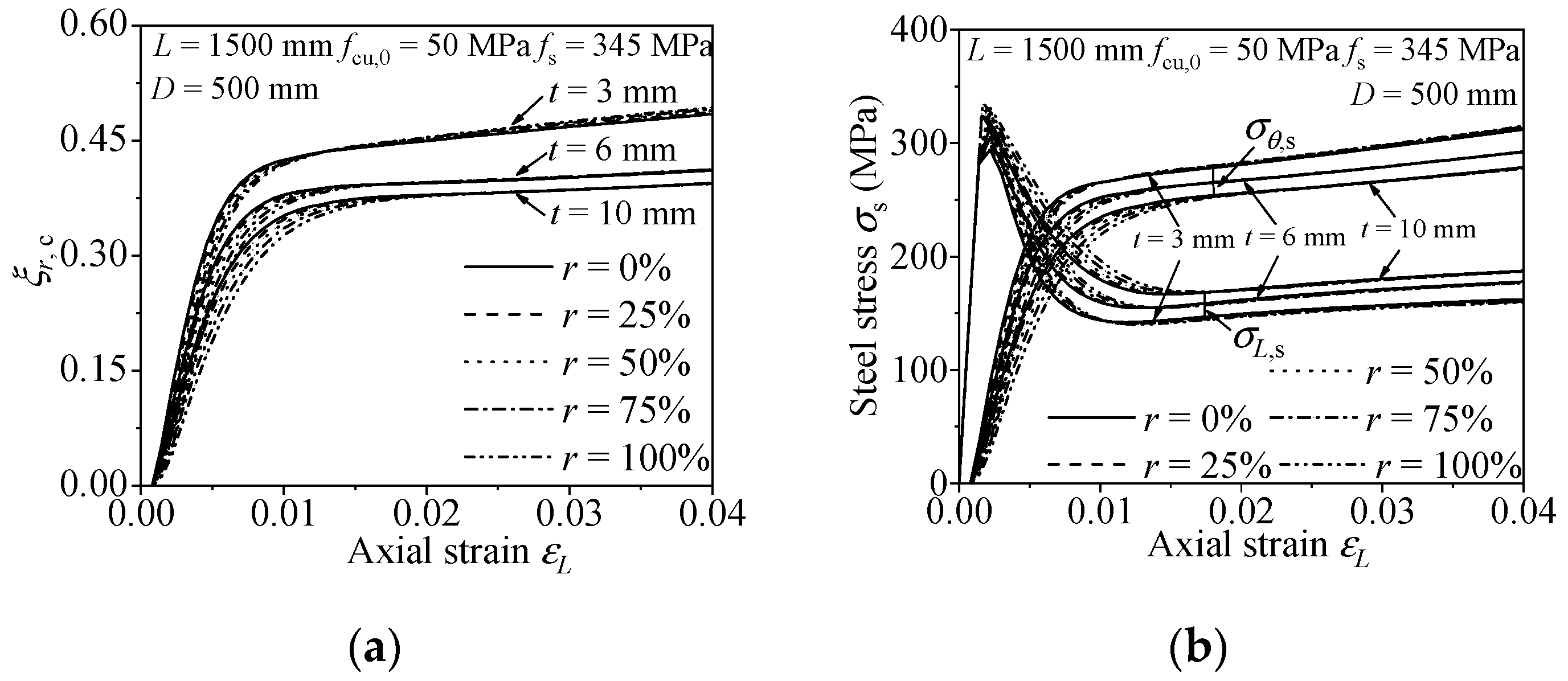
The influence on the confinement effect and efficiency of the RACFCST stub columns caused by diverse steel strength (fs) is shown in Figure 8. The radial concrete confinement coefficient ξr,c of fs = 235 MPa is higher than that of fs = 345 MPa in Figure 8a, and the longitudinal and the lateral stress–strain curve of fs = 235 MPa intersect before those of fs = 345 MPa in Figure 8b. Thus, the high strength steel causes a low efficiency of confinement on the infilled concrete.

3.2.3. Steel Ratio

The influence on the confinement effect and efficiency of the RACFCST stub columns caused by various steel ratios (ρ) is shown in Figure 9. From Figure 9a,b, the increase of steel ratio attenuates the radial concrete confinement coefficient ξr,c and postpones the cross of the longitudinal and the lateral stress–strain curves, which means the decrease of confinement efficiency. In conclusion, a thicker steel tube causes a weaker confinement efficiency on the infilled concrete.

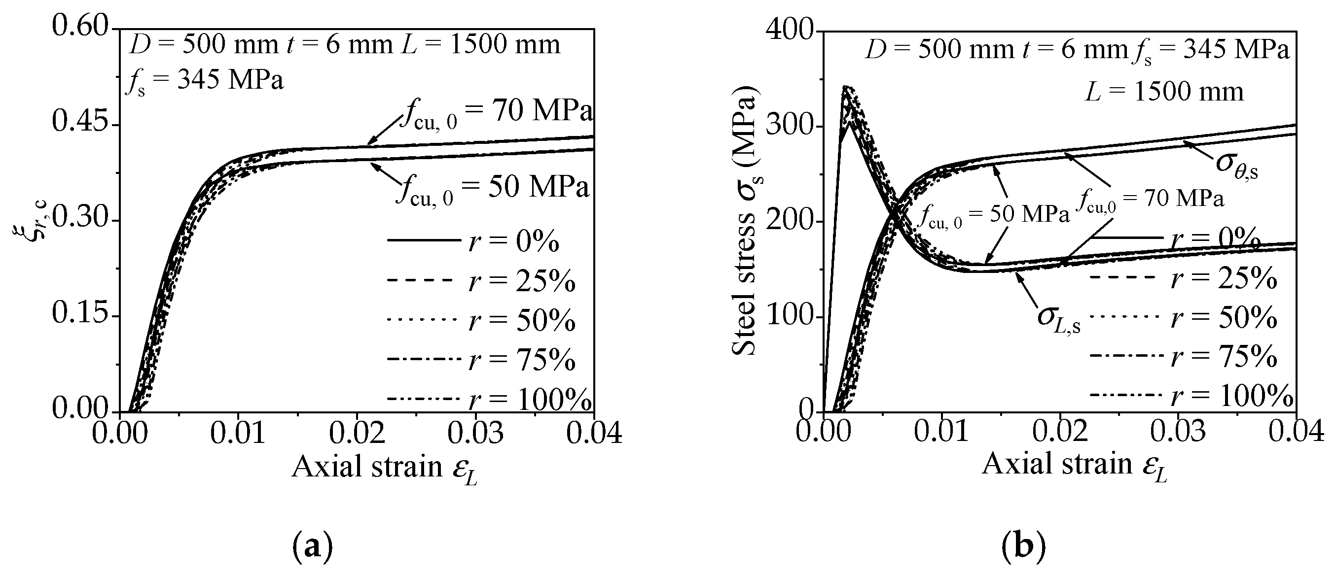
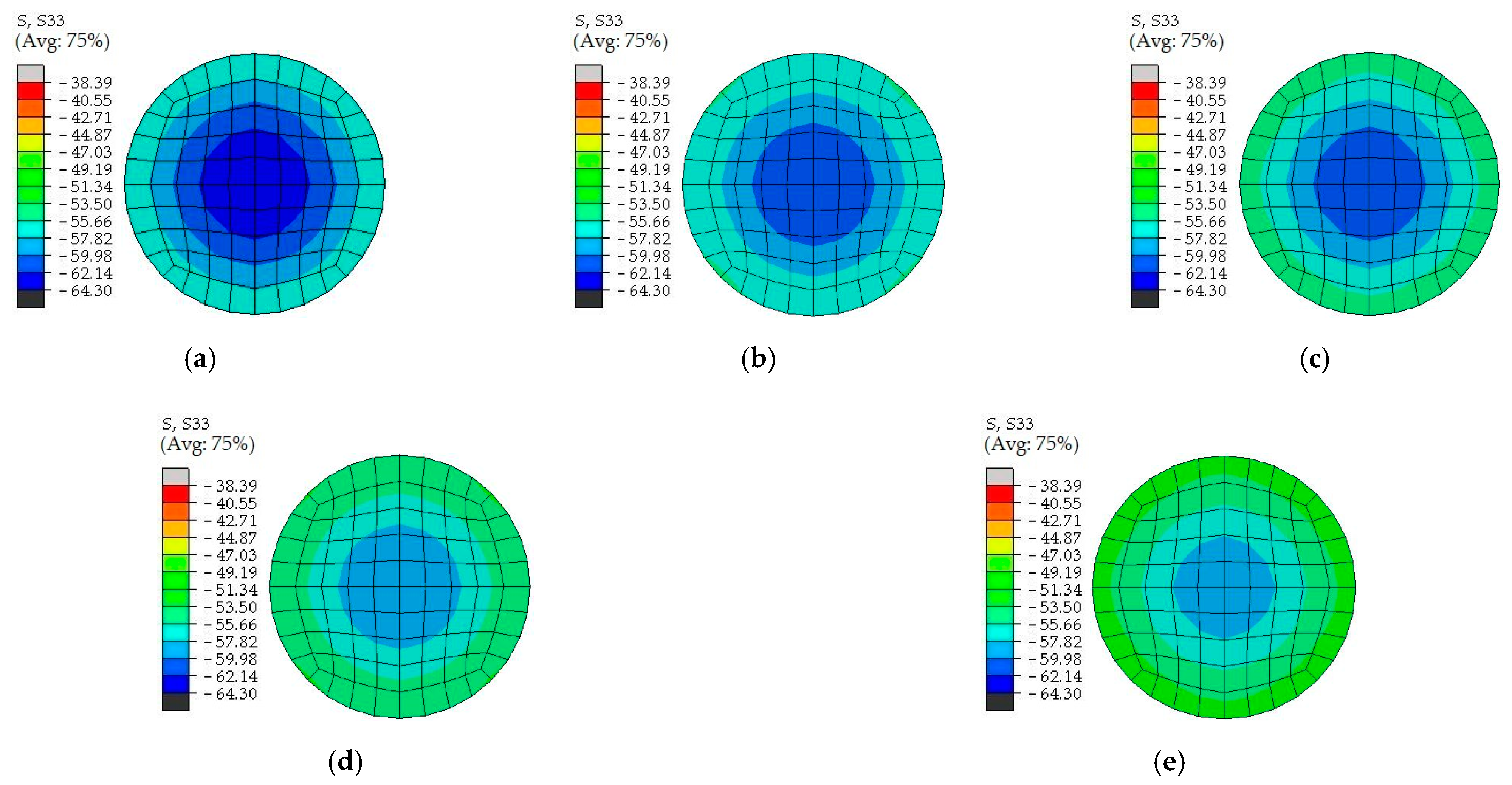
3.2.4. The Replacement Ratio of Recycled Aggregate

Figure 7, Figure 8 and Figure 9 present the influence of a diverse replacement ratio of recycled aggregate (r) on the confinement effect correlation curves. The comparison states follow the mechanical behavior of RACFCST stub columns:
(1)
The increase of replacement ratio of recycled aggregate r results in the radial concrete confinement coefficient ξr,c of RACFCST stub columns being smaller at the initial phase of the loading process. However, at the end of loading, ξr,c with different r tends to be the same.
(2)
The axial stress decreased after reaching the peak point, the transverse stress gradually increased under continuous axial loading, and the axial stress–strain curve intersects with the transverse stress curve in the end. However, the intersection point of the longitudinal and the lateral stress–strain curve is slightly postponed with the increase of the recycled aggregate replacement ratio.
The above observations indicate that the replacement ratio of recycled aggregate r has less of an effect on the confinement effect and efficiency contrasted with material strengths and steel ratio investigated in this paper.

3.3. Contrast of CFCST and RACFCST Stub Columns under Axial Compression

After fixing parameters (D = 500 mm, L = 1500 mm, t = 6 mm, fs = 345 MPa, fcu,0 = 50 MPa) and changing the replacement ratio of recycled aggregate r, the concrete stress nephogram values at the middle height cross-section of CFCST and RACFCST stub columns were obtained by ABAQUS calculation, as shown in Figure 10. The increase replacement ratio of recycled aggregate r slightly weakens the confinement effect of the steel tube, but the reduction is not obvious.
In order to mathematically analyze the constraint effect of concrete-filled steel tubular columns, a simplified diagram (Figure 11) is used in this section to better understand the derivation of theoretical equations. The simplified model abides by the stress distribution and the superposition theory when the infilled concrete reached the ultimate limit state where Ac and As are the cross-sectional areas of the concrete and steel tube, respectively. D and D0 are the diameter of the steel tube and infilled concrete, respectively. The areas of the concrete and steel tube could be expressed as:
{ A c = π D 0 2 4 A s = π ( D 2 D 0 2 ) 4 .

4. Practical Design Formula of Load-Bearing Capacity of RACFCST Stub Columns

4.1. Formulation

According to Figure 11, the relationship between σr,c and σθ,s in the inelastic stage can be expressed as [48]:
σ r , c = ρ 2 ( 1 ρ ) σ θ , s
ρ = D 2 D 0 2 D 2 .
For the RACFCST stub columns, the following expressions were derived. σL,s and σθ,s represents the longitudinal stress and lateral stress of the steel tube, respectively. σL,c and σr,c represents the axial compressive stress and radial stress of core concrete, respectively.
As shown in Figure 12a,b, when RACFCST stub columns reach the ultimate strength (fsc = Nu/Asc, Asc = Ac + As), the average ratio of σL,s and σθ,s of the steel tube could be obtained as:
σ L , s = 0.67 f s
σ θ , s = 0.55 f s .
The longitudinal stress of confined concrete could be given as:
σ L , c = f c + k σ r , c
where k is the coefficient of the lateral pressure and k = 3.4 was suggested herein, according to Ding et al. [48].
Based on the static equilibrium method, the ultimate bearing capacity Nu of RACFCST stub columns under axial compression could be put as:
N u = σ L , c A c + σ L , s A s .
Substituting Equations (7)–(12) into Equation (13), Nu could be obtained as:
N u = f c A c + K f s A s
where K is the proposed confinement coefficient of RACFCST stub columns subjected to the axial load. Based on the aforementioned FE model analysis, the K of the RACFCST stub columns obtained from Equation (13) is 1.61. It worth mentioning that Ding et al. [48] established the equation for the ultimate bearing capacity (Nu = fcAc + 1.7 fsAs) of the CFCST stub column according to the limit equilibrium method, which was validated by 115 CFCST stub columns test results. Meanwhile, Ding et al. [49] combined the FE analysis and the superposition theory to obtain the confinement coefficient K (K = 1.62) of CFCST stub columns as well. This discrepancy between the two methods was considered due to the constitutive relation of the steel tube in the FE analysis, which could not perfectly reflect the stress–strain curves of the steel tube in the test, especially in the hardening stage. According to the existing experimental tests, local buckling could be occasionally observed on the outer steel tube, while the specimen reached the ultimate loading capacity [31], and the hardening of steel enhances the confinement effect of the steel tube on the infilled concrete. Hence, compensating for the confinement effect of the steel tube in FE analysis and combining with the limit equilibrium method and experimental data verification, the confinement coefficient of CFCST stub columns subjected to axial load is recommended as 1.7. The confinement coefficient K of the RACFCST stub columns obtained in this study is close to the confinement coefficient K (K = 1.62) of CFCST stub columns [49] obtained by FE model analysis, and the radial stress–axial strain curves shown in Figure 7, Figure 8 and Figure 9 indicate that the replacement ratio of recycled aggregate has a minor impact on the confinement effect of the steel tube on the infilled RAC at the ultimate state; thereby, the confinement coefficient of RACFCST and CFCST stub columns is unified as 1.7 here for the sake of precision and simplicity.

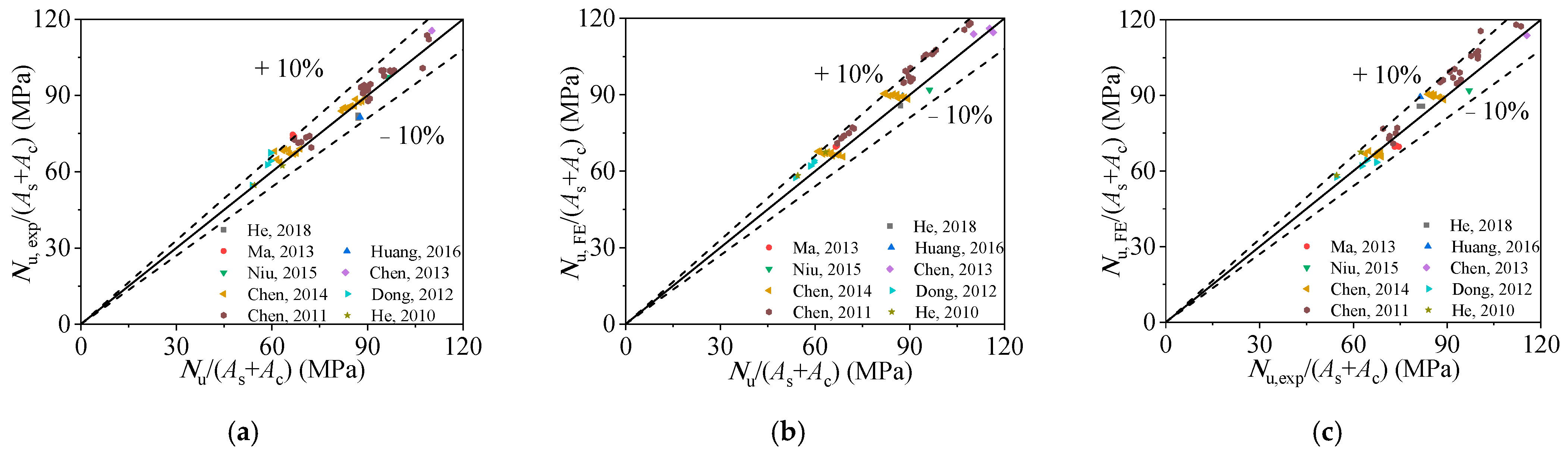
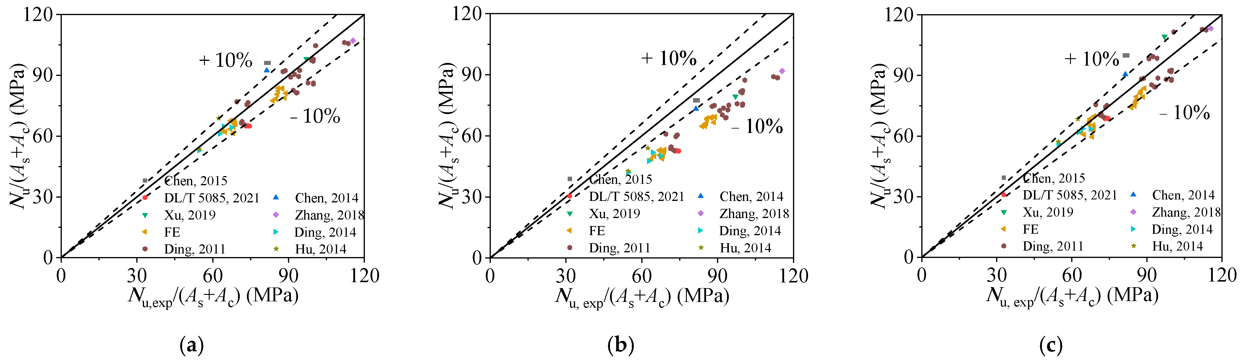
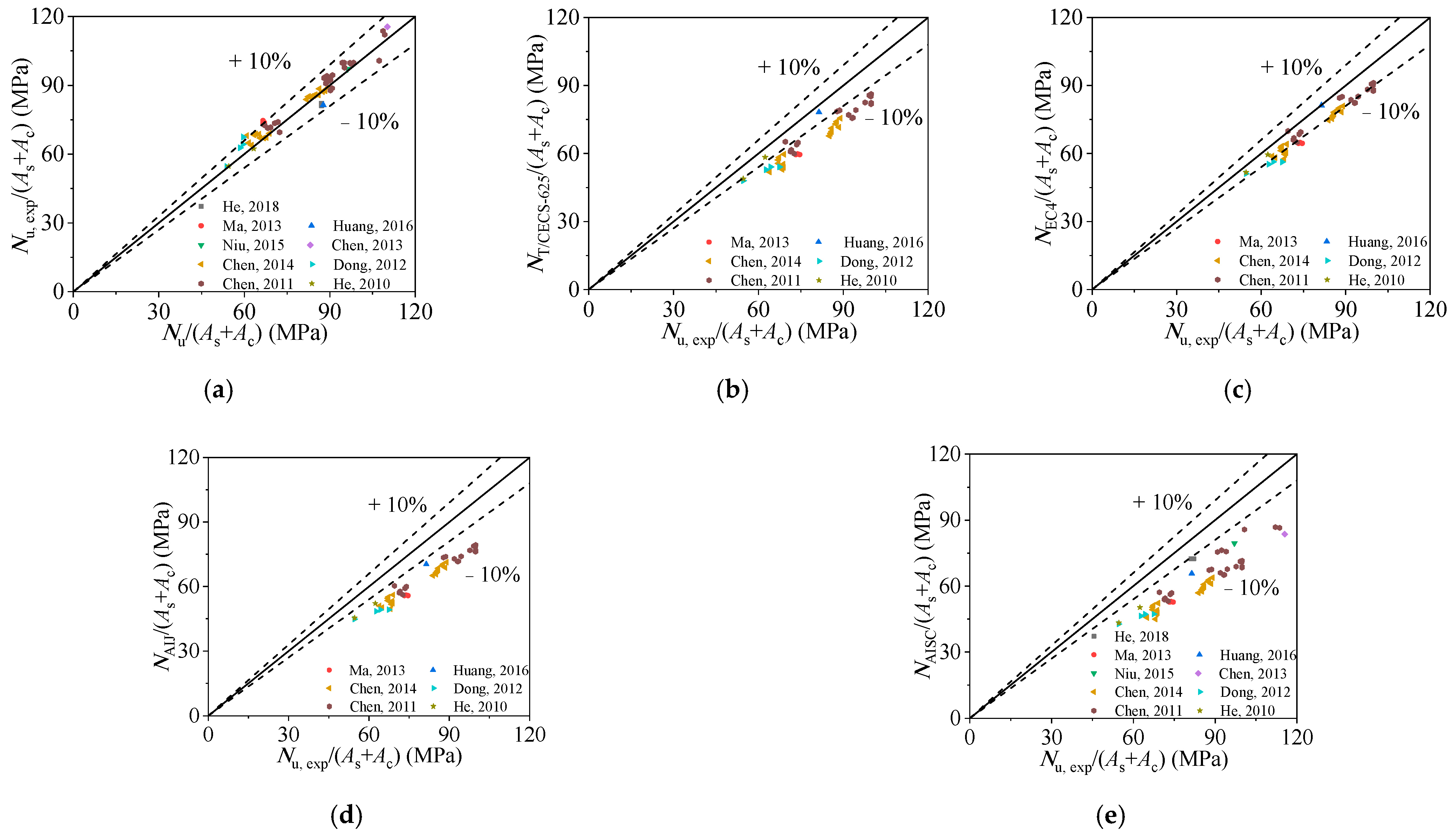
4.2. Formula Validation

Figure 13 and Table 2 compare the ultimate bearing capacity calculated obtained from Equation (13) (Nu), test results (Nu,exp), and FE results (Nu,FE) for RACFCST stub columns under axial loading. For comparison, the average stress of the cross-sectional area of the column specimens (N/(As + Ac)) is used as the horizontal axis. Figure 13a–c show that the average cross-sectional stress calculated by the proposed equation match well with that of Nu,exp and Nu,FE. The mean value of the ratios of Nu,exp/Nu,FE is 0.978 with the corresponding dispersion coefficient of 0.048. The average ratio of Nu,exp to Nu is 1.024 with the corresponding dispersion coefficient of 0.042. The average ratio of Nu,FE to Nu is 1.049 with the corresponding dispersion coefficient of 0.041. As a result, the ultimate axial bearing capacity of RACFCST stub columns calculated by Equation (13) is accurate.

4.3. Comparison of Existing Formulae

In order to visually illustrate the advantages of the proposed equation, it is compared with some current international design codes and well-known design formulae proposed by other scholars. Firstly, as shown in Figure 14 and Table 4 and Table 5, the performance and applicability of the current design codes were investigated. Considering the applicable scope of each design code, as shown in Table 4, the number of calculation examples involved in the calculation is different, as shown in the column “Total” in Table 5. Figure 14 presents the predicted axial-bearing capacity using various design codes and indicates that most of the current codes considerably underestimate the bearing capacity. Meanwhile, the average ratios of Nu,exp to Nu,ACI-318-11, Nu,T/CECS 625-2019, Nu,EC4, Nu,AIJ, and Nu,AISC 360-16 shown in Table 5 are 1.429, 1.188, 1.103, 1.267, and 1.352 with the corresponding dispersion coefficients of 0.060, 0.046, 0.037, 0.037, and 0.069, respectively. Therefore, the proposed formula (Equation (13)) is more precise than the current design codes and has a wider range of applications.
Then, the performance of the proposed design equation was further evaluated by comparing the accuracy of the predicted results using design formulae proposed by other scholars. The details of those formulae are show in Table 6. The predicted results are shown in Figure 15. The average ratios of Nu,exp to Nu,Chen, Z.P., Nu,Chen, M.C., and Nu,Xu, W. are 1.035, 1.268, and 1.025 with the corresponding dispersion coefficients of 0.072, 0.064, and 0.079, respectively. As the result, only the formulae proposed by Xu et al. [24] show a comparable accuracy with the proposed formula (Equation (13)). However, as shown in Table 4, the discreteness of predicted results is relatively larger, and the formulae are more complicated and cumbersome. In general, compared with other scholars’ formulae and international codes, the proposed calculation equation (Equation (13)) is more precise and compendious. Meanwhile, the “confinement effect” is quantified in the derivation of the equation, which explains the influence of the confinement effect on the ultimate bearing capacity more directly.

5. Conclusions

In this paper, numerical study was conducted using the FE models validated by existing experimental results to investigate the confinement effect and confinement efficiency of RACFCST stub columns under axial loading. A simple and practical design equation is proposed to predict the ultimate bearing capacity of RACFCST stub columns. The following conclusions could be stated:
  • The FE models of RACFCST stub columns under axial compression can be modeled utilizing the triaxial RAC plastic-damage and steel constitutive relations. The good agreement between the experimental results and the FE calculation results indicates the validity of the FE model.
  • On the basis of verifying the FE modeling method, parameter analysis was conducted on the full-scale RACFCST stub columns. The analytical results indicate that the recycled aggregate slightly weakened the confinement effect between the steel tube and infilled RAC.
  • The conclusions can be drawn from parametric analysis, the ξr,c–axial strain curves and steel stress–axial strain curves indicate that the materials’ strength (fcu, fs) and specimen dimensions (ρ) impact on the confinement efficiency in the axial loading process. However, the effect of replacement rate of recycled aggregate (r) on the confinement effect and efficiency of RACFCST in the limit state can be ignored.
  • An equation for calculating the ultimate bearing capacity of RACFCST stub columns was proposed by the superposition method. The confinement coefficient (K) of RACFCST axial compression stub columns is 1.7. The proposed equation is more precise and compendious than current international design codes and other scholars’ literature.
There are still some limitations in this paper. The influence of different kinds of recycled aggregates on the bearing capacity of the RACFCST columns and the application of recycled concrete in practical engineering will be carried out in the future.

Author Contributions

Conceptualization, F.L. and F.D.; methodology, E.W., Y.L. and F.L.; software, E.W., Y.L. and Y.X.; validation, E.W. and Y.L.; formal analysis, E.W. and Y.L.; investigation, E.W., Y.L. and Y.X.; resources, Y.L.; data curation, Y.L.; writing—original draft preparation, E.W., Y.L. and F.L.; writing—review and editing, E.W. and F.L.; visualization, E.W. and Y.L.; supervision, F.L. and F.D.; project administration, F.L. and F.D.; funding acquisition, F.L. and F.D. All authors have read and agreed to the published version of the manuscript.

Funding

This research was funded by the National Natural Science Foundation of China (Grant No. 51978664). Science Fund for Distinguished Young Scholars in Hunan Province (Grant No. 2019JJ20029). National Natural Science Foundation of China (Grant No. 52008400).

Institutional Review Board Statement

Not applicable.

Informed Consent Statement

Not applicable.

Data Availability Statement

No new data were created or analyzed in this study. Data sharing is not applicable to this article.

Conflicts of Interest

The authors declared that they have no conflicts of interest to this work. We declare that we do not have any commercial or associative interest that represents a conflict of interest in connection with the work submitted.

References

  1. Mehta, P.K.; Meryman, H. Tools for reducing carbon emissions due to cement consumption. Struct. Mag. 2009, 1, 11–15. [Google Scholar]
  2. Sonawane, T.R.; Pimplikar, S.S. Use of recycled aggregate in concrete. JMCE 2013, 2, 52–59. [Google Scholar]
  3. Oikonomou, N.D. Recycled concrete aggregates. Cem. Concr. Comp. 2005, 27, 315–318. [Google Scholar] [CrossRef]
  4. Xiao, J.Z.; Li, W.G.; Fan, Y.H.; Huang, X. An overview of study on recycled aggregate concrete in China (1996–2011). Constr. Build. Mater. 2012, 31, 364–383. [Google Scholar] [CrossRef]
  5. Manzi, S.; Mazzotti, C.; Bignozzi, M.C. Short and long-term behavior of structural concrete with recycled concrete aggregate. Cem. Concr. Compos. 2013, 37, 312–318. [Google Scholar] [CrossRef]
  6. Ajdukiewicz, A.; Kliszczewicz, A. Influence of recycled aggregates on mechanical properties of HS/HPC. Cem. Concr. Compos. 2002, 24, 269–279. [Google Scholar] [CrossRef]
  7. Liu, Y.C.; Lyu, F.; Ding, F.X.; Wang, E.; Xu, Y.L.; Yuan, T.; Deng, C.; Luo, C. Numerical study of confinement effect and efficiency of concentrically loaded RACFRST stub columns. Front. Mater. 2021, 8, 630774. [Google Scholar] [CrossRef]
  8. Xiao, J.Z.; Li, J.B.; Zhang, C. Mechanical properties of recycled aggregate concrete under uniaxial loading. Cem. Concr. Res. 2005, 35, 1187–1194. [Google Scholar] [CrossRef]
  9. Javier Zega, C.; Di Maio, A.A. Recycled concrete made with different natural coarse aggregates exposed to high temperature. Constr. Build. Mater. 2009, 23, 2047–2052. [Google Scholar] [CrossRef]
  10. Katz, A. Treatments for the improvement of recycled aggregate. J. Mater. Civ. Eng. 2004, 16, 597–603. [Google Scholar] [CrossRef]
  11. Li, Y.; Fu, T.H.; Wang, R.J.; Li, Y. An assessment of microcracks in the interfacial transition zone of recycled concrete aggregates cured by CO2. Constr. Build. Mater. 2020, 236, 11. [Google Scholar] [CrossRef]
  12. Hasan, D.; Özgür, Ç. Influence of basalt fiber on physical and mechanical properties of treated recycled aggregate concrete. Constr. Build. Mater. 2020, 254, 119216. [Google Scholar] [CrossRef]
  13. Wang, Y.G.; Li, S.P.; Hughes, P.; Fan, Y.H. Mechanical properties and microstructure of basalt fibre and nano-silica reinforced recycled concrete after exposure to ele-vated temperatures. Constr. Build. Mater. 2020, 247, 118561. [Google Scholar] [CrossRef]
  14. Gao, C.; Huang, L.; Yan, L.B.; Jin, R.Y.; Chen, H.Z. Mechanical properties of recycled aggregate concrete modified by nano-particles. Constr. Build. Mater. 2020, 241, 118030. [Google Scholar] [CrossRef]
  15. Wang, Y.Y.; Chen, J.; Geng, Y. Testing and analysis of axially loaded normal-strength recycled aggregate concrete filled steel tubular stub columns. Eng. Struct. 2015, 86, 192–212. [Google Scholar] [CrossRef]
  16. Chen, Z.P.; Ke, X.J.; Xue, J.Y.; Su, Y.S. Mechanical performance and ultimate bearing capacity calculation of steel tube confined recycled coarse aggregate concrete. Chin. Civ. Eng. J. 2013, 46, 70–77. [Google Scholar]
  17. Yang, Y.F.; Han, L.H. Experimental behaviour of recycled aggregate concrete filled steel tubular columns. J. Constr. Steel. Res. 2006, 62, 1310–1324. [Google Scholar] [CrossRef]
  18. Dong, J.F.; Wang, Q.Y.; Guan, Z.W. Material and structural response of steel tube confined recycled earthquake waste concrete subjected to axial compression. Mag. Concr. Res. 2016, 68, 271–282. [Google Scholar] [CrossRef]
  19. Zhang, X.G.; Chen, Z.P.; Xue, J.Y.; Su, Y.S.; Fan, J. Experimental study and mechanical behavior analysis of recycled aggregate concrete filled steel tubular long columns under axial compression. J. Build. Struc. 2012, 33, 12–20. [Google Scholar]
  20. Zhang, X.G.; Chen, Z.G.; Wang, J.M.; Xue, J.Y.; Zheng, S.F.; Li, Q.L.; Su, Y.S. Study on eccentric compression behaviors of recycled aggregate concrete filled steel tubular long columns. Eng. Mech. 2013, 30, 331–340. [Google Scholar]
  21. Chen, Z.P.; He, T.Y.; Xu, J.J.; Liu, X. Performance and bearing capacity of recycled aggregate concrete-filled circular steel tube-column under axial compression. J. Guangxi Univ. Nat. Sci. Ed. 2015, 40, 897–907. [Google Scholar] [CrossRef]
  22. DL/T 5085-2021. Code for Design of Steel-Concrete Composite Structure; National Energy Adiministration: Beijing, China, 2021.
  23. Chen, M.C.; Liu, J.J.; Huang, H. Study on circle recycled aggregate concrete-filled steel tube under axial compression. Concrete 2014, 12, 43–48. [Google Scholar]
  24. Xu, W.; Bai, Y.; Luo, D. Calculation methods for recycled aggregate concrete filled circular steel tubular short columns. J. Shenyang Univ. Tech. 2019, 41, 339–343. [Google Scholar]
  25. Lyu, W.Q.; Han, L.H.; Hou, C.J.E.S. Axial compressive behaviour and design calculations on recycled aggregate concrete-filled steel tubular (RAC-FST) stub columns. Eng. Struct. 2021, 241, 112452. [Google Scholar] [CrossRef]
  26. Zhang, T.; Ding, F.X.; Wang, L.P.; Liu, X.M.; Jiang, G.S. Behavior of polygonal concrete-filled steel tubular stub columns under axial loading. Steel Compos. Struct. 2018, 28, 573–588. [Google Scholar] [CrossRef]
  27. Hibbitt, B.K.D.; Sorensen, P. ABAQUS Standard User’s and Reference Manuals; Version 6.14; Dassault Systèmes: Johnston, RI, USA, 2014. [Google Scholar]
  28. Ding, F.X.; Fang, C.J.; Gong, Y.Z.; Yu, Z.W.; Hu, L.N. Unified Calculation Method of Uniaxial Mechanical Performance Index of Recycled Concrete. J. Arch. Civ. Eng. 2014, 31, 16–22. [Google Scholar]
  29. Ding, F.X.; Ying, X.Y.; Zhou, L.C.; Yu, Z.W. Unified calculation method and its application in determining the uniaxial mechanical properties of concrete. Front. Struct. Civ. Eng. 2011, 5, 381–393. [Google Scholar] [CrossRef]
  30. Hu, L.N. Mechanical Performance of Recycled Concrete-Filled Circular Steel Tubular Column; Central South University: Changsha, China, 2014. [Google Scholar]
  31. Ding, F.X.; Zhu, J.; Cheng, S.S.; Liu, X.M. Comparative study of stirrup-confined circular concrete-filled steel tubular stub columns under axial loading. Thin Walled Struct. 2018, 123, 294–304. [Google Scholar] [CrossRef] [Green Version]
  32. Lu, D.R.; Wang, W.J.; Ding, F.X.; Liu, X.M.; Fang, C.J. The impact of stirrups on the composite action of concrete-filled steel tubular stub columns under axial loading. Structures 2021, 30, 768–802. [Google Scholar] [CrossRef]
  33. Ding, F.X.; Wang, W.J.; Lu, D.R.; Liu, X.M. Study on the behavior of concrete-filled square double-skin steel tubular stub columns under axial loading. Structures 2020, 23, 665–676. [Google Scholar] [CrossRef]
  34. Ding, F.X.; Wang, W.J.; Liu, X.M.; Wang, L.P.; Sun, Y. Mechanical behavior of outer square inner circular concrete filled dual steel tubular stub columns. Steel Compos. Struct. 2021, 38, 305–317. [Google Scholar] [CrossRef]
  35. Ding, F.X.; Sheng, S.J.; Yu, Y.J.; Yu, Z.W. Mechanical behaviors of concrete-filled rectangular steel tubular under pure torsion. Steel Compos. Struct. 2019, 31, 291–301. [Google Scholar] [CrossRef]
  36. Ding, F.X.; Fu, Q.; Wen, B.; Zhou, Q.S.; Liu, X.M. Behavior of circular concrete-filled steel tubular columns under pure torsion. Steel Compos. Struct. 2018, 26, 501–511. [Google Scholar] [CrossRef]
  37. Ding, F.X.; Luo, L.; Wang, L.P.; Cheng, S.S.; Yu, Z.W. Pseudo-static tests of terminal stirrup-confined concrete-filled rectangular steel tubular columns. J. Constr. Steel. Res. 2018, 144, 135–152. [Google Scholar] [CrossRef] [Green Version]
  38. He, Z.J.; Tian, L.L.; Zhang, Z.J.; Zhang, X.S. Study of recycled aggregate concrete filled steel tubular column under axial load and its core recycled concrete under multi-axial mechanics. Build. Struct. 2018, 48, 560–566. [Google Scholar] [CrossRef]
  39. Ma, J. Static Behavior of Recycled Aggregate Concrete Filled Circular Steel Tubular Columns; Harbin Institute of Technology: Harbin, China, 2013. [Google Scholar]
  40. Huang, H.; Guo, X.Y.; Chen, M.Y. Comparative experimental research on recycled aggregate concrete filled steel tubular columns subjected to axial compression. Build. Struct. 2016, 46, 34–39 + 49. [Google Scholar]
  41. Niu, H.C.; Cao, W.L. Full-scale testing of high-strength RACFST columns subjected to axial compression. Mag. Concr. Res. 2015, 67, 257–270. [Google Scholar] [CrossRef]
  42. Chen, J.; Zeng, L. Experiment on mechanical performance of axial compression of recycled concrete-filled steel-tubular stub columns. J. Lanzhou Univ. Tech. 2013, 39, 112–116. [Google Scholar] [CrossRef]
  43. Chen, Z.P.; Xu, J.J.; Xue, J.Y.; Su, Y.S. Performance and calculations of recycled aggregate concrete-filled steel tubular (RACFST) short columns under axial compression. Int. J. Steel Struct. 2014, 14, 31–42. [Google Scholar] [CrossRef]
  44. Dong, J.F.; Hou, M.; Wang, Q.Y.; Yuan, S.C. Experimental research on the mechanical behaviour of recycled aggregate concrete and its short columns. In Proceedings of the Third National Symposium on Recycled Concrete, Qingdao, China, 6–8 September 2012; pp. 193–199. [Google Scholar]
  45. Chen, J. Static Behavior of Recycled Aggregate Concrete Filled Steel Tubular Stub Columns Under Axial Compression Loading; Harbin Institute of Technology: Harbin, China, 2011. [Google Scholar]
  46. He, D.; Wang, Q.Y.; Qiu, C.Z.; Shi, X.S.; Dong, J.F. The theoretical and experimental analysis of load-deformation of recycled concrete filled steel tubes subjected axial compression. In Proceedings of the Sichuan Society in Mech.: J. Sichuan Univ. (Eng. Science Edition), Chengdu, China, 1 September 2010; pp. 55–59. [Google Scholar]
  47. Chen, Z.Y.; Zhu, J.Q.; Wu, P.G. High-Strength Concrete and Its Applications; Tsinghua University Press: Beijing, China, 1992. [Google Scholar]
  48. Ding, F.X.; Yu, Z.W.; Bai, Y.; Gong, Y.Z. Elasto-plastic analysis of circular concrete-filled steel tube stub columns. J. Constr. Steel. Res. 2011, 67, 1567–1577. [Google Scholar] [CrossRef]
  49. Ding, F.X.; Yin, Y.X.; Mao, J.F.; Wang, L.P.; Yu, Y.J.; Luo, L.; Yu, Z.W. Analytical behaviors of concrete-filled circular stainless steel tubular (CFCSST) stub columns under axial loading. Structures 2019, 19, 277–285. [Google Scholar] [CrossRef]
  50. ACI-318-Building Code Requirements for Structural Concrete and Commentary ACI Committee 318; American Concrete Institute: Detroit, MI, USA, 2011.
  51. T/CECS 625-Technical Specification for Recycled Aggregate Concrete-Filled Steel Tubular Structures; Architecture & Building Press: Beijing, China, 2019.
  52. Eurocode Design of Steel Composite Steel and Concrete Structures, Part 1-1, General Rules And Rules for Building, BS EN 1994-1-1; British Standards Institution: London, UK, 2004.
  53. AIJ. Recommendations for Design and Construction of Concrete Filled Steel Tubular Structures; Architectural Institute of Japan: Tokyo, Japan, 1997. [Google Scholar]
  54. AISC. Specification for Structural Steel Buildings. ANSI/AISC 360-16; American Institute of Steel Construction: Chicago, IL, USA, 2016. [Google Scholar]
Figure 1. Axial load–mesh size curve.
Materials 15 00154 g001
Figure 2. Meshing and boundary conditions of the RACFCST stub column FE model.
Materials 15 00154 g002
Figure 3. Diagram of confined and unconfined plastic-damage model of RAC: (a) unconfined strain–stress relation of RAC with different replacement ratio; (b) confined stress–strain relation of RAC with different replacement ratio.
Materials 15 00154 g003
Figure 4. Constitutive relations of steel tube with different yield strength.
Materials 15 00154 g004
Figure 5. Comparison of FE and experimental load–strain curves: (a) reference [38]; (b) reference [41]; (c) reference [44].
Materials 15 00154 g005
Figure 6. Influence of various parameters: (a) concrete strength; (b) steel strength; (c) steel ratio.
Materials 15 00154 g006
Figure 7. Effect of concrete strength on confinement effect of RACFCST stub columns: (a) radial stress–axial strain curves; (b) ξr,c–axial strain curves.
Materials 15 00154 g007
Figure 8. Effect of steel strength on confinement effect of RACFCST stub columns: (a) radial stress–axial strain curves; (b) ξr,c–axial strain curves.
Materials 15 00154 g008
Figure 9. Effect of steel ratio on the confinement effect of RACFCST stub columns: (a) radial stress–axial strain curves; (b) ξr,c–axial strain curves.
Materials 15 00154 g009
Figure 10. Comparison of stress nephogram of infilled concrete at the mid-section for CFCST and RACFCST stub columns: (a) r = 0%; (b) r = 25%; (c) r = 50%; (d) r = 75%; (e) r = 100%.
Materials 15 00154 g010
Figure 11. Simplified stress distribution model at the mid-height section of CFCST stub columns.
Materials 15 00154 g011
Figure 12. Axial compressive stress and transverse stress of RACFST stub column: (a) average ratio of axial compressive stress to the yield stress of the steel tube; (b) average ratio of tensile transverse stress to the yield stress of the steel tube.
Materials 15 00154 g012
Figure 13. Comparisons of experimental results and FE results with Equation (13): (a) comparison of ultimate bearing stress obtained from test results and Equation (13); (b) comparison of ultimate bearing stress obtained from FE results and Equation (13); (c) comparison of ultimate bearing stress obtained from FE results and test results.
Materials 15 00154 g013
Figure 14. Comparison of experimental results and design methods’ results: (a) comparison of ultimate bearing stress obtained from test results and ACI-318-11 [50]; (b) comparison of ultimate bearing stress obtained from test results and T/CECS 625-2019 [51]; (c) comparison of ultimate bearing stress obtained from test results and EC4 [52]; (d) comparison of ultimate bearing stress obtained from test results and AIJ [53]; (e) comparison of ultimate bearing stress obtained from test results and AISC 360-16 [54].
Materials 15 00154 g014
Figure 15. Comparison of experimental results and design methods’ results: (a) comparison of ultimate bearing stress obtained from test results and Reference [16]; (b) comparison of ultimate bearing stress obtained from test results and Reference [23]; (c) comparison of ultimate bearing stress obtained from test results and Reference [24].
Materials 15 00154 g015
Table 1. Plastic damage parameters of the triaxial constitutive model of RAC.
Dilation AngleEccentricityfb0/fc0KViscosity Parameter
400.11.2250.66670.005
Table 2. Comparison of loading bearing capacity obtained from experimental and predicted results.
SpecimensRef.D × t ×  L
(mm)
rfcur150
(MPa)
fs
(MPa)
Nu,exp
(kN)
Nu,FE
(kN)
Nu,exp/Nu,FENu,exp/NuNu,FE/Nu
AC-6-1[38]219 × 3.50 × 6000.569.213133055.003224.510.9470.9380.990
AC-6-2[38]219 × 3.50 × 6000.569.213133093.003224.510.9590.9500.990
AC-6-3[38]219 × 3.50 × 6000.569.213133073.003224.510.9530.9440.990
CFST3-0-1-8-a[39]138 × 2.72 × 420140.52299.41104.001047.601.0541.0931.037
CFST3-0-1-8-b[39]138 × 2.69 × 420140.52299.41115.001040.981.0711.1111.037
CFST3-0-1-8-c[39]138 × 2.69 × 420140.52299.41095.001040.981.0521.0911.037
C-S-R[40]165 × 3.54 × 4800.550.003681739.941909.810.9110.9251.015
C1[41]508 × 8.76 × 1500172.36355.819,662.2018,617.91.0560.9980.945
C1[42]127 × 4.20 × 3900.372.06298.31552.501448.781.0721.0510.981
C2[42]127 × 4.20 × 3900.670.38298.31568.001468.971.0671.0701.002
C3[42]127 × 4.20 × 390163.89298.31462.501441.011.0151.0401.025
CA-1[43]88 × 2.50 × 2850.129.14342.7517.53547.570.9451.0311.091
CA-2[43]88 × 2.50 × 2850.228.20342.7509.70545.920.9341.0241.097
CA-3[43]88 × 2.50 × 2850.332.36342.7522.24544.090.9601.0111.053
CA-4[43]88 × 2.50 × 2850.433.82342.7521.73542.070.9620.9971.036
CA-5[43]88 × 2.50 × 2850.531.51342.7519.93539.670.9631.0131.052
CA-6[43]88 × 2.50 × 2850.630.33342.7517.23537.340.9631.0181.058
CA-7[43]88 × 2.50 × 2850.735.86342.7530.88534.810.9930.9951.002
CA-8[43]88 × 2.50 × 2850.836.96342.7533.13531.961.0020.9890.987
CA-9[43]88 × 2.50 × 2850.934.30342.7538.08529.051.0171.0211.004
CA-10[43]88 × 2.50 × 285138.43342.7540.96525.881.0290.9900.962
CB-1[43]112 × 2.00 × 3600.129.14357.2639.63669.040.9561.0541.102
CB-2[43]112 × 2.00 × 3600.228.2357.2670.41667.081.0051.1171.111
CB-3[43]112 × 2.00 × 3600.332.36357.2677.64664.941.0191.0721.052
CB-4[43]112 × 2.00 × 3600.433.82357.2676.59662.591.0211.0511.029
CB-5[43]112 × 2.00 × 3600.531.51357.2673.65659.921.0211.0761.054
CB-6[43]112 × 2.00 × 3600.630.33357.2629.16657.430.9571.0191.064
CB-7[43]112 × 2.00 × 3600.735.86357.2660.00655.001.0080.9990.991
CB-8[43]112 × 2.00 × 3600.836.96357.2662.73652.161.0160.9890.973
CB-9[43]112 × 2.00 × 3600.934.30357.2660.09649.791.0161.0161.000
CB-10[43]112 × 2.00 × 360138.43357.2679.68646.941.0510.9960.948
C1-1[44]114 × 1.80 × 4000.2540.08300.0656.00655.181.0011.0781.077
C2-1[44]114 × 1.80 × 4000.540.11300.0688.00647.421.0631.1281.062
C3-1[44]114 × 1.80 × 4000.7538.86300.0640.00632.671.0121.0651.053
C4-1[44]114 × 1.70 × 400135.02300.0557.00587.280.9481.0071.061
cfst8-30-0.5-1[45]140 × 2.71 × 4200.544.4309.01131.001153.390.9811.0351.056
cfst8-30-0.5-2[45]140 × 2.79 × 4200.544.4309.01139.001186.130.9601.0271.069
cfst8-30-0.5-3[45]140 × 2.83 × 4200.544.4309.01070.001180.900.9060.9571.057
cfst8-30-1-1[45]140 × 2.80 × 420141.1309.01102.001136.380.9701.0261.058
cfst8-30-1-2[45]140 × 2.73 × 420141.1309.01098.001121.570.9791.0361.059
cfst8-30-1-3[45]140 × 2.64 × 420141.1309.01118.001091.541.0241.0741.049
cfst8-50-1-1[45]140 × 2.72 × 420165.0309.01447.001524.470.9491.0561.113
cfst8-50-1-2[45]140 × 2.69 × 420165.0309.01398.001528.150.9151.0251.120
cfst8-50-1-3[45]140 × 2.81 × 420165.0309.01421.001546.020.9191.0241.114
cfst12-30-0.5-1[45]140 × 3.85 × 4200.544.4335.31365.001477.940.9240.9741.055
cfst12-30-0.5-2[45]140 × 3.86 × 4200.544.4335.31453.001481.020.9811.0351.055
cfst12-30-0.5-3[45]140 × 3.81 × 4200.544.4335.31351.001465.910.9220.9701.053
cfst12-30-1-1[45]140 × 3.96 × 420141.1335.31414.001493.010.9471.0181.074
cfst12-30-1-2[45]140 × 3.85 × 420141.1335.31437.001459.930.9841.0531.070
cfst12-30-1-3[45]140 × 3.84 × 420141.1335.31433.001456.810.9841.0521.069
cfst12-50-1-1[45]140 × 3.78 × 420165.0335.31550.001777.140.8720.9381.076
cfst12-50-1-2[45]140 × 3.92 × 420165.0335.31725.001816.210.9501.0261.080
cfst12-50-1-3[45]140 × 3.88 × 420165.0335.31749.001806.760.9681.0451.080
cfst15-30-0.5-1[45]133 × 4.57 × 4000.544.4302.01385.001471.080.9411.0241.088
cfst15-30-0.5-2[45]133 × 4.61 × 4000.544.4302.01377.001481.140.9301.0131.090
cfst15-30-0.5-3[45]133 × 4.66 × 4000.544.4302.01387.001493.710.9291.0131.091
cfst15-30-1-1[45]133 × 4.56 × 400141.1302.01386.001453.040.9541.0511.102
cfst15-30-1-2[45]133 × 4.61 × 400141.1302.01387.001466.150.9461.0451.104
cfst15-30-1-3[45]133 × 4.62 × 400141.1302.01357.001467.430.9251.0211.104
C2-1[46]114 × 1.84 × 3960.543.9300.0636.50688.420.9250.9821.062
C4-2[46]114 × 1.70 × 401135.9300.0557.50594.730.9370.9941.061
Mean 0.9781.0241.049
COV. 0.0480.0420.041
Table 3. Material and geometric properties of specimens for FE parametric study.
D (mm)L (mm)t (mm)rfcu,0 (MPa)fs (MPa)
500150030.00, 0.25, 0.50, 0.75, 1.0030, 50235
500150030.00, 0.25, 0.50, 0.75, 1.0050, 70345
500150030.00, 0.25, 0.50, 0.75, 1.0070420
500150060.00, 0.25, 0.50, 0.75, 1.0030, 50235
500150060.00, 0.25, 0.50, 0.75, 1.0050, 70345
500150060.00, 0.25, 0.50, 0.75, 1.0070420
5001500100.00, 0.25, 0.50, 0.75, 1.0030, 50235
5001500100.00, 0.25, 0.50, 0.75, 1.0050, 70345
5001500100.00, 0.25, 0.50, 0.75, 1.0070420
Table 4. Range of applicability of design equations for circular CFST/RACST columns.
CodeYield Strength of Steel (MPa)Compressive Strength of Concrete (MPa)Diameter to Thickness Ratio
ACI-318-11 [50]AllAll 8 E s / f y
T/CECS 625-2019 [51] 235 ≤ fy ≤ 46030 ≤ fcur,150 ≤ 50≤135(235/fy)
EC4 (2004) [52]235 ≤ fy ≤ 46020 ≤ fc,150 ≤ 50 or 25 ≤ fcu,150 ≤ 60≤90(235/fy)
AIJ (1997) [53]235 ≤ fy ≤ 355fc,100 ≤ 58.8≤1.5(23500/F)
AISC 360-16 (2016) [54]fy ≤ 52521 ≤ f c ≤ 69≤0.31(Es/fy)
Table 5. Summary of available formulae in well-known international codes.
ReferenceFormulaeRemarksTotalAverage Values
(Nu,exp/Nu,ref)
Dispersion Coefficient
ACI-318-11 (2011) [50] N u , ACI = A s f s + 0.85 f c A c Circular611.4290.060
T/CECS 625-2019 [51] N u , T/CECS625-2019 = f s c , r ( A c + A s ) f sc , r = ( 1.14 + 1.02 ξ r , o ) f c , r ξ r , o = A s f A c f c , r Circular441.1880.046
EC4 (2004) [52] N u , EC 4 = η a A s f y + A c f c ( 1 + η c t D f y f c ) η a = 0.25 ( 3 + 2 λ ¯ ) 1.0 ; η c = 4.9 18.5 λ ¯ + 17 λ ¯ 2 1.0 ; λ ¯ = N p l , R k N c r ; N p l , R k = A s f y + A c f c N c r = π 2 ( E s I s + 0.6 E c I c ) L 2 Circular481.1030.037
AIJ (1997) [53] N u , AIJ = γ c f c A c + ( 1 + η ) f y A s η = 0.27 , γ c = 0.85 Circular481.2670.037
Table 6. Summary of available formulae in other scholars’ literature.
ReferenceFormulaeRemarksTotalAverage Values (Nu,exp/Nu,ref)Dispersion Coefficient
Chen, Z. P.
[16]
N u = η f ck A c ( 1 + 0.99 ξ + 1.11 ξ ) ξ = A s f A c f ck , η = 0.901 + 0.084 r 0.154 r 2 Circular611.0350.072
Chen, M.C.
[23]
N u = f scy r ( A c + A s ) , f s c y r = f scy / k f s c y = ( 1.14 + 1.02 ξ ) f c k , ξ = A s f A c f c k = A ( e ξ ) 2 + B e ξ + C A = 0.1059 r + 0.0066 B = 0.12 r + 0.0021 , C = 0.054 r + 1.0044 Circular611.2680.064
Xu, W.
[24]
N u = N u,GB50936-2014 / θ N u,GB50936-2014 = f sc ( A s + A c ) , θ = 0.904 + 0.012 r f sc = ( 1.212 + B ξ + C ξ 2 ) f c ,   ξ = A s f A c f c B = 0.176 f / 213 + 0.974 , C = 0.104 f c / 14.4 + 0.031 Circular611.0250.079
Publisher’s Note: MDPI stays neutral with regard to jurisdictional claims in published maps and institutional affiliations.

