
Gas Metal Arc Welding Modes in Wire Arc Additive Manufacturing of Ti-6Al-4V


 ,
,  ,
,
Abstract
1. Introduction
2. Materials and Methods
3. Results and Discussion
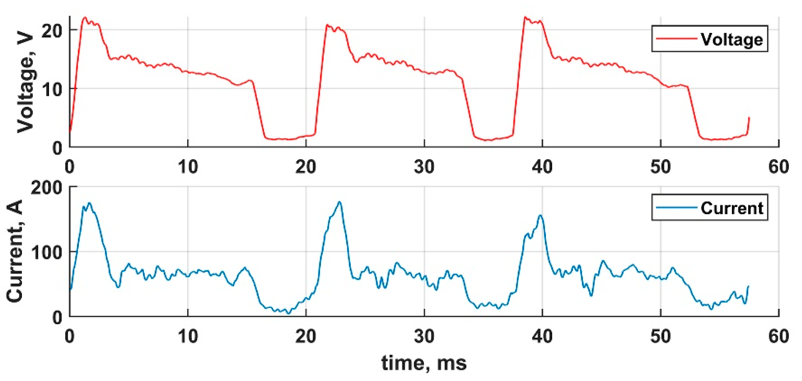
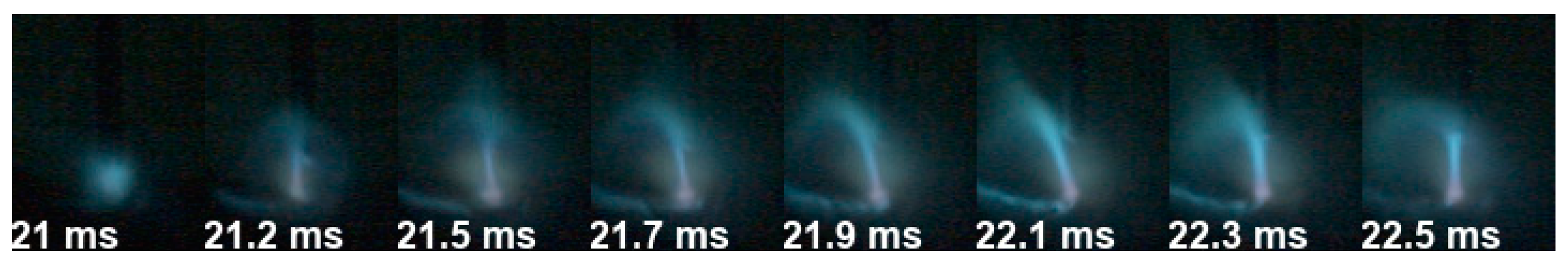
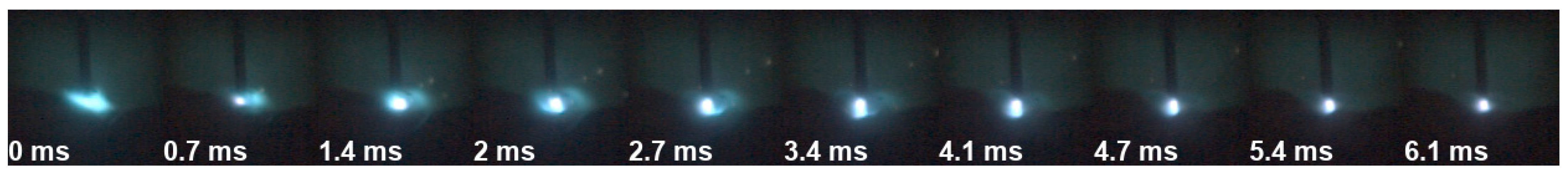
3.1. CMT
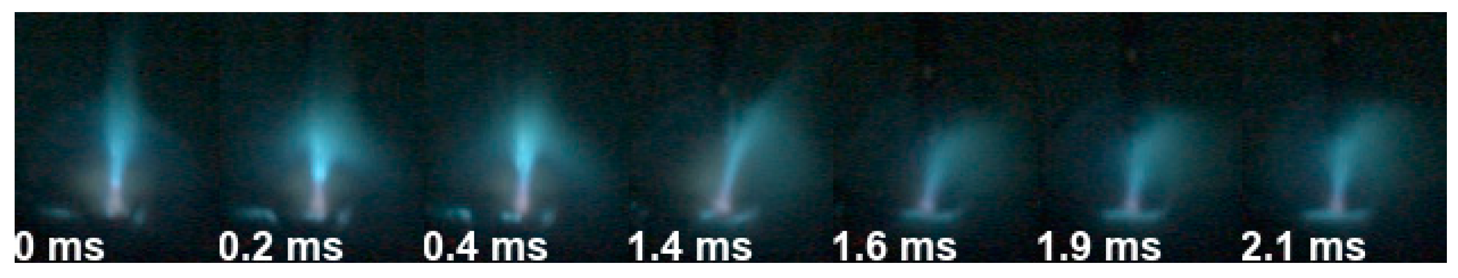
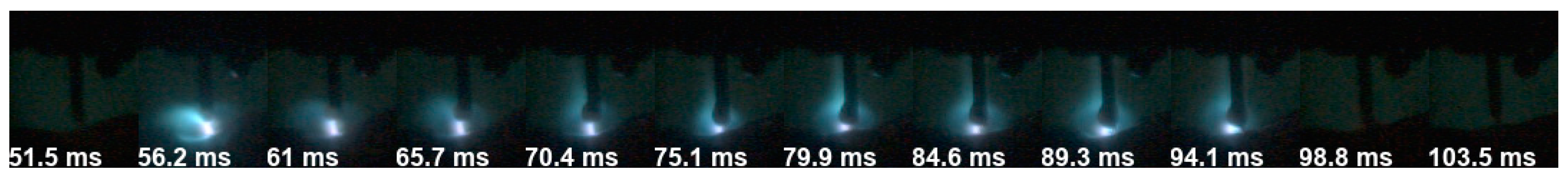
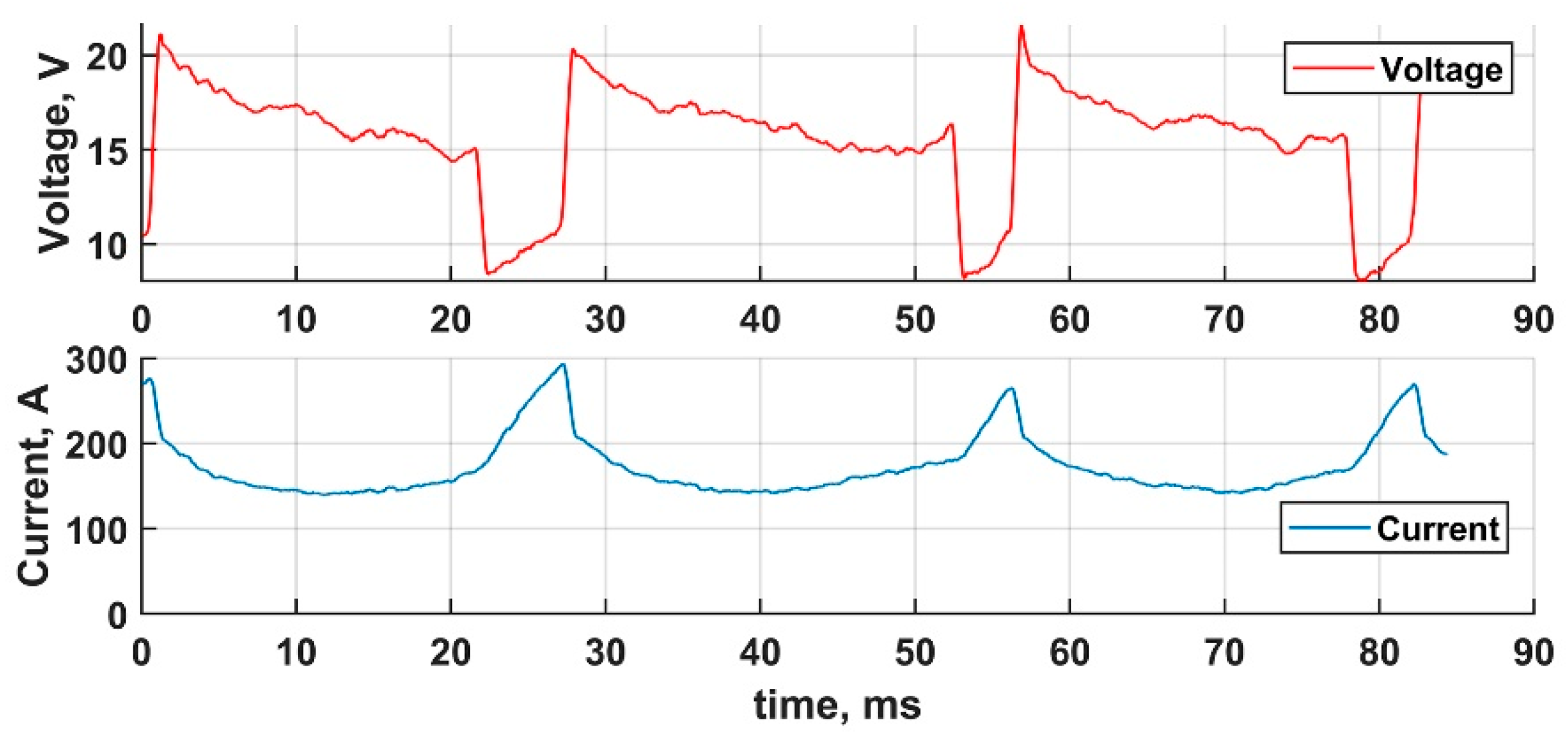
3.2. CSC
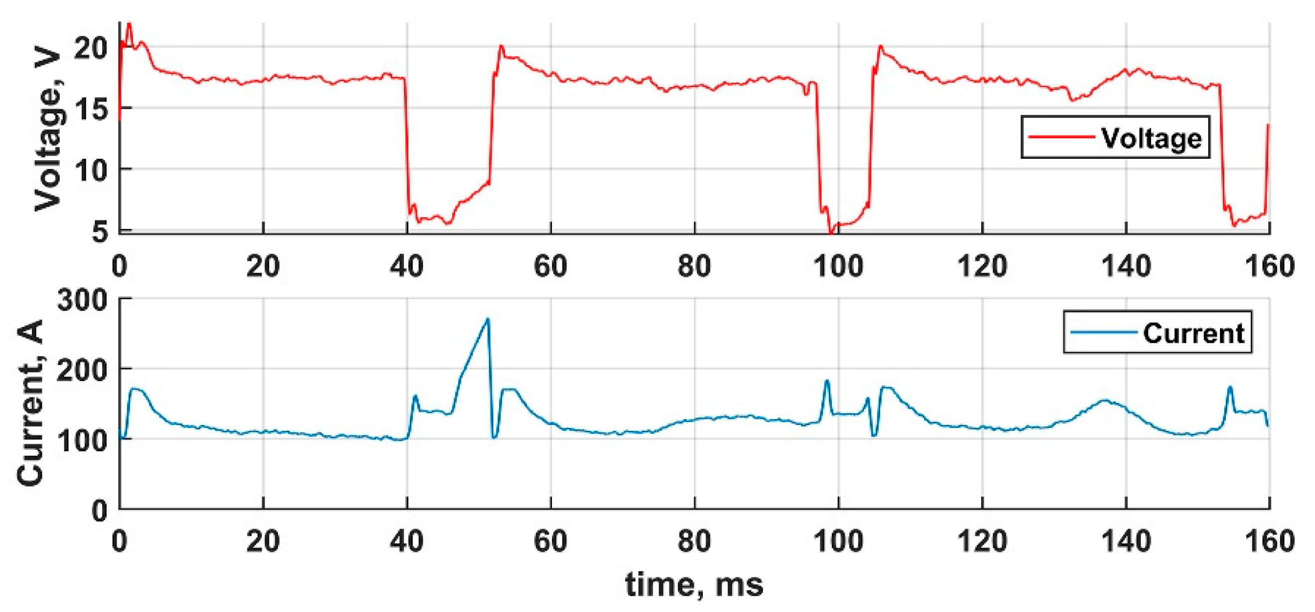
3.3. DCEN
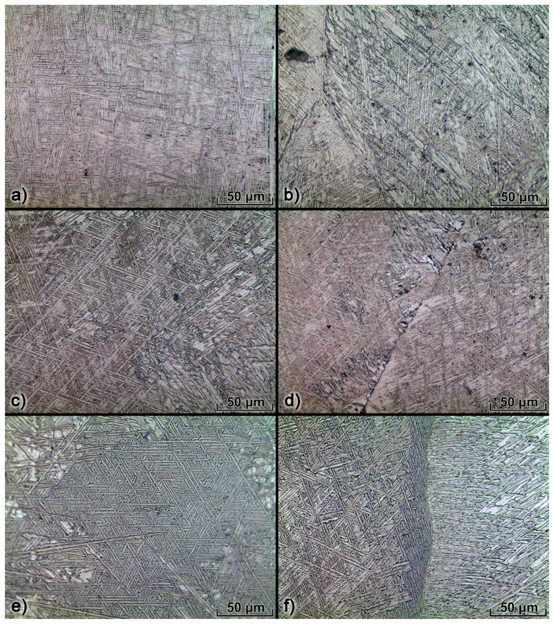
3.4. Microstructure
4. Conclusions
- During CMT, the burning arc at the ignition start misses the wire tip, which occurs almost in every cycle and can significantly affect the heat input distribution. Such a phenomenon can be explained by the cumulative effect of the low wire tip temperature and the refractory properties of Ti, which results in insufficient anode vaporization; the lack of anode vaporization develops in the diffusive arc burning mode until the wire tip is heated enough to produce the anode spot. The discovered effect tends to play a crucial role in arc burning stability during CMT.
- The effective wall width considerably differs between walls, printed using different transfer modes. The width efficiencies are 0.62, 0.76, and 0.56 for the CMT, CSC, and DCEN walls, respectively. The wall width efficiency is influenced by the wall waviness, which depends on the heat input distribution. Heat input distribution varies during GMAW due to arc wandering, and its effect is greater in the CMT process as a result of the extended arc length. The DCEN wall inconsistency is a consequence of the higher heat input into the anode, which in the case of DCEN is the wall. The relatively high CSC wall efficiency is the result of the low arc length and sufficient heat input, produced during the arc burning phase of the metal transfer cycle.
- There was no critical difference found in the printed walls microstructure, thus the metal transfer at the investigated intervals of the transfer parameters primarily influences the geometrical properties of the manufactured structures.
- Owing to its width efficiency and sufficient arc stability, the CSC transfer process was found to be the most suitable for thin-walled structure printing among the three studied metal transfer modes. The next study will be dedicated to further development of CSC metal transfer at higher process rates.
Supplementary Materials
Author Contributions
Funding
Data Availability Statement
Conflicts of Interest
References
- Wang, F.; Williams, S.; Colegrove, P.; Antonysamy, A.A. Microstructure and mechanical properties of wire and arc additive manufactured Ti-6Al-4V. Metall. Mater. Trans. A Phys. Metall. Mater. Sci. 2013, 44, 968–977. [Google Scholar] [CrossRef]
- Wu, B.; Pan, Z.; Ding, D.; Cuiuri, D.; Li, H. Effects of heat accumulation on microstructure and mechanical properties of Ti6Al4V alloy deposited by wire arc additive manufacturing. Addit. Manuf. 2018, 23, 151–160. [Google Scholar] [CrossRef]
- Zhang, X.; Martina, F.; Ding, J.; Wang, X.; Williams, S.W. Fracture toughness and fatigue crack growth rate properties in wire + arc additive manufactured Ti-6Al-4V. Fatigue Fract. Eng. Mater. Struct. 2017, 40, 790–803. [Google Scholar] [CrossRef]
- Wang, J.; Lin, X.; Wang, J.; Yang, H.; Zhou, Y.; Wang, C.; Li, Q.; Huang, W. Grain morphology evolution and texture characterization of wire and arc additive manufactured Ti-6Al-4V. J. Alloys Compd. 2018, 768, 97–113. [Google Scholar] [CrossRef]
- Wang, J.; Lin, X.; Li, J.; Hu, Y.; Zhou, Y.; Wang, C.; Li, Q.; Huang, W. Effects of deposition strategies on macro/microstructure and mechanical properties of wire and arc additive manufactured Ti–6Al–4V. Mater. Sci. Eng. A 2019, 754, 735–749. [Google Scholar] [CrossRef]
- Wu, B.; Pan, Z.; Chen, G.; Ding, D.; Yuan, L.; Cuiuri, D.; Li, H. Mitigation of thermal distortion in wire arc additively manufactured Ti6Al4V part using active interpass cooling. Sci. Technol. Weld. Join. 2019, 24, 484–494. [Google Scholar] [CrossRef]
- Xue, L.; Xiao, J.; Nie, Z.; Hao, F.; Chen, R.; Liu, C.; Yu, X.; Tan, C. Dynamic response of Ti-6.5Al–1Mo–1V–2Zr-0.1B alloy fabricated by wire arc additive manufacturing. Mater. Sci. Eng. A 2021, 800. [Google Scholar] [CrossRef]
- Zhou, Y.; Qin, G.; Li, L.; Lu, X.; Jing, R.; Xing, X.; Yang, Q. Formability, microstructure and mechanical properties of Ti-6Al-4V deposited by wire and arc additive manufacturing with different deposition paths. Mater. Sci. Eng. A 2020, 772. [Google Scholar] [CrossRef]
- Caballero, A.; Ding, J.; Bandari, Y.; Williams, S. Oxidation of Ti-6Al-4V during Wire and Arc Additive Manufacture. 3D Print. Addit. Manuf. 2019, 6, 91–98. [Google Scholar] [CrossRef]
- Wang, C.; Suder, W.; Ding, J.; Williams, S. The effect of wire size on high deposition rate wire and plasma arc additive manufacture of Ti-6Al-4V. J. Mater. Process. Technol. 2021, 288. [Google Scholar] [CrossRef]
- Zhang, X.; Syed, A.K.; Biswal, R.; Martina, F.; Ding, J.; Williams, S. High Cycle Fatigue and Fatigue Crack Growth Rate in Additive Manufactured Titanium Alloys. In Proceedings of the Lecture Notes in Mechanical Engineering; Springer: Berlin, Germany, 2020; pp. 31–42. [Google Scholar]
- Bermingham, M.J.; Nicastro, L.; Kent, D.; Chen, Y.; Dargusch, M.S. Optimising the mechanical properties of Ti-6Al-4V components produced by wire + arc additive manufacturing with post-process heat treatments. J. Alloys Compd. 2018, 753, 247–255. [Google Scholar] [CrossRef]
- Davis, A.E.; Kennedy, J.R.; Ding, J.; Prangnell, P.B. The effect of processing parameters on rapid-heating β recrystallization in inter-pass deformed Ti-6Al-4V wire-arc additive manufacturing. Mater. Charact. 2020, 163. [Google Scholar] [CrossRef]
- Ding, D.; Wu, B.; Pan, Z.; Qiu, Z.; Li, H. Wire arc additive manufacturing of Ti6AL4V using active interpass cooling. Mater. Manuf. Process. 2020, 35, 845–851. [Google Scholar] [CrossRef]
- Yang, Y.; Jin, X.; Liu, C.; Xiao, M.; Lu, J.; Fan, H.; Ma, S. Residual stress, mechanical properties, and grain morphology of Ti-6Al-4V alloy produced by ultrasonic impact treatment assisted wire and arc additive manufacturing. Metals 2018, 8, 934. [Google Scholar] [CrossRef]
- Benakis, M.; Costanzo, D.; Patran, A. Current mode effects on weld bead geometry and heat affected zone in pulsed wire arc additive manufacturing of Ti-6-4 and Inconel 718. J. Manuf. Process. 2020, 60, 61–74. [Google Scholar] [CrossRef]
- Knezović, N.; Garašić, I.; Jurić, I. Influence of the interlayer temperature on structure and properties of wire and arc additive manufactured duplex stainless steel product. Materials 2020, 13, 5795. [Google Scholar] [CrossRef] [PubMed]
- Gierth, M.; Henckell, P.; Ali, Y.; Scholl, J.; Bergmann, J.P. Wire Arc Additive Manufacturing (WAAM) of Aluminum Alloy AlMg5Mn with Energy-Reduced Gas Metal Arc Welding (GMAW). Materials 2020, 13, 2671. [Google Scholar] [CrossRef] [PubMed]
- Panchenko, O.; Kurushkin, D.; Mushnikov, I.; Khismatullin, A.; Popovich, A. A high-performance WAAM process for Al–Mg–Mn using controlled short-circuiting metal transfer at increased wire feed rate and increased travel speed. Mater. Des. 2020, 195. [Google Scholar] [CrossRef]
- Kou, S. Welding Metallurgy, 2nd ed.; John Wiley & Sons, Inc.: Hoboken, NJ, USA, 2003; ISBN 0-471-43491-4. [Google Scholar]
- Pickin, C.G.; Young, K. Evaluation of cold metal transfer (CMT) process for welding aluminium alloy. Sci. Technol. Weld. Join. 2006, 11, 583–585. [Google Scholar] [CrossRef]
- Eickhoff, S.T.; Eagar, T.W. Characterization of Spatter in Low-Current GMAW of Titanium Alloy Plate. Weld. J. 1990, 69, 382. [Google Scholar]
- Shinn, B.W.; Farson, D.F.; Denney, P.E. Laser stabilisation of arc cathode spots in titanium welding. Sci. Technol. Weld. Join. 2005, 10, 475–481. [Google Scholar] [CrossRef]
- Zhang, Y.M.; Li, P.J. Modified active control of metal transfer and pulsed GMAW of titanium. Weld. J. 2001, 80, 54. [Google Scholar]
- Otani, T. Titanium welding technology. Nippon Steel Tech. Rep. 2007, 95, 88–92. [Google Scholar]
- Choudhury, S.S.; Marya, S.K.; Amirthalingam, M. Improving arc stability during wire arc additive manufacturing of thin-walled titanium components. J. Manuf. Process. 2021, 66, 53–69. [Google Scholar] [CrossRef]
- Denney, P.E.; Shinn, B.W.; Fallara, P.M. Stabilization of Pulsed GMAW in Titanium Welds with Low-Power Lasers. In Proceedings of the ICALEO 2004—23rd International Congress on Applications of Laser and Electro-Optics, Congress Proceedings, San Francisco, CA, USA, 4–7 October 2004; Laser Institute of America: Orlando, FL, USA, 2004. [Google Scholar]
- Brandizzi, M.; Satriano, A.A.; Tricarico, L. CO2 Laser—MIG Hybrid Welding of Titanium Alloy. In Proceedings of the Advanced Materials Research; Trans Tech Publications: Stafa-Zurich, Switzerland, 2011; Volume 264–265, pp. 1270–1280. [Google Scholar]
- Li, C.; Muneharua, K.; Takao, S.; Kouji, H. Fiber laser-GMA hybrid welding of commercially pure titanium. Mater. Des. 2009, 30, 109–114. [Google Scholar] [CrossRef]
- Li, C.; Ding-Yong, H.; Fu, G.; Xiao-Yan, L.; Jian-Min, J. Effect of fiber laser-MIG hybrid process parameters on weld bead shape and tensile properties of commercially pure titanium. Mater. Manuf. Process. 2010, 25, 1309–1316. [Google Scholar] [CrossRef]
- Li, R.; Zhang, F.; Sun, T.; Liu, B.; Chen, S.; Tian, Y. Investigation of strengthening mechanism of commercially pure titanium joints fabricated by autogenously laser beam welding and laser-MIG hybrid welding processes. Int. J. Adv. Manuf. Technol. 2019, 101, 377–389. [Google Scholar] [CrossRef]
- Spina, R.; Sorgente, D.; Palumbo, G.; Scintilla, L.D.; Brandizzi, M.; Satriano, A.A.; Tricarico, L. T-Joints of Ti Alloys with Hybrid Laser-MIG Welding: Macro-Graphic and Micro-Hardness Analyses. In Proceedings of the High Power Laser Materials Processing: Lasers, Beam Delivery, Diagnostics, and Applications, San Francisco, CA, USA, 10–12 February 2015; Volume 8239, p. 82390C. [Google Scholar]
- Zhang, M.; Yang, D.; Chen, G. Study on Microstructure and Properties of Laser-MIG Hybrid Welding Joints for Ti-70 Alloy. In Proceedings of the Applied Mechanics and Materials, San Francisco, CA, USA, 5–7 February 2013; Trans Tech Publications: Stafa-Zurich, Switzerland, 2013; Volume 607, pp. 128–132. [Google Scholar]
- Sun, Z.; Lv, Y.; Xu, B.; Liu, Y.; Lin, J.; Wang, K. Investigation of droplet transfer behaviours in cold metal transfer (CMT) process on welding Ti-6Al-4V alloy. Int. J. Adv. Manuf. Technol. 2015, 80, 2007–2014. [Google Scholar] [CrossRef]
- Elmer, J.W.; Gibbs, G. The effect of atmosphere on the composition of wire arc additive manufactured metal components. Sci. Technol. Weld. Join. 2019, 24, 367–374. [Google Scholar] [CrossRef]
- Vázquez, L.; Rodríguez, N.; Rodríguez, I.; Alberdi, E.; Álvarez, P. Influence of interpass cooling conditions on microstructure and tensile properties of Ti-6Al-4V parts manufactured by WAAM. Weld. World 2020, 64, 1377–1388. [Google Scholar] [CrossRef]
- Pardal, G.; Martina, F.; Williams, S. Laser stabilization of GMAW additive manufacturing of Ti-6Al-4V components. J. Mater. Process. Technol. 2019, 272, 1–8. [Google Scholar] [CrossRef]
- Miller, H.C.; Phenomena, A. Handbook of Vacuum arc Science and Technology: Fundamentals and Applications; Boxman, R.L., Sanders, D.M., Martin, P.J., Eds.; William Andrew Publishing: Norwich, NY, USA, 1996; pp. 308–364. ISBN 9780815513759. [Google Scholar]
- Hantzsche, E. Mysteries of the arc cathode spot: A retrospective glance. IEEE Trans. Plasma Sci. 2003, 31, 799–808. [Google Scholar] [CrossRef]
- Kurushkin, D. High-Speed Videos of CMT, CSC and DCEN Metal Transfer Modes during WAAM of Ti-Alloy; Mendeley Data; V1. 2021. Available online: http://dx.doi.org/10.17632/8ck8h6z3wp.1 (accessed on 13 April 2021).
- Chen, R.; Tan, C.; Yu, Y.; Zhang, M.; Yu, X.; Liu, C.; Ye, W.; Hui, S.; Jiang, Y. Modification of α-phase of wire + arc additive manufactured Ti-6Al-4 V alloy with boron addition. Mater. Charact. 2020, 169. [Google Scholar] [CrossRef]
- Biswal, R.; Zhang, X.; Syed, A.K.; Awd, M.; Ding, J.; Walther, F.; Williams, S. Criticality of porosity defects on the fatigue performance of wire + arc additive manufactured titanium alloy. Int. J. Fatigue 2019, 122, 208–217. [Google Scholar] [CrossRef]
- Bambach, M.; Sizova, I.; Sydow, B.; Hemes, S.; Meiners, F. Hybrid manufacturing of components from Ti-6Al-4V by metal forming and wire-arc additive manufacturing. J. Mater. Process. Technol. 2020, 282. [Google Scholar] [CrossRef]
- Ho, A.; Zhao, H.; Fellowes, J.W.; Martina, F.; Davis, A.E.; Prangnell, P.B. On the origin of microstructural banding in Ti-6Al4V wire-arc based high deposition rate additive manufacturing. Acta Mater. 2019, 166, 306–323. [Google Scholar] [CrossRef]


| Metal Transfer Mode | Average Current, A | Average Voltage, V |
|---|---|---|
| CMT | 63 | 11.3 |
| CSC | 127 | 15.7 |
| DCEN | 174 | 15.6 |
Publisher’s Note: MDPI stays neutral with regard to jurisdictional claims in published maps and institutional affiliations. |
© 2021 by the authors. Licensee MDPI, Basel, Switzerland. This article is an open access article distributed under the terms and conditions of the Creative Commons Attribution (CC BY) license (https://creativecommons.org/licenses/by/4.0/).
Share and Cite
Panchenko, O.; Kurushkin, D.; Isupov, F.; Naumov, A.; Kladov, I.; Surenkova, M. Gas Metal Arc Welding Modes in Wire Arc Additive Manufacturing of Ti-6Al-4V. Materials 2021, 14, 2457. https://doi.org/10.3390/ma14092457
Panchenko O, Kurushkin D, Isupov F, Naumov A, Kladov I, Surenkova M. Gas Metal Arc Welding Modes in Wire Arc Additive Manufacturing of Ti-6Al-4V. Materials. 2021; 14(9):2457. https://doi.org/10.3390/ma14092457
Chicago/Turabian StylePanchenko, Oleg, Dmitry Kurushkin, Fedor Isupov, Anton Naumov, Ivan Kladov, and Margarita Surenkova. 2021. "Gas Metal Arc Welding Modes in Wire Arc Additive Manufacturing of Ti-6Al-4V" Materials 14, no. 9: 2457. https://doi.org/10.3390/ma14092457
APA StylePanchenko, O., Kurushkin, D., Isupov, F., Naumov, A., Kladov, I., & Surenkova, M. (2021). Gas Metal Arc Welding Modes in Wire Arc Additive Manufacturing of Ti-6Al-4V. Materials, 14(9), 2457. https://doi.org/10.3390/ma14092457