2. Materials and Methods
The ceramic powders proposed in this study α-Al2O3 alumina, designation TM-DAR, from Tamei Chemicals (Tokyo, Japan), and ZrO2 stabilised with 3% mol Y2O3 from Tosoh Co. (Tokyo, Japan), designation TZ-PX-245. According to the manufacturer’s data, Al2O3 powder had an average particle size of d50 = 100 nm, while TZ3 powder’s average particle size of d50 = 40 nm. The powders characterized by a purity of 99.99%. The choice of said Al2O3 and TZ3 powders was dictated by a large number of published studies on colloidal formation using these powders. The results obtained can thus be compared with literature data. Additionally, the selection of the ceramic powders was guided by the size of the starting powders and their high purity (99.99%).
A composition of liquefiers (diammonium hydrogen citrate (DAC) and citric acid (CA)) was used to properly liquefy ceramic casting slips and obtain the required rheological properties. A 10% polyvinyl alcohol (PVA) solution was proposed as a binder. The amounts of liquefiers and binder used in the work were selected experimentally based on previous research [
20,
26,
27].
In this study, four series of samples with different TZ3 content were prepared: Series I containing 100 vol.% Al
2O
3 (0 vol.% ZrO
2), Series II containing 5 vol.% ZrO
2, Series III containing 10 vol.% ZrO
2, and Series IV containing 100 vol.% ZrO
2 relative to the total solid phase content. Each of the prepared aqueous casting slips had a solid phase content of 50 vol.%. Pre-homogenisation of the casting slip in a planetary mill at 5 s
−1 for 1 h resulted in uniform dispersion of TZ3 powder in the composites produced. The compositions of the slips used to produce each series are shown in
Table 1. The centrifugal slip casting method proposed in this study to obtain ceramic shapes was based on a commonly accepted procedure proposed in earlier studies and presented in previous work [
20].
Figure 1 shows the device used to produce samples by centrifugal slip casting along with a photo of the manufactured sample.
A number of research techniques have been used in the study to characterize the Al2O3 and TZ3 powders employed, the slurries proposed in the centrifugal slip casting method and the composite samples after the sintering process.
Rheological tests of the ceramic casting slips were carried out using a Kinexus Pro rheometer (Malvern Panalytical, Malvern, UK) in a plate-to-plate system. The measuring gap width was 0.5 mm in each case. In order to protect each sample from drying out during measurement, poly(dimethylsiloxane) was sprinkled at the edges of the measurement frame and did not mix with the ceramic suspensions. Dynamic viscosity as well as shear stress as a function of shear rate were measured in two stages. In the first stage, the measurements were carried out with an increasing shear rate from 0.1 to 100 s−1, while in the second stage with a decreasing shear rate from 100 to 0.1 s−1. Oscillatory measurements were also carried out in two stages. The first stage—the amplitude scan—was carried out at a constant frequency of 1 Hz, determining the modulus G′ (conservative) and modulus G′′ (loss) as a function of increasing shear strain in the range from 0.01 to 100%. This determined the range of the Linear Viscoelastic Region—LVER. The second stage was conducted at constant LVER deformation (determined from the first measurement) with a variable frequency which decreased from 10 to 0.1 Hz during the measurement.
The primary characterization of the shapes after cutting involved measuring their density as well as volumetric and linear shrinkage. The relative density was determined using the hydrostatic weighing method according to the ISO 18754:2013 (EN) standard [
28]. For this purpose, the sintered shapes were cut into smaller fragments measuring 0.5 cm in height. The weight of the samples prepared in this way was determined, following which the samples were boiled for 1 h in distilled water. Afterwards, the samples were weighed while immersed in water. After removing excess water from the surface, the soaked samples were weighed again. To determine the level of sinter compaction, relative density was calculated using the density of the powders designated using a helium pycnometer (AccuPyc 1340 II by Micrometrics, Norcross, GA, USA) or using the density of the composite calculated according to the rule of mixtures.
Microscopic observations were carried out to determine the morphology of the starting powders and the microstructure of the produced shapes after the sintering process. Both cross-sectional and fracture observations were performed. Microstructure investigations were carried out to determine how the ZrO
2 particles were distributed in the composites. In addition, microscopic images allowed the determination of grain growth resulting from the sintering process. The experiments were performed using a JSM-6610 scanning electron microscope (JEOL, Tokyo, Japan). In addition, to characterize the structure of the phase boundary between alumina and zirconium oxide, observations were made using a STEM S 5000 microscope (Hitachi, Tokyo, Japan) on thin specimens using the bright field technique. Samples were prepared by ion beam thinning (Hitachi FIB/SEM NB5000 microscope) using a standard sample cutting procedure as described in the work by Andrzejczuk [
29].
Surface microanalysis of the chemical composition was performed using an X-Max type electro-dispersive X-ray spectrometer (EDS, Oxford, UK) to determine the elemental distribution in the fabricated shapes. Prior to the observations, the samples were sputtered with a thin layer of carbon.
Structural X-Ray Diffraction (XRD) was performed to analyse the phase composition of the starting powders, the raw shapes and materials after sintering. The analyses were performed using a Miniflex2 diffractometer (Rigaku Corporation, Tokyo, Japan) equipped with a copper lamp. The studies were carried out in the angular range of 20–100°, with a step of 2θ = 0.02° at a counting time of 1 s. The ICDD PDF-4 + 2020 X-ray standard database using MDI JADE 7 software (MaterialsData, CA, USA) was used to interpret the results for a qualitative analysis of the diffractograms.
In this study, stereological methods were proposed to quantitatively describe Al
2O
3 and ZrO
2 particles in the shapes after sintering. The average size of Al
2O
3 and ZrO
2 particles and the effect of ZrO
2 content on Al
2O
3 grain growth during the sintering process were determined. Afterwards, the following shape parameters were verified: elongation (α = d
max/d
2), curvature of grain boundary (R = p/(π d
2)), and convexity (W = p/p
c) (where d
max—maximum diameter of void projection [μm], d
2—diameter of a circle of the same surface as the surface of the analysed grain [μm], p—perimeter of void [μm], p
c—Cauchy perimeter [μm]) [
30,
31]. All calculations were performed using the “MicroMeter” program [
30,
31] on the basis of information derived from analysing photographs of randomly selected fractures. The particle count for each series of samples was a minimum of 1200 elements. Quantitative analysis was conducted on binary images. The binary images were obtained by binarisation of multishade images.
Hardness was measured using the Vikers method to determine the basic mechanical properties of the ceramic and composite shapes after sintering [
32]. Vickers hardness was determined using a DURA SCAN 70 microhardness tester (Struers Inc., Cleveland, OH, USA) and at least nine impressions were made for each specimen at a loading force of 10 kG (98.1 N). After the target force was reached, the load was maintained for 10 s.
The environmental impacts associated with the production of Al
2O
3/ZrO
2 sinters were evaluated using the life cycle assessment (LCA) method. The analysis was based on the requirements of ISO 14044 [
24] in a scope encompassing sourcing and processing of raw materials—module A1—and product manufacturing—A3, according to the guidelines of EN 15804 [
25]. Mass allocation was used in the calculations. All impacts related to the manufacturing of components ZrO
2, Al
2O
3, DAC, CA, PVA and distilled water were included in module A1. The impacts associated with the generation and consumption of electricity to power the equipment proposed in the fabrication of Al
2O
3/ZrO
2 sinter under laboratory conditions were included in module A3. Electricity consumption was determined based on operating time and manufacturers’ information on equipment power consumption. Waste volume was estimated at 1.5% of the initial mass loss after the deaeration process. The determined environmental impacts were expressed per piece of Al
2O
3/ZrO
2 sinter, with the mass resulting from the formulation. The inventory data (LCI) and environmental indicators used for LCA calculations were derived from the Ecoinvent v. 3.7 database of Environmental Product Declarations (EPD) and the Kobize 2020 report [
33].
3. Results and Discussion
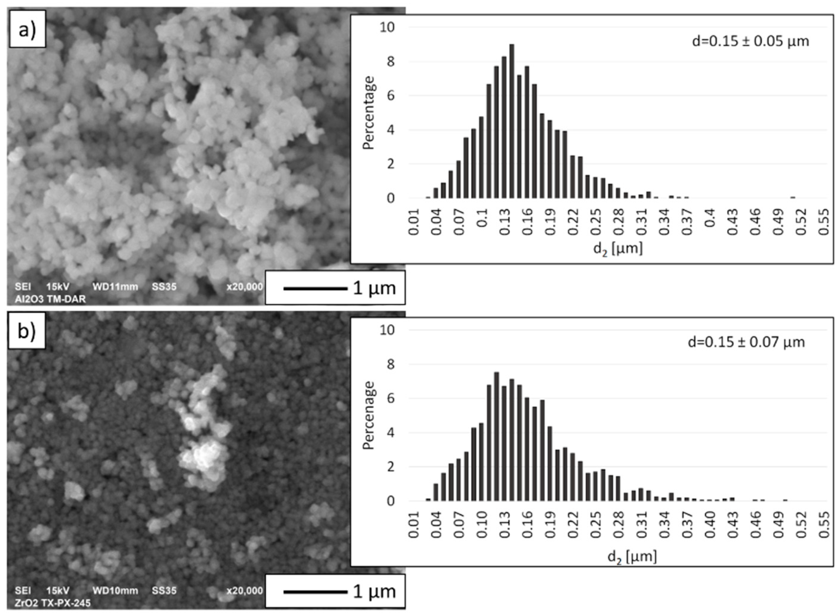
Figure 2 shows scanning electron microscope micrographs of the ceramic powders used in this work along with the particle size distribution of the powders determined from a computer analysis of the SEM images. The characteristics of the basic parameters of the powders are shown in
Table 2. Based on SEM images and histograms showing the size distribution of the initial powders it was found that the actual size of both powders corresponds to the size stated by the manufacturer. Based on the SEM micrographs (
Figure 2), it was observed that both Al
2O
3 and TZ3 powders featured a regular shape. Furthermore, it was observed that the powders used in the experiment tended to form agglomerates. The histogram analysis showed that the Al
2O
3 powder has a unimodal distribution ranging from 0.03 µm to 0.51 µm. A unimodal particle size distribution was also obtained for TZ3 powder. From the values obtained, TZ3 particles were found to range from 0.03 µm to 0.50 µm.
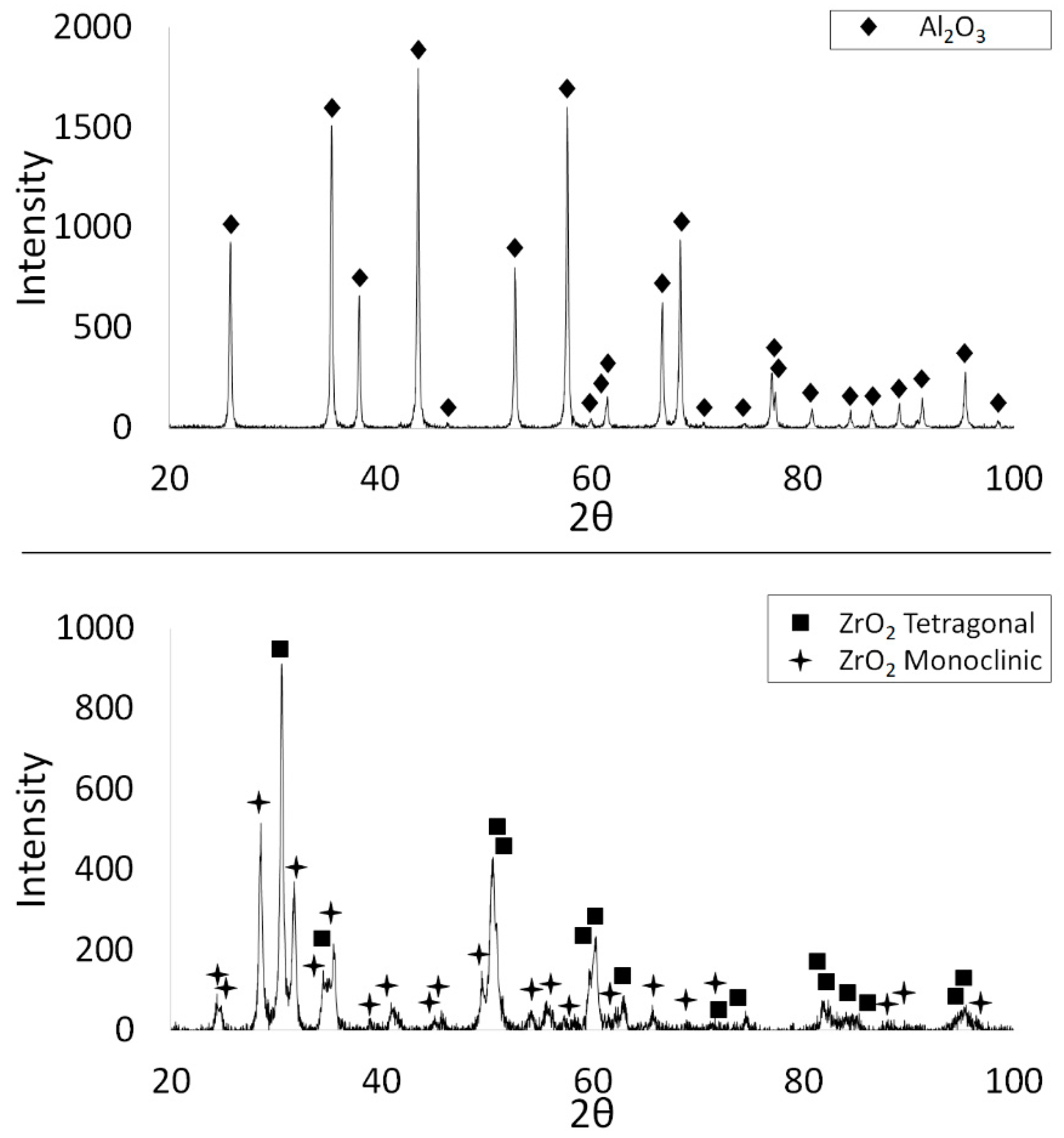
XRD phase analysis was performed to determine the phase composition of the starting powders.
Figure 3 shows the obtained X-ray diffractograms of the studied powders. The measurements showed that the ZrO
2 powder exhibited a two-phase structure: tetragonal and monoclinic. Based on the results, the tetragonal phase accounted for 45.1%, while the monoclinic phase for 54.9%. XRD examinations revealed that the Al
2O
3 powder has a corundum structure.
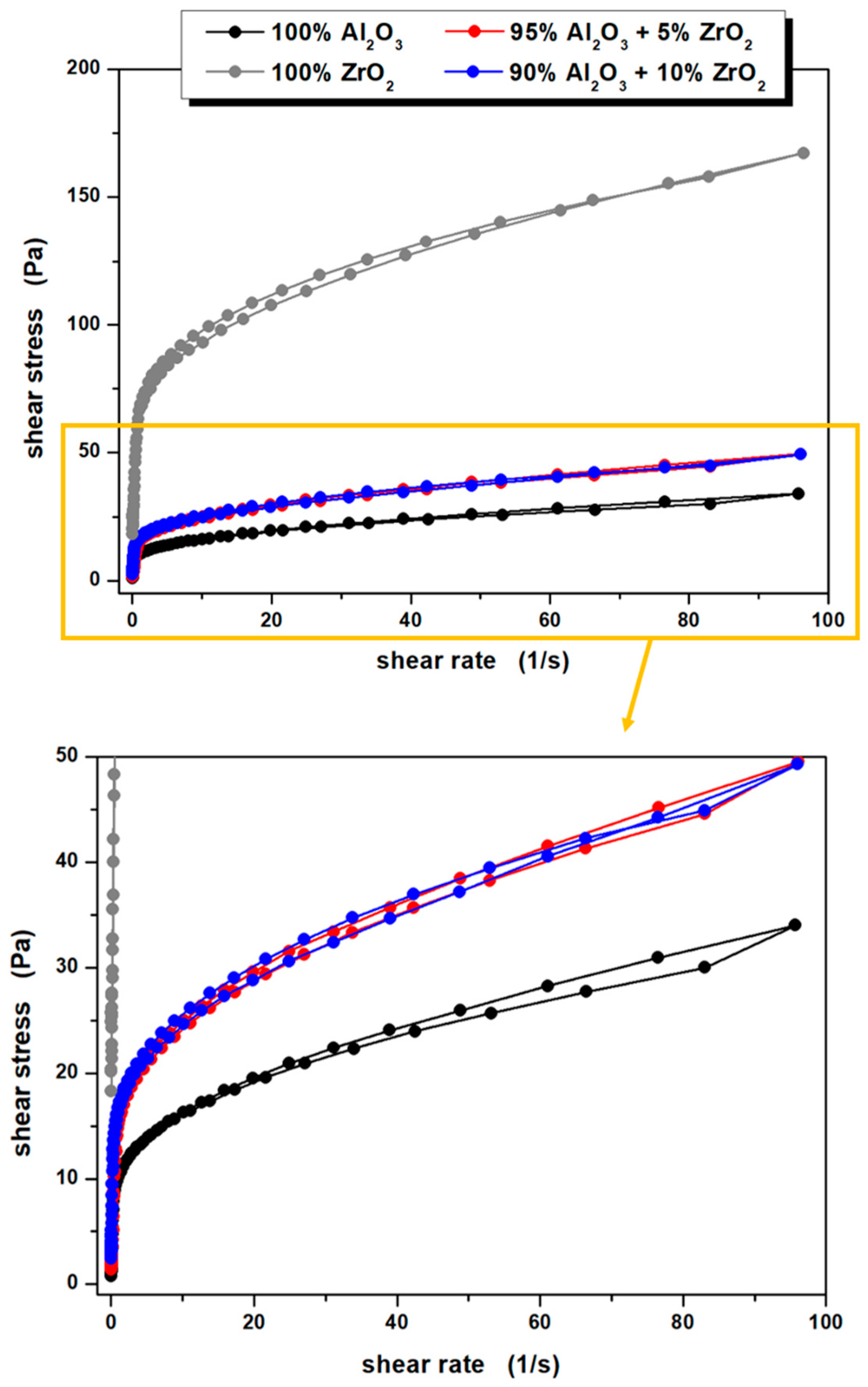
The rheological properties of the ceramic casting slips, measurements of viscosity and shear stress as a function of shear rate were performed. The data shown in
Figure 4 indicates that all of the prepared ceramic suspensions exhibit non-Newtonian flow characteristics. For the suspension whose solid phase is based solely on TZ3 powder, shear thinning is evident throughout the shear rate range studied, which correlates well with literature data [
34]. The other suspensions i.e., containing only Al
2O
3 or a mixture of Al
2O
3 with TZ3 also exhibit shear thinning in almost the entire range studied. It is worth noting, however, that in these suspensions a slight increase in fluid viscosity (slight shear thickening) was observed in the low shear rate range, specifically between 0.1 and 0.5 s
−1. The increase in viscosity of these suspensions was 6.4, 1.2 and 1.7 Pa∙s for 100% Al
2O
3, 95% Al
2O
3 + 5% ZrO
2 and 90% Al
2O
3 + 10% ZrO
2 series, respectively, and is most likely associated with the enhancement of hydrodynamic attractive forces causing the formation of small hydroclasts of powder particles in the suspension [
35]. It is worth noting that the shear thickening phenomenon in aqueous Al
2O
3 suspensions subsequently used to form ceramic materials has already been reported e.g., by Montanaro et al. [
36]. Moreover, Mahbubula et al. observed a similar phenomenon in the aqueous/Al
2O
3 system even for a very small content of ceramic powder [
37].
When analysing the results obtained, it is also worth noting that the initial viscosity of the prepared ceramic suspensions is quite high. Moreover, it increases with higher ZrO
2 content in the slurry while maintaining the same volume fraction of the solid phase. Similar observations can be found in the literature [
38,
39].
The initial viscosities of the prepared suspensions are 100, 104, 346 and 788 Pa∙s for 100% Al
2O
3, 95% Al
2O
3 + 5% ZrO
2, 90% Al
2O
3 + 10% ZrO
2 and 100% ZrO
2 systems, respectively. Taking into account the relatively high compaction of solid phase particles and, consequently, a small average surface to surface separation distance between particles (SDP), which, according to Isobe et al. [
40], may be estimated at about 10 nm, a large accumulation of various types of interactions occurs in the analysed systems, e.g., Van der Waals interactions, dispersion interactions, electrostatic interactions or numerous hydrogen bonds. Moreover, due to the continuous Brownian motion, collisions between powder particles will occur, or these motions will cause a decrease in the distance between some particles, resulting in an increase in repulsive interactions. All this contributes to the relatively high initial viscosity of all the prepared systems. The application of small shear forces causes some of the hydrogen bonds to break, and orientates the suspension components along flow lines. This, of course, leads to a rapid reduction in dynamic viscosity, which is numerically presented in
Table 3. It is worth noting that the morphologies of both the Al
2O
3 and ZrO
2 powders used in the study are very similar, therefore the results obtained, and more specifically the significant differences in viscosity (especially in the low shear rate range) between the suspensions may indicate a completely different nature of the interaction of Al
2O
3 and ZrO
2 powders with water molecules and other fluid components.
Formation was observed of small hydroclastic powder particles at low shear rates (between 0.1 and 0.5 s−1), as well as the rather high initial viscosity of the prepared ceramic suspensions, should not have any adverse effects at the later stages in the formation of a tube-shaped product. The centrifugal slip-casting method adopted by the authors as a method of forming ceramic materials generates significantly higher stress values acting on the suspensions. The results of rheological tests carried out show unequivocally that in the high stress values range (high shear rates) all the suspensions undergo shear thinning, and their viscosity is very low. This is extremely beneficial when forming materials by centrifugal casting using gypsum moulds. Furthermore, differences in dynamic viscosity depending on the composition of the ceramic slurry are much less noticeable than is the case in the low shear rate range.
Based on the obtained flow curves of the prepared ceramic suspensions (
Figure 5), it can be additionally stated that they all exhibit weak thixotropic or antithixotropic properties, as evidenced by the occurrence of small hysteresis loops. At this point it is also worth pointing out the difference in the recorded properties depending on the slip composition: for the 100% Al
2O
3 and 95% Al
2O
3 + 5% ZrO
2 systems, slight thixotropy was recorded, while in the case of 90% Al
2O
3 + 10% ZrO
2 and 100% ZrO
2—antithixotropy was noted, which may also indicate a completely different nature of interactions of the applied ceramic powders with water molecules and other components of the suspensions. Interestingly, Pietrzak et al. [
41] in their studies using the same ceramic powders in aqueous systems, observed only thixotropic properties, but their systems were also doped with a large amount (ca. 4 wt.%) of monomers due to the formation method they chose—gelcasting. Moreover, it should be pointed out that thixotropic properties of aqueous ceramic suspensions may also be displayed when other modifiers are proposed, e.g., 6-O-acryloyl-d-galactose described in the work of Wiecinska et al. [
42], or metallic additives as reported earlier [
22].
Results of the pieces’ density and shrinkage are presented in
Table 4. Open porosity and water absorption values were not taken into account because all the ceramic pieces obtained had open porosity close to zero and therefore did not exhibit any water absorption. The open porosity value determined by the hydrostatic method mainly resulted from the roughness of the material and not from the presence of pores, which did not occur in the studied pieces. From the results obtained, it can be concluded that the samples containing 100 vol.% Al
2O
3 (Series I) and 100 vol.% ZrO
2 (Series IV) showed a very high density of 99.9%. Slightly lower densities were found in Series III composites with 10 vol.% ZrO
2. On the other hand, a lower density of 98.5% was obtained for Series II pieces—5 vol.% ZrO
2.
The physical properties measurements show that the average linear shrinkage for Series I, II, III was about 13%, while the volumetric shrinkage was determined to be 35%. For series IV pieces—100 vol.% ZrO2, the linear and volumetric shrinkage was higher at 18% and 43% respectively. The lower shrinkage values are most likely the result of good compaction of the samples in their raw state. On the other hand, the higher shrinkage values for Series IV-100 vol.% may be due to the greater distances between ZrO2 grains in the shapes, which resulted in higher shrinkage and lower compaction during the sintering process.
Figure 6 shows selected cross-sections of the shapes made using the CSC method. The grey areas in the micrographs correspond to Al
2O
3, while the bright areas are ZrO
2. Based on the observations, it was found that all the produced tubes have the same wall width regardless of the ZrO
2 content. This is because each of the casting slips used to produce the individual series had the same solid phase content of 50% by volume. Microscopic observations revealed no visible pores, cracks or other discontinuities in the structure. Moreover, microstructural observations of the obtained composites’ cross sections (Series II and Series III) revealed that they exhibit a uniform distribution of ZrO
2 in the Al
2O
3 matrix. Similar conclusions were presented in a paper by Al-Amin et al. on a review of research into methods of forming ZTA nanocomposites [
43]. According to Al-Amin et al., homogenisation of the slurry in a planetary mill makes it possible to obtain homogeneously dispersed ZrO
2 powder in the casting slip was used to produce samples [
43].
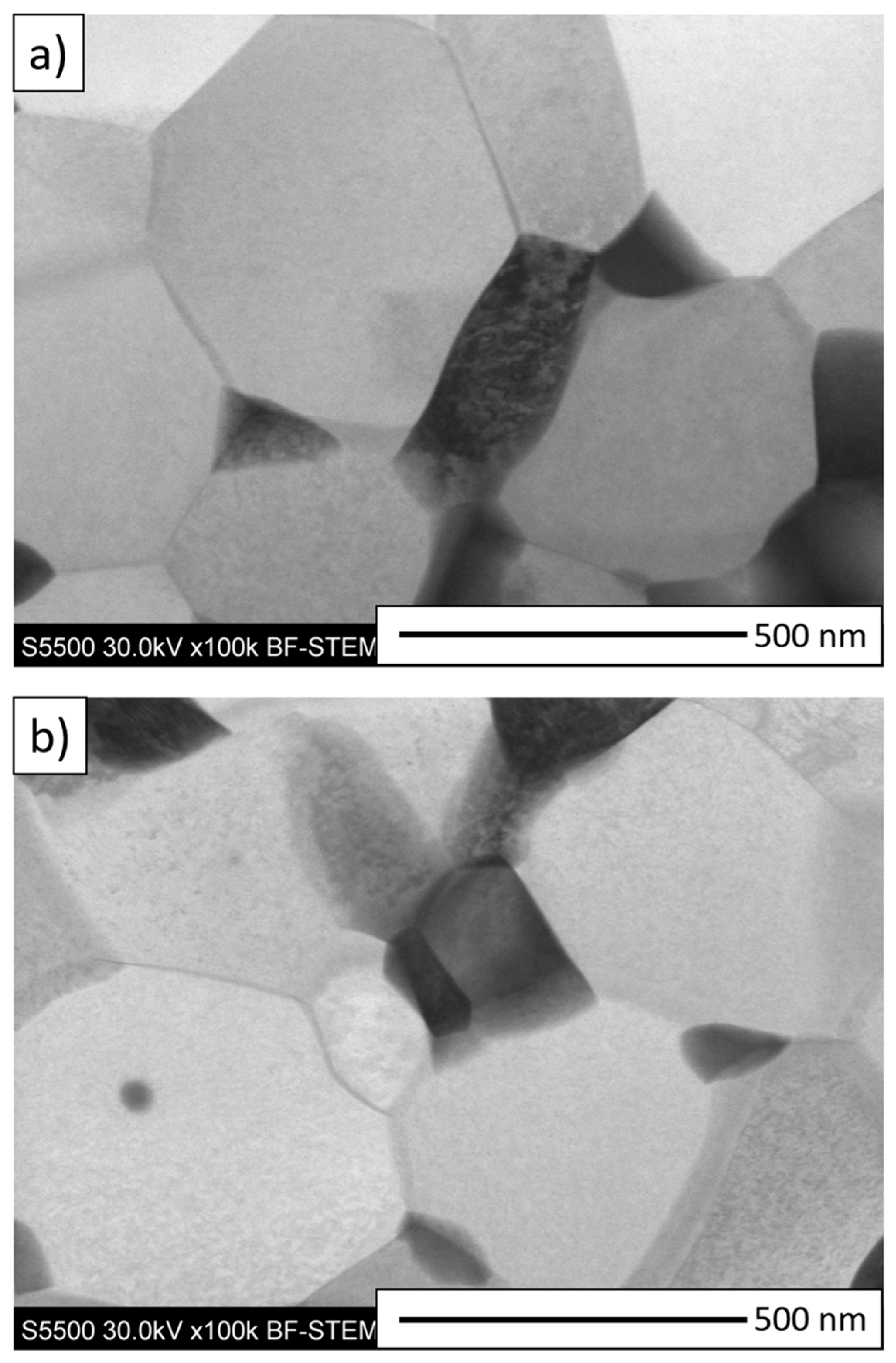
Additionally, to determine the phase boundary structure between ZrO
2 and Al
2O
3 for the composite samples from Series II—5 vol.% ZrO
2 and Series III—10 vol.% ZrO
2, thin film STEM observations were carried out. The obtained STEM micrographs are shown in
Figure 7. The bright areas in
Figure 7 correspond to Al
2O
3, while the dark areas are ZrO
2. The STEM observations confirmed the absence of delamination at the zirconium dioxide/alumina phase boundary in both series studied. In addition, the STEM micrographs obtained did not reveal any delamination, microcracks or other defects between the grain boundaries of the produced shapes. The obtained micrographs confirmed good bonding at the Al
2O
3/ZrO
2 phase boundaries and a high degree of densification of the composites produced by centrifugal slip casting.
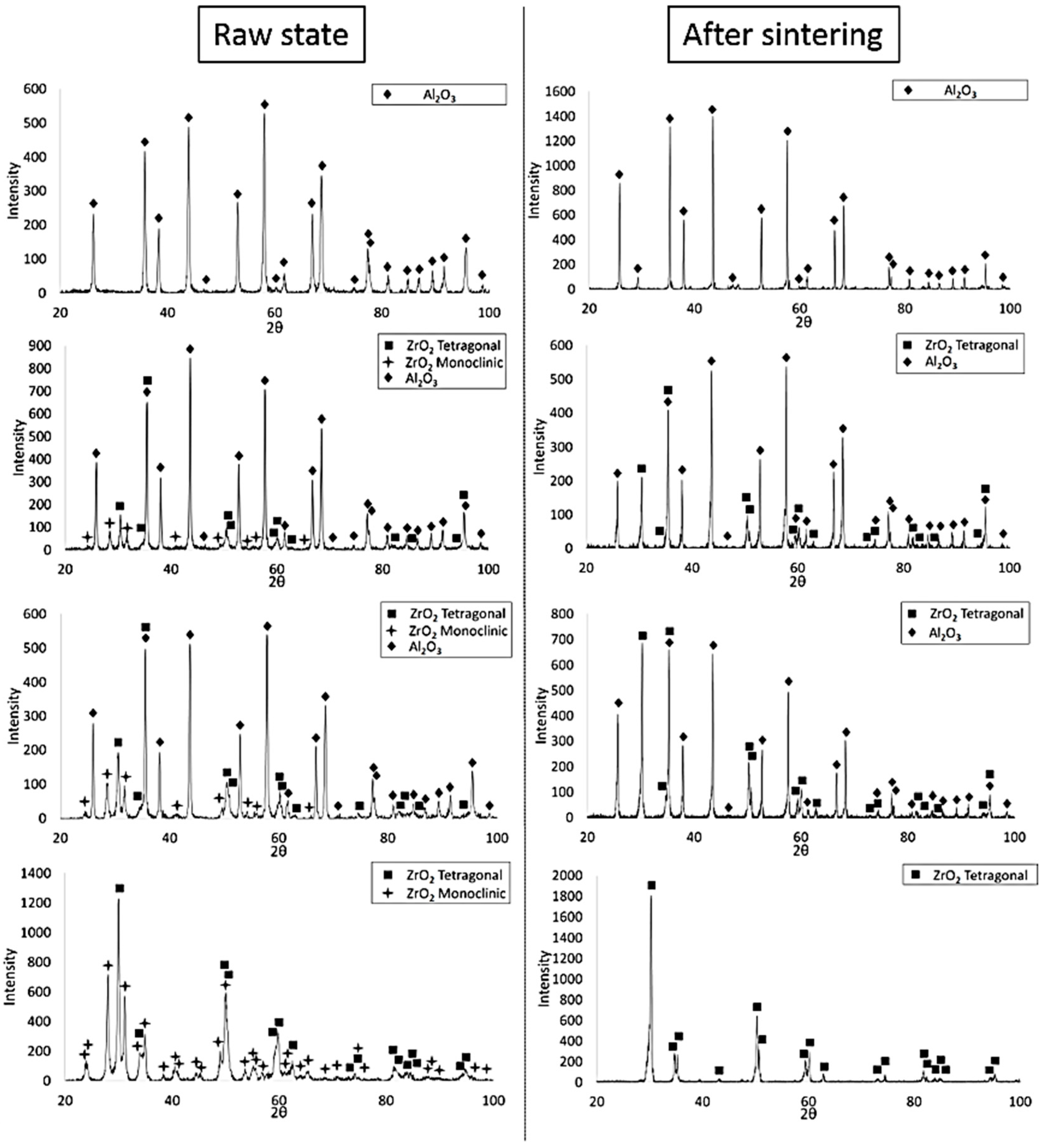
In the next step, the phase composition of the shapes before and after sintering was analysed. The obtained diffractograms are shown in
Figure 8. Phase analysis by X-ray diffraction showed that before sintering, the ZrO
2-bearing shapes of Series II, III and IV were characterised by the presence of the ZrO
2 tetragonal phase (spatial group O
4h15:P4
2/nmc) and the ZrO
2 monoclinic phase (spatial group O
2h5:P2
1/c) and Al
2O
3 (spatial group R-3c). The results obtained showed that after sintering, the ZrO
2-containing shapes were only characterised by the presence of the tetragonal ZrO
2 phase (spatial group O
4h15:P4
2/nmc). The diffraction line profiles of the ZrO
2-containing shapes after sintering differ in peak intensity. These differences are due to the change in ZrO
2 content in the individual shapes. As the ZrO
2 content in the samples increases, the intensity of the individual reflections corresponding to the tetragonal phase of ZrO
2 is higher. Furthermore, it was found that no peaks corresponding to the yttrium phase were found in the composition of the samples regardless of the series studied.
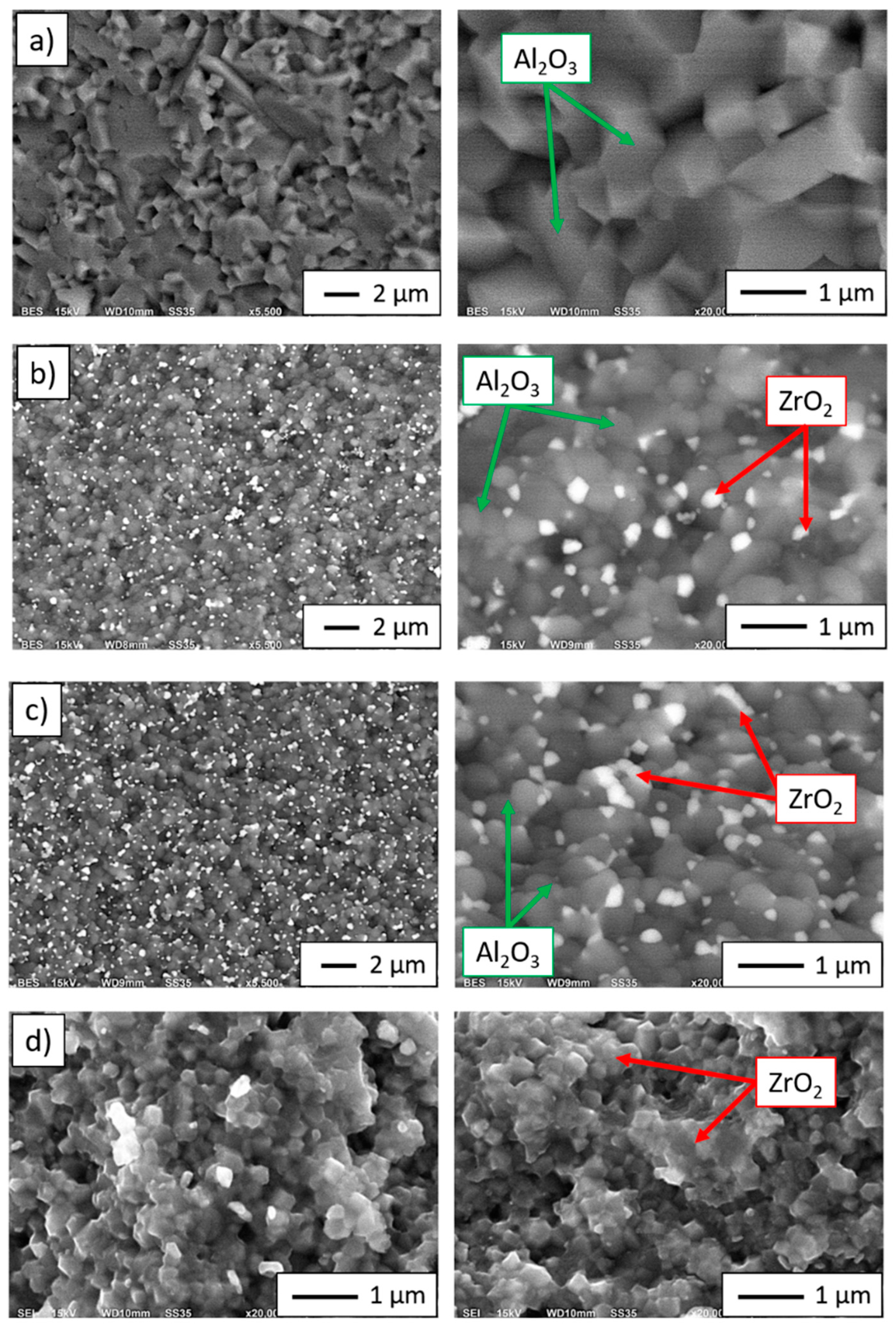
The SEM images (in backscattered electron—BSE mode) shown in
Figure 9a–d show characteristic areas of sintering with different ZrO
2 contents. In BSE mode, the zirconium dioxide phase is shown as light grey areas, while alumina is shown as dark grey areas. The observations were carried out at fracture sites. SEM studies revealed that the ZrO
2 particles are uniformly distributed in the alumina matrix, and no areas were observed that are second-phase over-enriched or depleted. Microstructural analysis confirmed that the zirconium particles do not form agglomerates in the alumina matrix for Series II and Series III. Fractography analysis of the samples revealed that the bonds between Al
2O
3 and ZrO
2 phases are the weakest points of the composite. Observation of cracks between them allows to conclude that debonding of the zirconia particles and the alumina matrix is main fracture mechanism of investigated composite. The occurrence of pulled out ZrO
2 particles in the form of craters in the matrix has been revealed. The presence of the pulled out particles confirms weak adhesion of metal particles with the matrix. Fracture observation allowed to conclude that the composites are characterized by the intergranular dynamic fracture mechanism. In SEM images (
Figure 9a–d) boundaries of all grains of the ceramic phases are visible what confirms the intergranular fracturing.
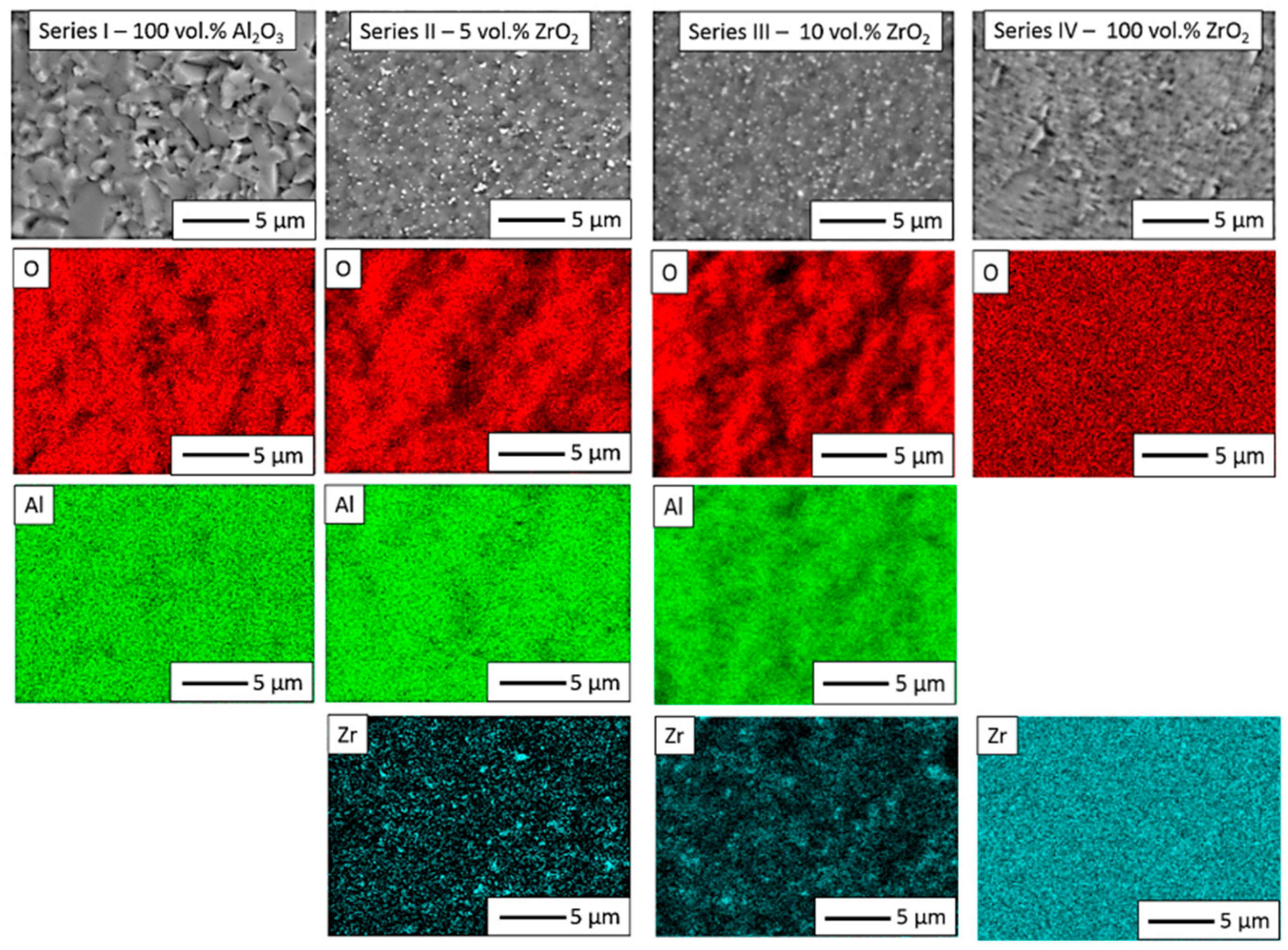
In the next step, Energy-dispersive X-ray spectroscopy (JEOL Ltd., Tokyo, Japan) was performed to obtain elemental distribution maps of the studied samples. The maps obtained are shown in
Figure 10. In Series I, only aluminium and oxygen were found. In Series II and Series III, the chemical element distribution maps showed a uniform distribution of aluminium, zirconium and oxygen. For Series IV, however, the distribution of elements on the surfaces highlighted only the presence of oxygen and zirconium. A quantitative analysis of the recorded EDS spectra is presented in
Table 5.
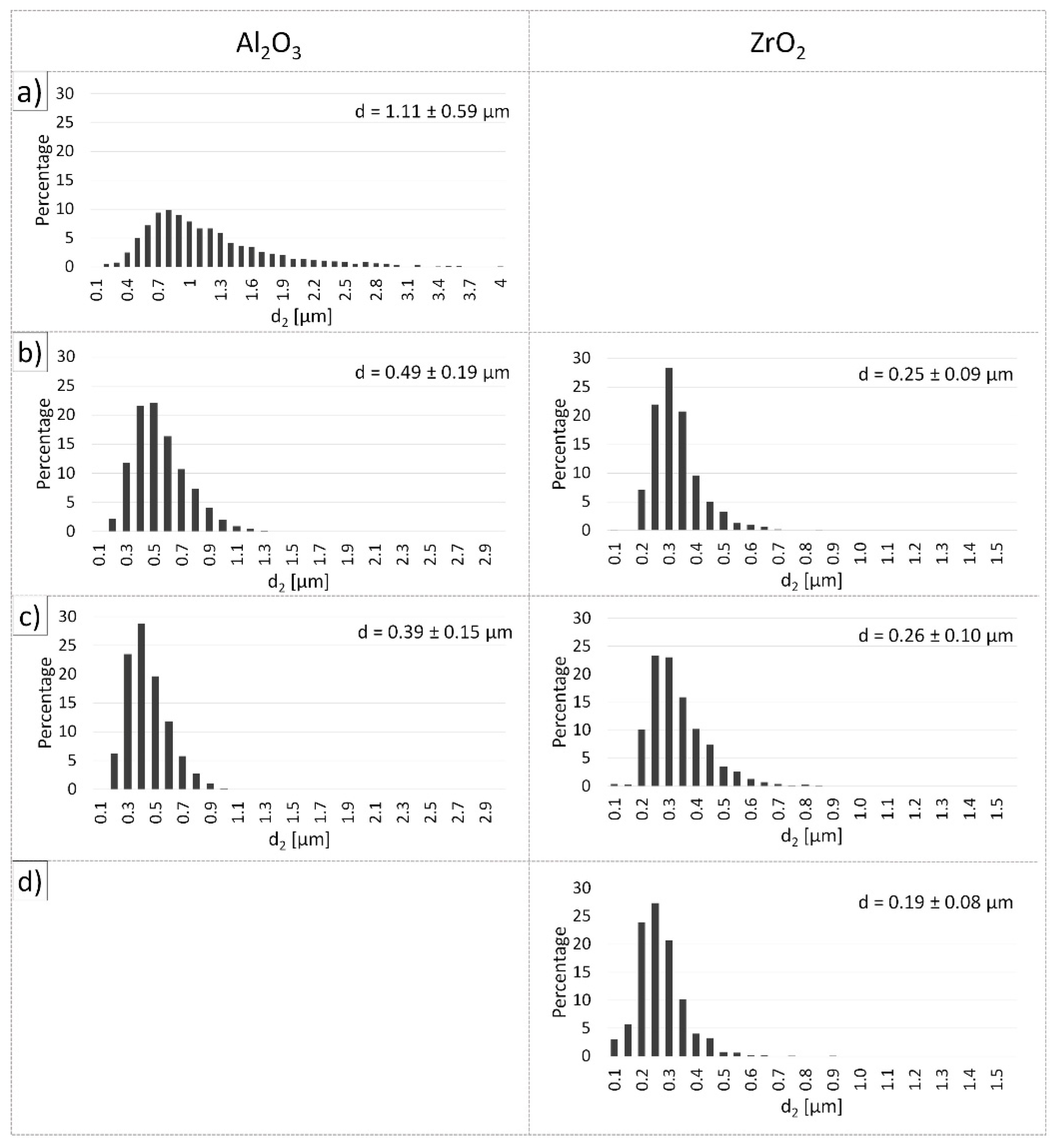
The obtained histograms of grain distribution in individual sinters are shown in
Figure 11. Moreover,
Table 6 exhibits the average grain sizes of Al
2O
3 and ZrO
2 in the obtained samples, as defined based on stereological analysis. The stereological analysis showed that the addition of ZrO
2 tackles the growth of Al
2O
3 grains. For the shapes of series I—100 vol.% Al
2O
3 it was found that Al
2O
3 grains ranged from 0.1 µm to 3.54 µm, and the average grain size of Al
2O
3 was 1.11 ± (3 × 0.59) µm. For ZTA composites containing 5 vol.% ZrO
2 (Series II), Al
2O
3 grains were found to range from 0.1 µm to 1.38 µm, while the average grain size of Al
2O
3 was 0.49 ± (3 × 0.19) µm. However, in the case of Series III—10 vol.% ZrO
2 it was observed that the Al
2O
3 grains ranged from 0.1 µm to 1.09 µm and the average grain size of Al
2O
3 was 0.39 ± (3 × 0.15) µm. The Al
2O
3 grain size results in the composites showed that the addition of ZrO
2 reduces grain growth by up to about 60%. It was noted that the Series IV shapes (100 vol.% ZrO
2) were characterised by the smallest ZrO
2 grain size of 0.19 ± (3 × 0.08) µm. These values are slightly higher than the average particle size of ZrO
2 in its raw state (0.15 ± (3 × 0.07) µm). The grain growth of ZrO
2 in Series IV samples relative to ZrO
2 in the raw state was about 22%. Histogram analysis showed that for both series of composites (Series II and Series III), the average ZrO
2 grain size was 0.25 ± (3 × 0.09) µm and 0.26 ± (3 × 0.01) µm for Series II and Series III, respectively. ZrO
2 grain growth for Series II and Series III was determined to be 40%—42% relative to the starting ZrO
2 powder (0.15 µm). All histograms of Al
2O
3 and ZrO
2 grain size distribution were unimodal.
In a further step of quantitative image analysis, three shape factors were determined: elongation, curvature of grain boundary and convexity. The obtained results of the analysis are summarised in
Table 7. The calculated values should be interpreted in relation to the shape of a circle. The more the shape of the tested grain is close to the circle, the value of the parameters is close to one.The stereological analysis showed that the Al
2O
3 grains in the samples from each series had a similar minimally elongated shape. This is confirmed by the determined values of shape parameters such as elongation (α). It was observed that the values of the index characterising the elongation of Al
2O
3 grains in all series assumed a unimodal distribution. In the case of ZrO
2-bearing samples, ZrO
2 grains for Series II and Series III were found to have a similar oval shape. In the case of Series IV, the ZrO
2 grains had a slightly elongated shape, as evidenced by the parameter α = 1.43.
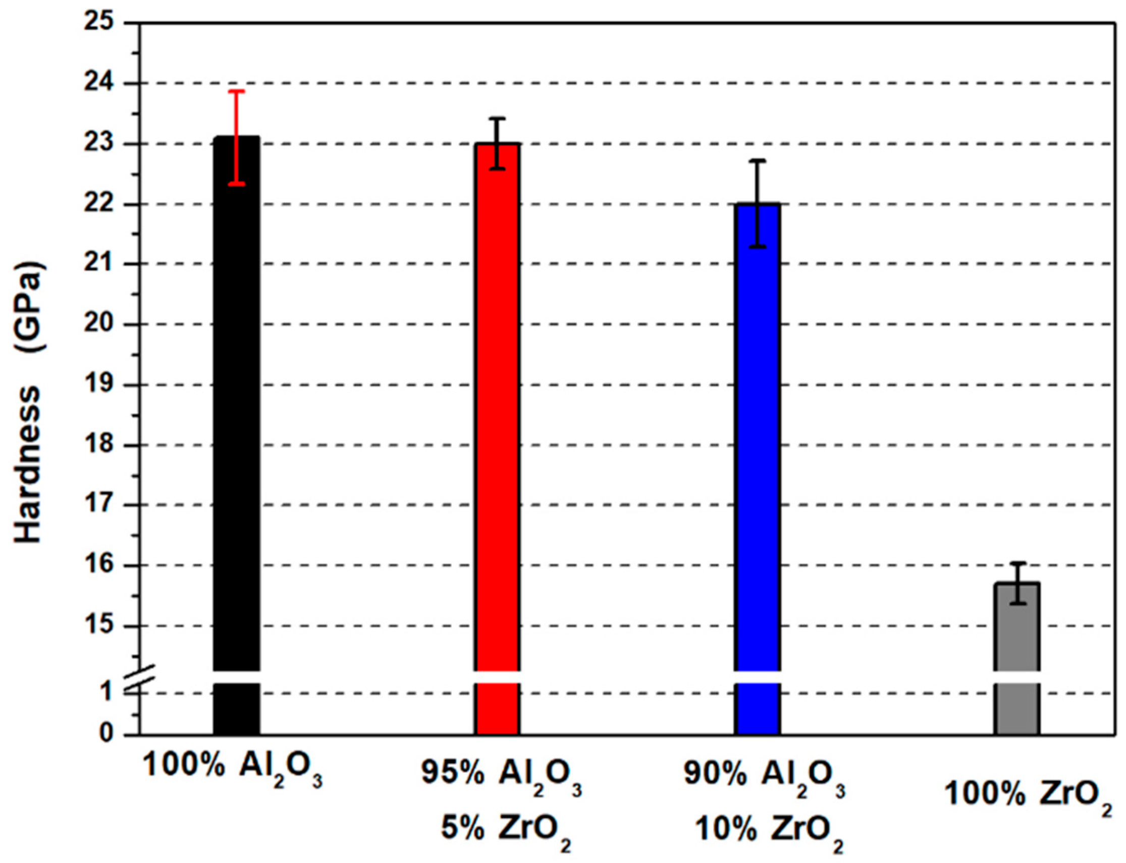
Hardness measurement results are presented in
Figure 12. Based on the obtained values, it was found that the shapes containing 100 vol.% Al
2O
3 (Series I) presented the highest hardness equal to 23.1 ± 0.77 GPa. These results are greater compared to the values reported by Pędzich et al. in their work [
44]. In his work, Pędzich obtained shapes with a hardness equal to 17.0 ± 1.2 GPa for samples made of Al
2O
3 powder (TM_DAR) formed by pressing [
44]. In turn, for shapes made from ZrO
2 powder (3Y-TZ), he obtained samples with a hardness of 14.0 ± 0.5 GPa [
44]. In the present study, shapes containing 100 vol.% ZrO
2 were characterised by a hardness equal to 15.75 ± 0.33 GPa. The values obtained for Series IV (100 vol.% ZrO
2) are also higher compared to literature data [
34]. In the work of Łada et al., a hardness equal to 11.87 ± 0.36 GPa was obtained for ZrO
2 shapes (TZ-3YS-E) formed by slip casting and sintered at 1450 °C [
45]. The high hardness values obtained in our own research both for the samples of 100% Al
2O
3 and ZrO
2 ceramics and Al
2O
3/ZrO
2 composites were most likely caused by the manufacturing method adopted—centrifugal slip casting.
The application of centrifugal force combined with the simultaneous action of capillary forces resulted in a dense packing of the ceramic particles, which was confirmed by the measured values of relative density which were close to complete compaction (100%). It was observed that the hardness values decreased with increasing ZrO2 content in the samples.
This is as expected, since the hardness of pure ZrO2 is lower than that of Al2O3. Hardness measurements showed that samples containing 5 vol.% ZrO2 (Series II) had a hardness of 23.0 ± 0.42 GPa, while Series III—10 vol.% ZrO2 had a hardness of 22.0 ± 0.72 GPa. It should be noted, however, that there are few literature reports on the production of composites from the Al2O3/ZrO2 system using the CSC method, so it is difficult to make a direct comparison of the results obtained with the scientific literature.
The environmental impacts accompanying the process of producing Al
2O
3/ZrO
2 sinters with ZrO
2 content of 0 vol.%, 5 vol.%, 10 vol.% and 100 vol.% are summarised in
Table 8. The results obtained indicate that with an increase in ZrO
2 content in the composite, there is a significant increase in the environmental impacts during the raw material acquisition and processing phase, which is directly related to the lower availability of zirconium in the Earth’s crust and the higher energy and material intensity of the process of obtaining ZrO
2 compared to Al
2O
3 [
46,
47]. The production of 1 kg of sinter results in greenhouse gas emissions, expressed in CO
2 equivalent, ranging from 2.24 kg CO
2 eq., 2.3 kg CO
2 eq. to 2.9 kg CO
2 eq. for 100% Al
2O
3, Al
2O
3/ZrO
2 and 100% ZrO
2, respectively, which is comparable to the emissions associated with the production of 1 kg of PVC, PP or hot-rolled steel products [
48,
49,
50]. The calculations take into account the fact that impacts associated with the transport of raw materials usually constitute no more than a few percent of the product stage [
51,
52]. At the same time, the impacts found at the sinter production stage—module A3, related, among others, to the use of electricity for the homogenisation of the casting slip, deareation, drying and sintering are incomparably higher and account for at least 80% of all the environmental impacts of the product stage (modules A1–A3) for all the sinters concerned. Such a distribution of environmental impacts at the product stage is typical of manufacturing processes carried out under non-optimised laboratory conditions. The results obtained clearly signal the need to carry out a qualitative and quantitative optimisation of process energy demand in the production of Al
2O
3/ZrO
2 sinters on an industrial scale.


 ,
, 


