
Electrical Performance of Polymer-Insulated Rail Brackets of DC Transit Subjected to Lightning Induced Overvoltage

 , ,
, ,  and
and
Abstract
1. Introduction
2. Case Study and Methods
2.1. The Kelana Jaya Line
2.2. Power Rails
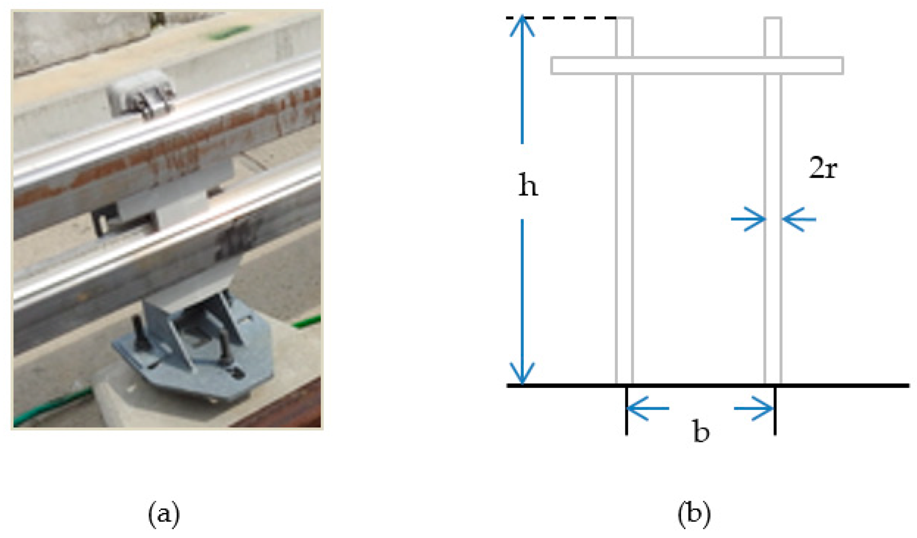
2.3. Insulated Rail Bracket
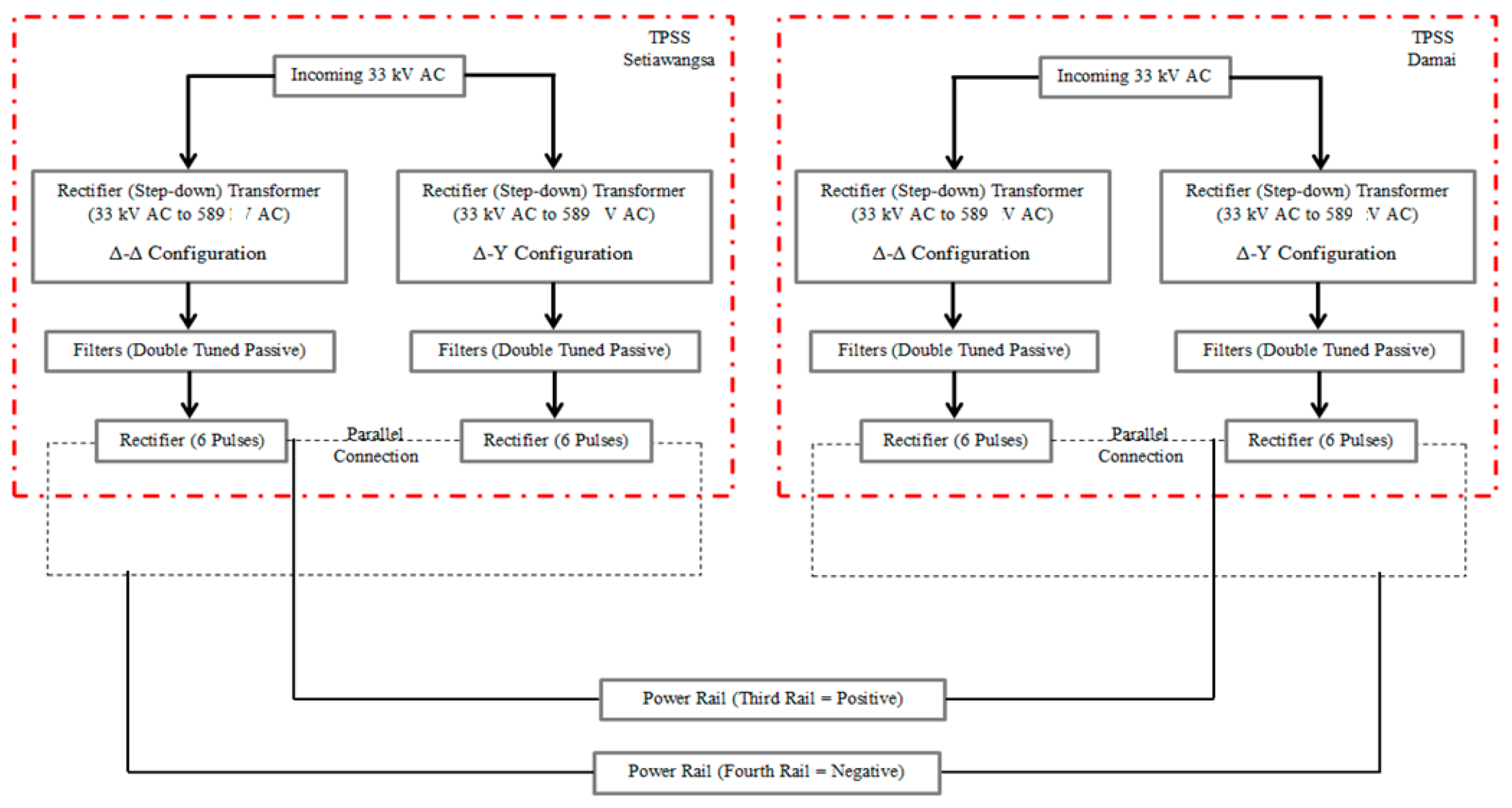
2.4. Traction Substation Surge Arrester
2.5. Indirect Lightning and LIOV Modelling
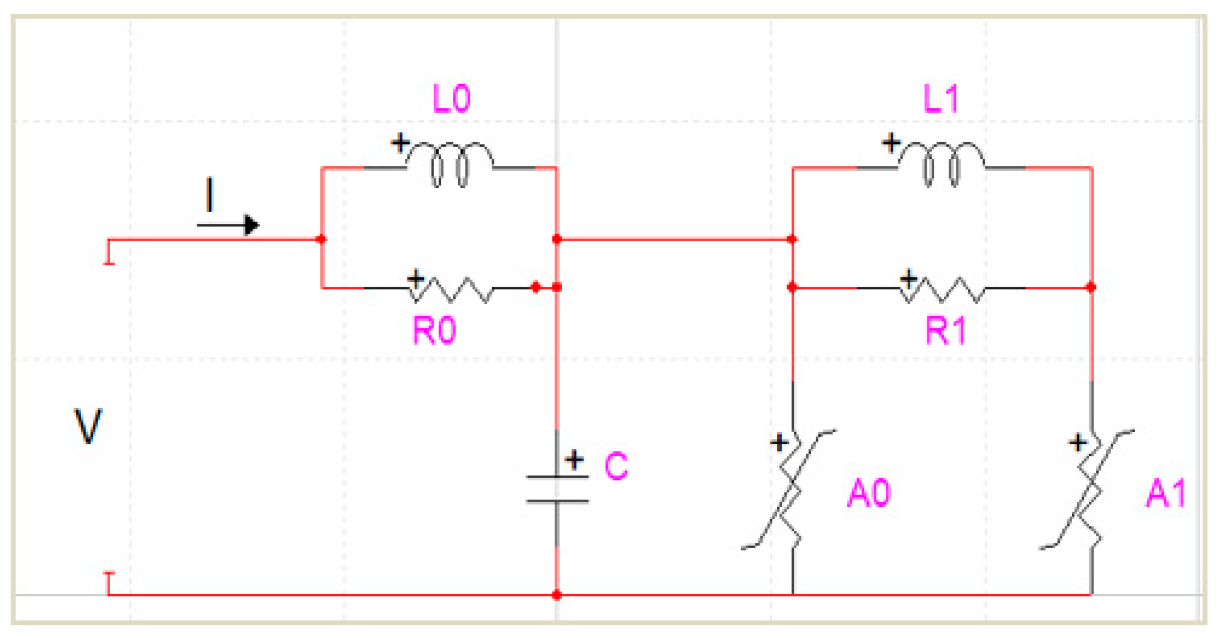
2.6. EMTP-RV Modelling
3. Results and Discussion
4. Conclusions
Author Contributions
Funding
Institutional Review Board Statement
Informed Consent Statement
Data Availability Statement
Acknowledgments
Conflicts of Interest
References
- Rahman, F.A.A.; Ab Kadir, M.Z.A.; Osman, M.; Amirulddin, U.A.U. Review of the AC Overhead Wires, the DC Third Rail and the DC Fourth Rail Transit Lines: Issues and Challenges. IEEE Access 2020, 8, 213277–213295. [Google Scholar] [CrossRef]
- Frey, S. Railway Electrification Systems & Engineering, 1st ed.; White Word Publications: Delhi, India, 2012. [Google Scholar]
- Railway Technology Webmaster. Railway Technology Kuala Lumpur. 2019. Available online: https://www.railway-technology.com/projects/kuala-lumpur-driverless-metro/ (accessed on 24 October 2019).
- Mohd Said, Z.F. Lightning Safety. MyHealth, Minist Heal Malaysia 2019. Available online: http://www.myhealth.gov.my/en/lightning-safety/ (accessed on 19 July 2020).
- Citizen Journalist Malaysia. Putra LRT subway service delayed after lightning. Citiz Journal Malaysia, 15 November 2010. [Google Scholar]
- Joibi, N. LRT service breaks down during peak hour. The Star, 11 December 2013. [Google Scholar]
- Polimac, V.; Jhutty, A.; Fraser, M. Application of HV Insulation Coordination Techniques to DC Railway Systems. High Volt. Eng. Symp. 1999, 2.372–2.376. [Google Scholar] [CrossRef]
- Wang, Y.-J.; Wang, J.-H. Modeling of frequency-dependent impedance of the third rail used in traction power systems. IEEE Trans. Power Deliv. 2000, 15, 750–755. [Google Scholar] [CrossRef]
- Grebovic, S. Energy Stresses of Transmission Line Surge Arresters Due to Lightning Discharges; Graz University of Technology: Graz, Austria, 2016. [Google Scholar]
- nVent Erico. nVent ERICO Lightning Protection Handbook; nVent Engineered Electrical & Fastening Solutions: Solon, OH, USA, 2018. [Google Scholar]
- Tiukaev, V.N. Fiber Glass Reinforced Plastic. The Great Soviet Encyclopedia. 1974. Available online: https://encyclopedia2.thefreedictionary.com/Fiber+Glass+Reinforced+Plastic (accessed on 29 July 2020).
- Synthane Taylor. Cast Epoxy Insulators. Synthane Taylor. 2018. Available online: http://www.synthanetaylor.com/cast-epoxy-insulators/ (accessed on 29 July 2020).
- Kultzow, R.; Foxhill, S. Cycloaliphatic Epoxy Resins. In Proceedings of the Thermoset Resin Formulators Association at the Hyatt Regency Savannah, Savannah, Georgia, 10–11 September 2007. [Google Scholar]
- Delfino, F.; Procopio, R.; Rossi, M. A Field-to-Line Coupling Model for Overvoltage Analysis in Light-Rail Transit DC Traction Power Systems. IEEE Trans. Power Deliv. 2005, 21, 270–277. [Google Scholar] [CrossRef]
- Cooray, V. An Introduction to Lightning, 1st ed.; Springers: Uppsala, Sweden, 2015. [Google Scholar]
- IEEE Power Engineering Society. 1243–1997: IEEE Guide for Improving the Lightning Performance of Transmission Lines; IEEE: New York, NY, USA, 1997. [Google Scholar] [CrossRef]
- Whitehead, J.T.; Chisholm, W.A.; Anderson, J.G.; Clayton, R.; Elahi, H.; Eriksson, A.J.; Grzybowski, S.; Hileman, A.R.; Janischewskyj, W.; Longo, V.J.; et al. Estimating Lightning Performance of Transmission Lines II—Updates to Analytical Models. IEEE Trans. Power Deliv. 1993, 8. [Google Scholar] [CrossRef]
- The Lightning Performance of Overhead Lines Working Group. IEEE STD 1410–2010: Guide for Improving the Lightning Performance of Electric Power Overhead Distribution Lines; IEEE: New York, NY, USA, 2011. [Google Scholar] [CrossRef]
- Zawani, N.; Junainah; Imran; Faizuhar, M. Modelling of 132kV Overhead Transmission Lines by using ATP/EMTP for Shielding Failure Pattern Recognition. Procedia Eng. 2013, 53, 278–287. [Google Scholar] [CrossRef]
- Shea, J. Insulation coordination for power systems. IEEE Electr. Insul. Mag. 2001, 17, 66. [Google Scholar] [CrossRef]
- Abu Bakar, H. Fast Transient Simulation of IEEE Recommended Surge Arrester Model on a Transmission Line Using Alternative Transient Program (ATP); Universiti Tun Hussien Onn Malaysia: Parit Raja, Malaysia, 2015. [Google Scholar]
- Muhamad, Y. Fast Transient Simulation of Pinceti Surge Arrester Model on a Transmission Line Using ATP Software; Universiti Tun Hussein Onn Malaysia: Parit Raja, Malaysia, 2015. [Google Scholar]
- Acer Voltage Ltd. Surge Arresters Overvoltage Limiters; Acer Voltage Ltd.: Hradec Kralove, Czech Reoublic, 2017. [Google Scholar]
- Hsiao, S.-J. Simulation and analysis of metal-oxide surge block arrester dynamic characteristics. J. Chin. Inst. Eng. 2013, 36, 598–607. [Google Scholar] [CrossRef]
- Team Railway Technology. DEHN Protects the Railway Infrastructure. DEHN SE + Co KG. Available online: https://www.dehn-international.com/en/dehn-protects-railway-technology (accessed on 3 September 2019).
- Izadi, M.; Ab Kadir, M.Z.A.; Hajikhani, M. On the Lightning Electromagnetic Fields due to Channel with Variable Return Stroke Velocity. Math. Probl. Eng. 2015, 2015, 1–9. [Google Scholar] [CrossRef]
- De Conti, A.; Visacro, S. Analytical Representation of Single- and Double-Peaked Lightning Current Waveforms. IEEE Trans. Electromagn. Compat. 2007, 49, 448–451. [Google Scholar] [CrossRef]
- Gamerota, W.R.; Elism, J.O.; Uman, M.A.; Rakov, V.A. Current Waveforms for Lightning Simulation. IEEE Trans. Electromagn. Compat. 2012, 54, 880–888. [Google Scholar] [CrossRef]
- Mottola, F. Methods and Techniques for the Evaluation of Lightning Induced Overvoltage on Power Lines. Application to MV Distribution Systems for Improving the Quality of Power Supply; University Federico II of Napoli: Napoli, Italy, 2007. [Google Scholar]
- EMTP-RV. An Introduction to EMTP-RV. The Reference for Power Systems Transients; EMTP-RV: Le Puy-Sainte-Réparade, France, 2012. [Google Scholar]
- Hirahara, K. Malaysia Kelana Jaya Line Power Supply System. Meiden Rev. 2012, 156, 48–51. [Google Scholar]
- RamaRao, G.; Chandrasekaran, K. Evaluating Lightning Channel-Base-Current Function Parameters for Identifying Interdependence of Wavefront and Tail by PSO Method. IEEE Trans. Electromagn. Compat. 2018, 61, 183–190. [Google Scholar] [CrossRef]
- Kenter, R.J. The Elevated Metro Structure in Concrete, UHPC and Composite. Master’s Thesis, Delft University of Technology, Delft, The Netherland, 2010. [Google Scholar]
- Zimackis, V. Methodology for Lightning Protection Device Placement in Medium Voltage Overhead Lines with Covered Conductors. Ph.D. Thesis, Riga Technical University, Riga, Latvia, 2018. [Google Scholar]
- Pingkai, J.; Chuanxiang, X.; Shoutai, W. Study of Dielectrical Properties of a New High Permittivity Material. In Proceedings of the Electrical Electronics Insulation Conference and Electrical Manufacturing & Coil Winding Conference, Rosemont, IL, USA, 18–21 September 1995; pp. 577–581. [Google Scholar]
- Paredes-Olguin, M.; Gomez-Yanez, C.; Espino-Cortes, F.; Ramirez, E. Electric stress grading on bushings of combined instrument transformers using high permittivity polymeric composites. IEEE Trans. Dielectr. Electr. Insul. 2013, 20, 2335–2342. [Google Scholar] [CrossRef]
- Littlefuse Inc. Surge Protection Device (SPD) FAQS & Definitions, 1st ed.; Littlefuse Inc.: Chicago, IL, USA, 2019. [Google Scholar]
- Siemens. Medium-Voltage Surge Arresters: Product Guide, 2017th ed.; Siemens: Munich, Germany, 2017. [Google Scholar]
- ABB Switzerland Ltd. Overvoltage Protection Metal-Oxide Surge Arresters in Medium-Voltage Systems (Application Guidelines), 6th ed.; ABB Switzerland Ltd.: Wettingen, Switzerland, 2018. [Google Scholar]


| Occurrence | Heidler Function Setting | I0 (kA) | |||
|---|---|---|---|---|---|
| % | I1 (kA) | τ11 (µs) | τ21 (µs) | n1 | I0 |
| 50 [32] | 9.075 | 3.42 | 40.24 | 2 | 30 (5/80 µs) |
| I2 (kA) | τ12 (µs) | τ22 (µs) | n2 | ||
| 20.515 | 4.793 | 153.46 | 10 | ||
| I1 (kA) | τ11 (µs) | τ21 (µs) | n1 | ||
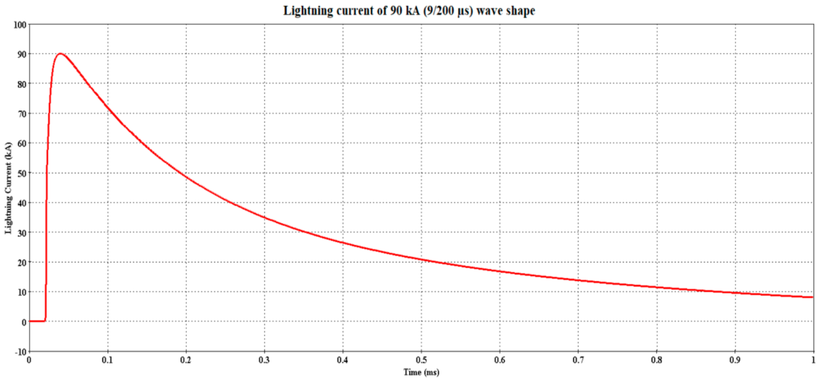
| 5 [32] | 46.49 | 5.86 | 143.997 | 2 | 90 (9/200 µs) |
| I2 (kA) | τ12 (µs) | τ22 (µs) | n2 | ||
| 41.548 | 41.759 | 592.86 | 10 | ||
| Operating System Voltage (V) | System Length (m) | Height (m) | Insulated Rail Bracket | Arrester(Residual Voltage (kV)) | I0 (kA) | Velocity (v) (108 m/s) | Strike Point | |
|---|---|---|---|---|---|---|---|---|
| Horizontal(d) (m) | Vertical (x) (m) | |||||||
| 750 | 3000 | 17 | CE | 3EB4-010 (2.4) | 30 and 90 | 1.2 | 25 | 2000 |
| CEA | ||||||||
| GRP | ||||||||
| Parameter | Value | Justification | |
|---|---|---|---|
| Guideway Height (m) | 17 | The proposed height follows the equation of span-to-height ratio of 3 as to create an aesthetical appearance. Furthermore, a higher elevation creates a more open and lighter area underneath the guideway [33]. | |
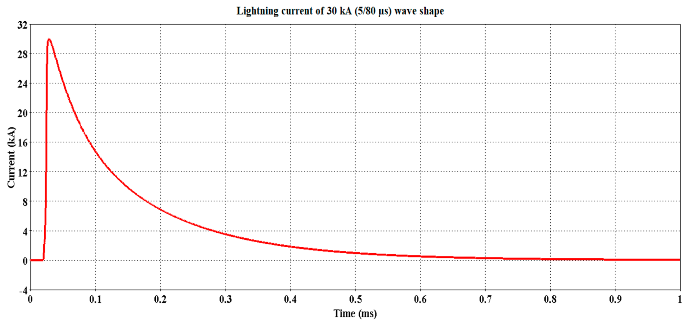
| Lightning | Current Peak (kA) | 30 and 90 | The selected magnitude is the typical magnitude of the negative first return stroke with 50% and 5% occurrences worldwide. The replication of the magnitude and its waveshape follows the assumption made towards the Heidler function parameters in the IEC 62305-1 [32]. |
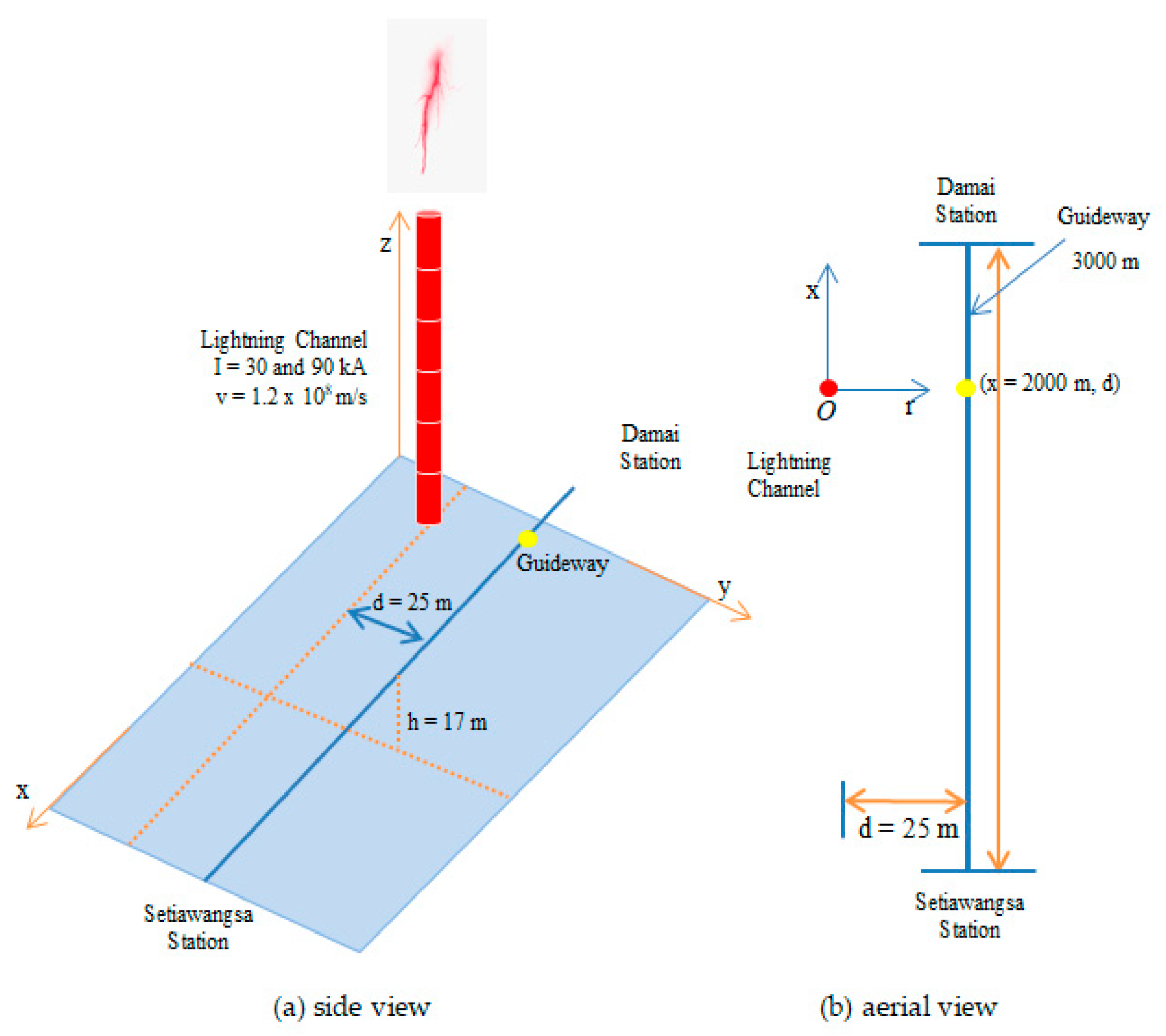
| Velocity (×108 m/s) | 1.2 | The selected velocity is the commonly accepted value as it lies in between c/3 and 2c/3, the typical velocities range of a return stroke lightning current, with c as the speed of light in free space; 2.99792458 × 10⁸ m/s [26,34]. | |
| Strike Distance | Horizontal (m) | 25 | The short distance is considered based on the fact that the LRT Kelana Jaya line runs through the heart of Greater Kuala Lumpur, a city that housed the majority of the Malaysia government administration buildings, businesses, entertainments, and leisure landmarks where void spaces between the guideway and the buildings are limited. In addition, 25 m is within the range of Protection Zone Law [34]; 2.5 to 80 m. |
| Vertical (m) | 2000 | The distances were selected for assessing the impact of induced overvoltages on the insulated rail bracket (2000 m). | |
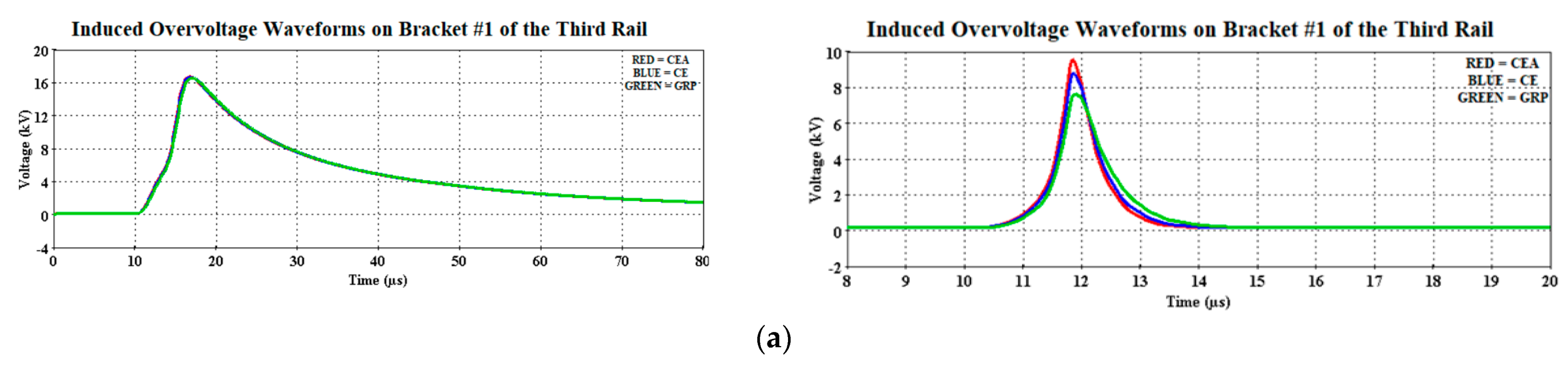
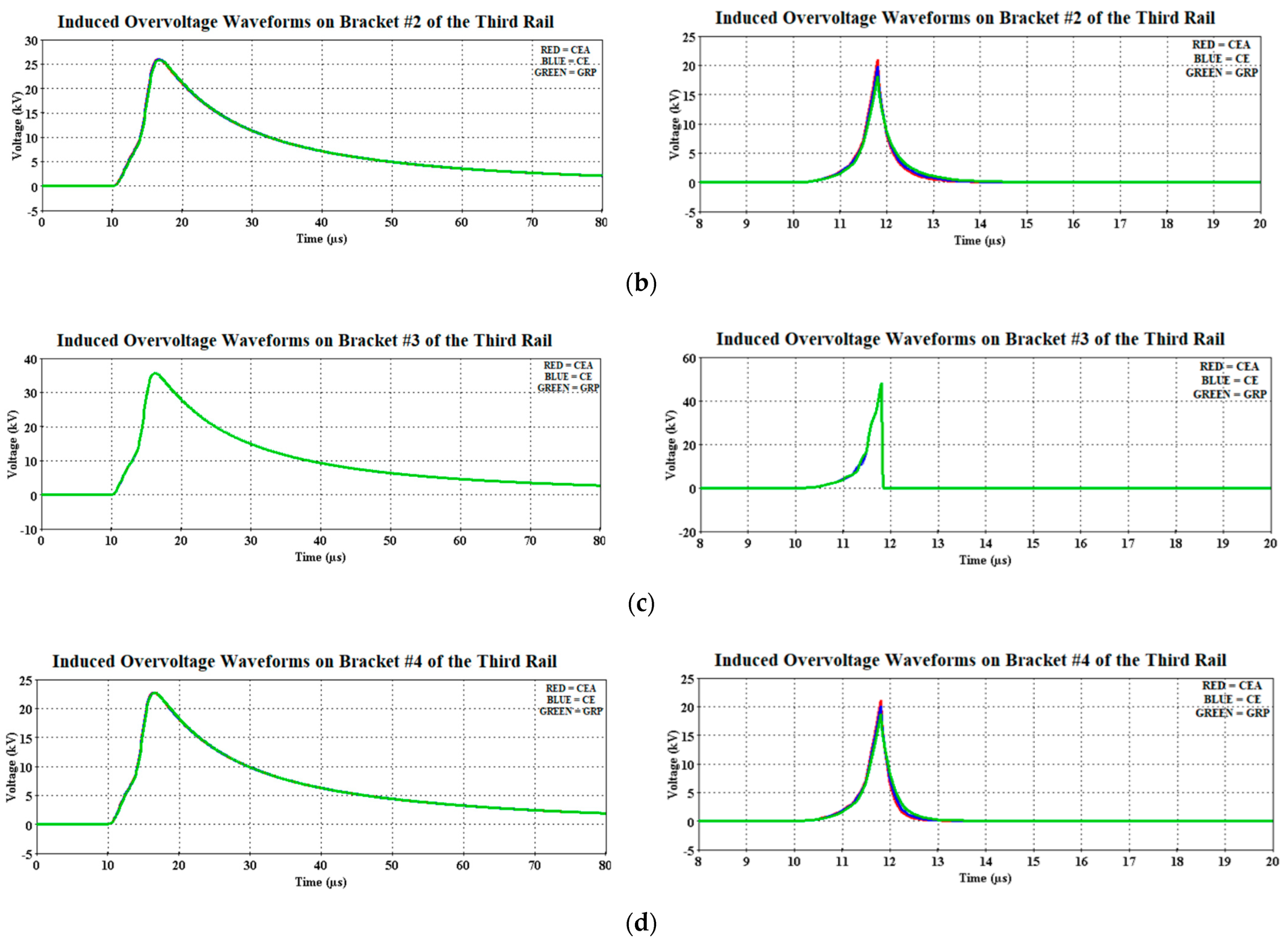
| Bracket Material | CE, CEA, GRP | The rail bracket is made from polymer-based materials, i.e., CE, CEA, and GRP which have a different permittivity value. | |
| Surge Arrester | 3EB4-010 10 kA at 8/20 µs and 2.4 kV | The selected surge arrester was based on its rated voltage (1.0 kV), MCOV (1.0 kV), and most importantly based on its residual voltage (2.4 kV) at a nominal discharge current (10 kA at 8/20 µs), the arrester energy limit is 10 kJ. | |
Publisher’s Note: MDPI stays neutral with regard to jurisdictional claims in published maps and institutional affiliations. |
© 2021 by the authors. Licensee MDPI, Basel, Switzerland. This article is an open access article distributed under the terms and conditions of the Creative Commons Attribution (CC BY) license (http://creativecommons.org/licenses/by/4.0/).
Share and Cite
Abd Rahman, F.A.; Ab Kadir, M.Z.A.; Ungku Amirulddin, U.A.; Osman, M. Electrical Performance of Polymer-Insulated Rail Brackets of DC Transit Subjected to Lightning Induced Overvoltage. Materials 2021, 14, 1684. https://doi.org/10.3390/ma14071684
Abd Rahman FA, Ab Kadir MZA, Ungku Amirulddin UA, Osman M. Electrical Performance of Polymer-Insulated Rail Brackets of DC Transit Subjected to Lightning Induced Overvoltage. Materials. 2021; 14(7):1684. https://doi.org/10.3390/ma14071684
Chicago/Turabian StyleAbd Rahman, Farah Asyikin, Mohd Zainal Abidin Ab Kadir, Ungku Anisa Ungku Amirulddin, and Miszaina Osman. 2021. "Electrical Performance of Polymer-Insulated Rail Brackets of DC Transit Subjected to Lightning Induced Overvoltage" Materials 14, no. 7: 1684. https://doi.org/10.3390/ma14071684
APA StyleAbd Rahman, F. A., Ab Kadir, M. Z. A., Ungku Amirulddin, U. A., & Osman, M. (2021). Electrical Performance of Polymer-Insulated Rail Brackets of DC Transit Subjected to Lightning Induced Overvoltage. Materials, 14(7), 1684. https://doi.org/10.3390/ma14071684