Article

The Effect of Electrochemical Composite Coatings with LaF3-LaB6 Particles in Nickel–Copper Matrix on the Metallurgical Processes in Arc Welding of Low Alloy Ferrite-Pearlite Steels

1
Institute of Mechanical Engineering, Materials and Transport, Peter the Great St.Petersburg Polytechnic University, Polytechnicheskaya, 29, St. Petersburg 195251, Russia
2
Chair of Materials Engineering of Additive Manufacturing, Department of Mechanical Engineering, Technical University of Munich, Boltzmann str. 15, 85748 München, Germany
*
Author to whom correspondence should be addressed.
Materials 2021, 14(6), 1509; https://doi.org/10.3390/ma14061509
Submission received: 24 February 2021 / Revised: 12 March 2021 / Accepted: 15 March 2021 / Published: 19 March 2021

Abstract

:
Development of welding consumables with fluorides and borides of rare earth metals is a promising area for improving the weldability of low alloy steels. As lanthanum fluoride and boride dissociate, lanthanum and boron dissolve in the weld pool and the welding arc plasma is saturated with fluorine. As a result of FeO, MnO, SiO2 deoxidation and FeS, MnS desulfurization, refractory lanthanum sulfides and oxides La2O3, La2S3 are formed in the weld pool, which can be the crystallization nuclei in the weld pool and the origin of acicular ferrite nucleation. The paper proposes a model of metallurgical processes in the arc and weld pool, as well as a model of electrochemical adsorption of Ni2+ cations in colloidal electrolytes during electrostatic deposition of nano-dispersed insoluble particles of LaF3 or LaB6 on the surface of wire. The paper discusses the constructional design of the welding wire and the technology for forming electrochemical composite coatings with copper and nickel matrix. The composite wires applied in the welding of low alloy steels make it possible to refine the microstructure, increase the tensile strength by 4% and the impact toughness of welds by 20%.

1. Introduction

Low alloy steels are widely used to produce welded structures in the ship-building, oil and gas pipeline transportation, wind turbines, and offshore platforms. Welded steel structures are used at low temperatures, often in hydrogen-containing and aggressive environments. The weldability of steels becomes more complicated due to the grain coarsening, hydrogen embrittlement, hydrogen-assisted cracking (HAC), and reduced impact toughness at low temperatures [1,2]. The main method that is used to weld these steels is a metal active gas (MAG) and metal inert gas (MIG) welding with solid wire, because it ensures the lowest level of diffusible hydrogen in welds [3,4].
The microstructural state of the weld metal and the heat-affected zone is the most important factor in the mechanism of hydrogen embrittlement, cracking and reduction in impact toughness [5,6]. The desired fine-grained microstructure is often achieved in welding using an optimal thermal cycle [7,8,9] and through minimizing the content of impurities and segregations making the grain structure more refined [10]. Another effective metallurgical solution is to refine the microstructure using a mechanism of heterogeneous grain nucleation at non-metallic inclusions and acicular ferrite when refractory oxides, sulfides, and nitrides are formed [11]. The most effective method for refining the microstructure is to design special welding wires and introduce rare earth metals (REMs) [12].
The refractory REM oxides and sulfides of type REM2O3, REM2S3 are non-metallic inclusions having a spherical shape similar to titanium oxides TiO, TiO2, Ti2O3 [13,14]. The oxides and sulfides of REMs have high melting temperatures, °C: La2O3 (2304); Y2O3 (2439); Ce2O3 (2250); ThO2 (3350); La2S3 (2110); Y2S3 (1925); Ce2S3 (2450); Th2S3 (2300) [15]. Thus, all these compounds formed in the weld pool increase the amount of crystallization nuclei, which contributes to the grain refinement of the microstructure and acicular ferrite nucleation [16,17]. Non-metallic spherical inclusions TiO, TiO2, Ti2O3 can also be the effective nuclei of acicular ferrite formation [18,19,20,21,22]. However, REMs have an advantage because they are more active in desulfurization and deoxidation reactions [23,24].
It is essential to highlight the importance of the borides of REMs in the mechanism of strengthening and refinement of the microstructure through the formation of refractory boron carbides B4C and boron nitrides BN [25]. Introducing boron has a positive effect on the properties and microstructure of cold-resistant austenitic steel with a small residual content of nitrogen being below 0.04% and boron being below 0.004%. This effect is related to the solubility of boron in γ-Fe and α-Fe, the reduction in harmful impurities of sulfur S and phosphorus P, and the formation of borides Me2B, Me5B3, Me3(C,B), Me23(C,B)6, FeMo2B4 [26].
In welding metallurgy, an important role is the formation of free fluorine as fluorides dissociate. It reduces the content of diffusible hydrogen due to the reactions in which hydrogen fluoride HF is formed [27]. The high effectiveness of fluorine and fluorides in removing hydrogen is explained by the metallurgical activity of fluorine and fluorides in the reactions with atomic H, molecular H2, and water vapor H2O both in liquid slag and in arc welding plasma [28].
Since pure metallic powders of REMs and boron have a high chemical activity, their direct introduction during welding leads to losses due to oxidation and evaporation. That is why to increase the transition coefficient of micro-alloying elements of REMs and boron in the weld pool, high-melting point compounds of REMs can be introduced in the form of fluorides and borides, whose properties are shown in Table 1.
The research is aimed at improving the mechanical properties of welds, refinement of the microstructure of welds using newly-designed welding wires with electrochemical composite coatings that contain lanthanum fluoride and boride nano-dispersed particles for welding low alloy ferrite-pearlite steels.

2. Materials and Methods

The arc welding was focused on using plates of S355 steel according to EN10025-3:2019 (10HSND steel according to GOST 19281-2014 in Russian) of 300 mm × 150 mm × 14 mm with G3Si1 wire (ESAB, Gothenburg, Kingdom of Sweden) according to EN ISO 14341-A, 1.2 mm in diameter, plates of S355 steel according to EN10025-3:2019 (09G2S steel according to GOST 19281-2014 in Russian) of 400 mm × 150 mm × 16 mm with S2Mo wire (ESAB, Gothenburg, Kingdom of Sweden) according to EN ISO 14171-A, 3 mm in diameter. In order to make composite wires, standard G3Si1, S2Mo wires were used with their surface being coated in composite electrochemical layers, 5–15 µm in thickness. The coatings consisted of a copper and nickel matrix and nano-dispersed LaF3 and LaB6 particles with a diameter of 0.3–0.7 µm. The parameters of the electrochemical process are shown in Table 2.
The set-up shown in Figure 1 was used to deposit composite coatings on welding wire.
In the technology that is used to form composite coatings, the welding wire goes in the continuous process into the etching and surface activation bath from 10% aqueous solution of H2SO4 at a feed rate of 0.5–2.5 m/min. The treatment at a temperature of 25 °C removes impurities, organic contaminants, and oxide films from the wire surface. Then the wire goes into the main electroplating bath containing colloidal electrolyte with nano-dispersed LaF3, LaB6 particles where the solution is thoroughly stirred. The processing time of the wire in each bath is 7–36 s. After the composite coating is formed, the wire goes into another bath of distilled water at a temperature of 60 °C to be cleansed from the remains of the electrolyte and then into the drying oven at a temperature of 115 °C. After that, the wire is wound in a coil.
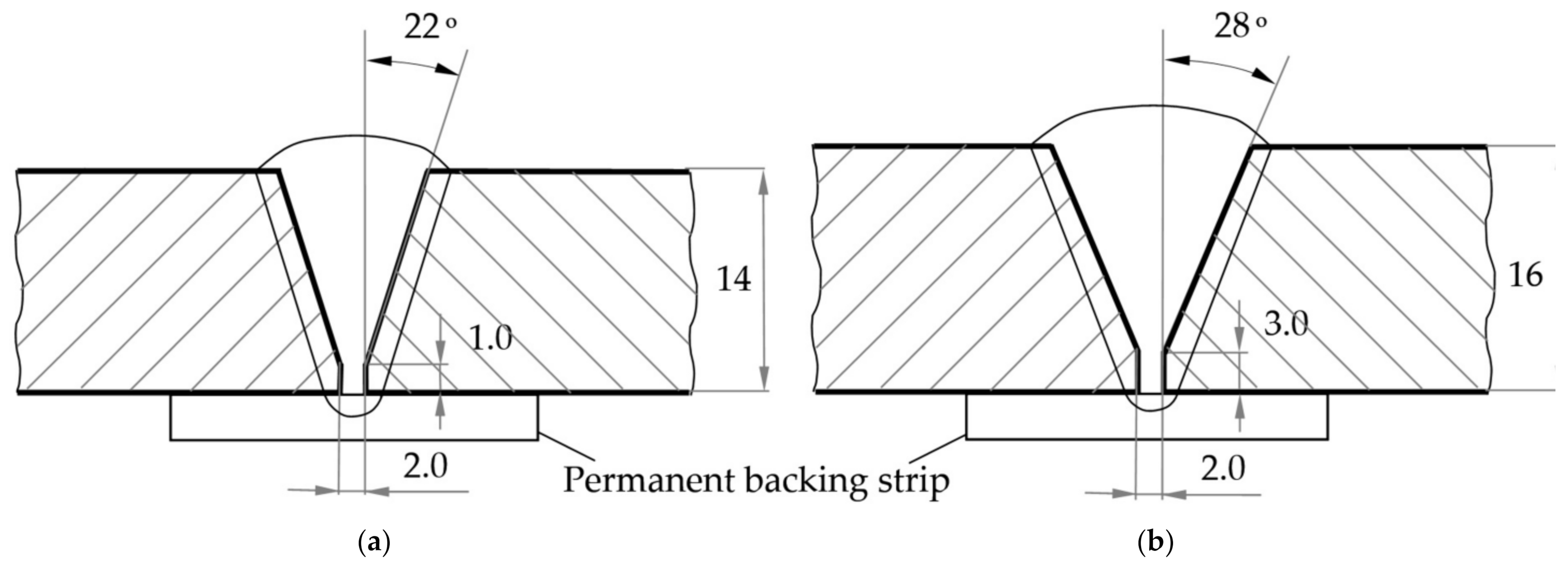
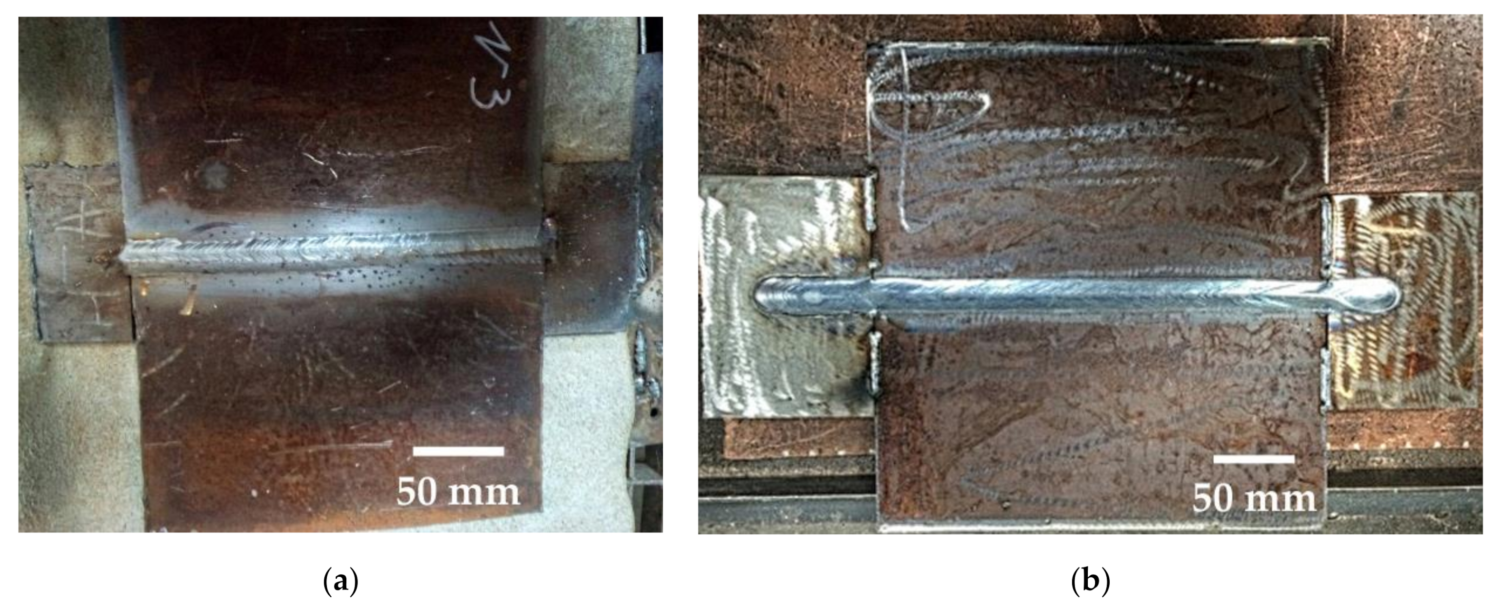
For MAG-welding of samples using a mixture of 82% of Ar and 18% of CO2, the following power sources were used an ESAB Origo MIG L405. For submerged arc welding (SAW) of plates made of 09G2S steel under a layer of OK Flux 10.71 (SiO2 + TiO2—20%; CaO + MgO—25%; Al2O3 + MnO—35%; CaF2—15%), an A2 Multitrack automatic welding machine with an LAF 1001 power source was used. The welding parameters are given in Table 3. The design of joints and appearance of the welds is shown in Figure 2 and Figure 3.
The metallurgical reactions and phase compositions were calculated using thermodynamic simulations based on the data of individual substances and using the software called IVTANTHERMO (Joint Institute for High Temperatures of the Russian Academy of Sciences, Moscow, Russia) and FactSage (CRCT, Montreal, Canada) [29,30]. A Tinius Olsen Model 602 machine (Tinius Olsen, Horsham, PA, USA) according to ISO 4136:2012, a PH450 pendulum impact testing machine (Walter + Bai AG, Löhningen, Switzerland) according to the standard testing of Charpy V-notch specimens to ISO 9016:2012, and an EMCOTEST DuraScan-20 hardness tester (EMCO-TEST PrufmaSchinen GmbH, Kuchl, Austria) according to ISO 9015-1:2001 were used for mechanical testing. The chemical composition was assessed using a Bruker Q4 TASMAN optical emission spectrometer (Bruker, Karlsruhe, Germany). Reichert-Jung Me F3A, Zeiss Axiovert 200 MAT microscopes (Carl Zeiss AG, Oberkochen, Germany) were used for optical metallography, while a SEM TESCAN MIRA 3 scanning microscope (Tescan Orsay Holding, Brno, Czech Republic) and a Bruker D8 Advance diffractometer (Bruker, Karlsruhe, Germany) were applied for X-ray analysis.

3. Results and Discussion

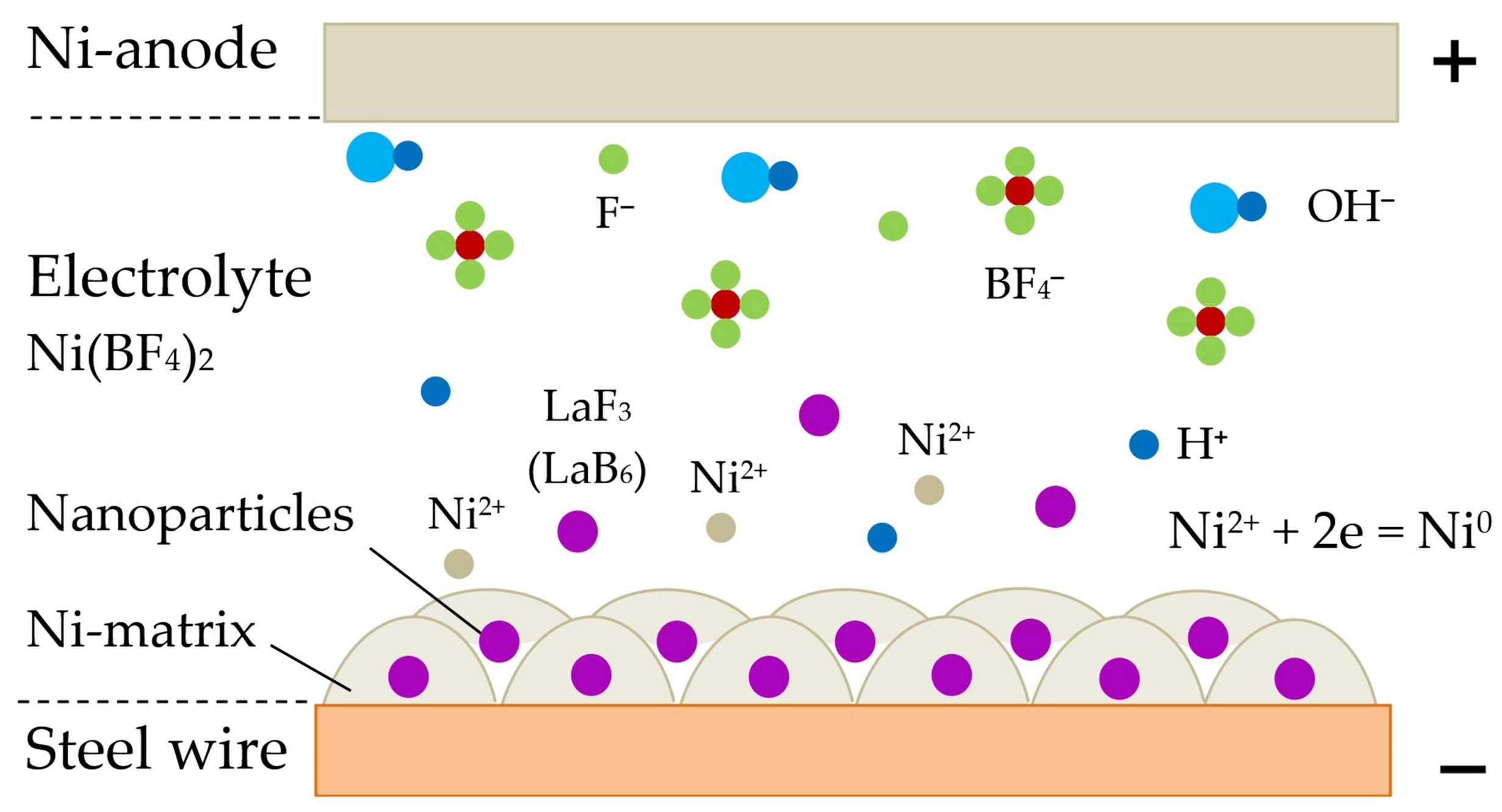
The mechanism according to which the composite coatings are formed in electrolyte with particles of rare earth compounds is shown in Figure 4.
Affected by electrostatic forces, insoluble LaF3 or LaB6 nanoparticles are attracted and deposited on the surface of the wire having a negative charge. The nickel cations Ni2+ or copper cations Cu2+ from the electrolyte and from the anode are neutralized on the surface of the cathode and form a metal layer over nanoparticles. OH, F, BF4− anions, which move in the opposite direction, are neutralized on the surface of the nickel anode and contribute to its erosion and enrichment of the electrolyte by nickel cations Ni2+. Thus, in a fast process, the composite is formed from the metallic matrix and nanoparticles. In case the composite Cu-coating is formed in electrolyte, copper cations Cu2+ and anions SO4− appear from copper sulfate CuSO4, and pure copper is used as anode.
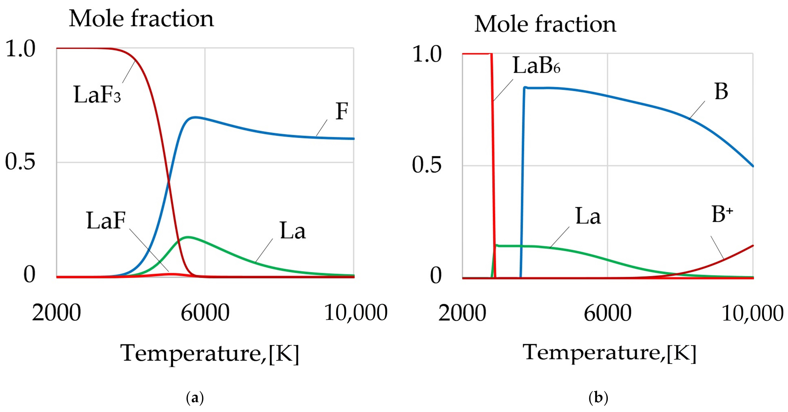
During welding, the wire with a composite coating consisting of nanoparticles and lanthanum compounds LaF3, LaB6 is melted and the molecules in the welding arc evaporate and dissociate into atomic La, F, B, as shown in Figure 5.
Then the atoms are ionized, which is proven by thermodynamic simulation of the phase composition, as shown in Figure 5. The dissociation products LaF3, LaB6 in the form of rare earth elements and boron are adsorbed on the melted surface of the wire and on the surface of the weld pool, after which they dissolve in the liquid metal. This helps to increase the activity of metallurgical processes by removing detrimental compounds and gases from the weld pool.
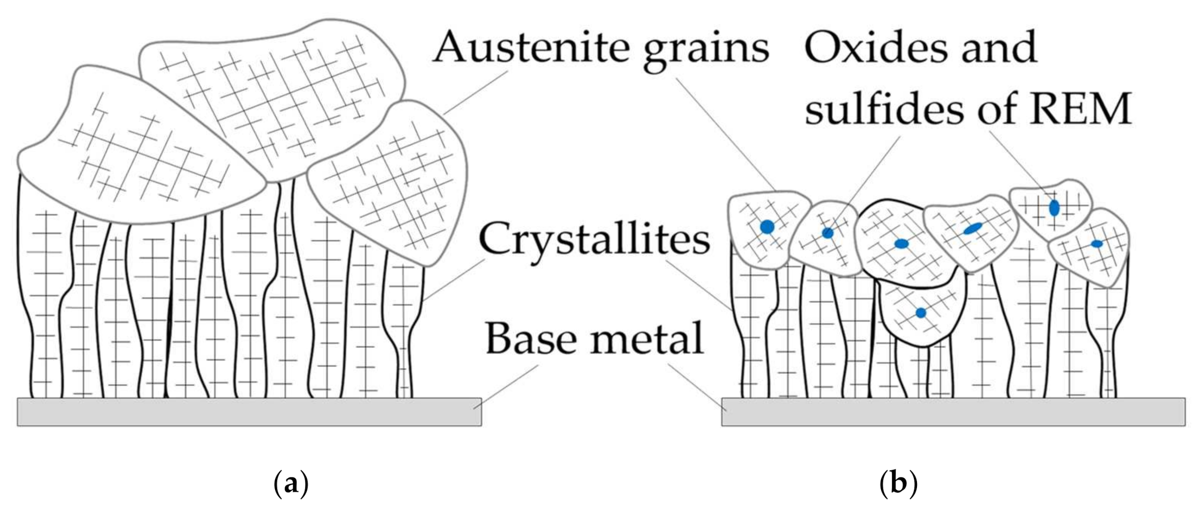
The weld pool always contains detrimental oxides FeO, SiO2, MnO, sulfides FeS, MnS, as well as diffusible elements S, H, N, which reduce the impact toughness, plasticity of welds and increase their sensitivity to hydrogen-assisted cracking. Enriching the weld pool with rare earth elements and boron leads to the interaction with harmful compounds and, as a result, refractory oxides and sulfides of REMs as well as boron nitrides BN are formed. They are the primary crystallization nuclei. Increasing the amount of refractory crystallization nuclei prevents large crystallites and dendrites from growing, which contributes to the refining of the primary austenite grains, as shown in Figure 6.
A similar mechanism of dendritic crystallization with additional crystallization nuclei, oxides, and sulfides is shown in other publications [31,32,33,34,35]. The austenitic grain size in the dendritic crystallization is reduced from 770 to 344 µm in columnar and equiaxed zones of primary crystallites, as shown in the study by Salas-Reyes et al. [36]. In case of further cooling, secondary crystallization takes place in pearlitic and bainitic transformation, and intragranular acicular ferrite nucleates inside austenite grains on the surface of refractory non-metallic inclusions, as shown in Figure 7.
This restrains cold cracks from propagation and increases the length its trajectory. Thus, oxides and sulfides of rare earth metals and boron nitride can stimulate the refining of the primary austenite microstructure and acicular ferrite nucleation in ferrite-pearlite steels [37,38,39]. Increasing the volume fraction of acicular ferrite and refining the microstructure of welds is an essential condition for increasing the impact toughness, reducing the critical temperature of ductile-brittle transition and decreasing the sensitivity to hydrogen-assisted cracking [40].
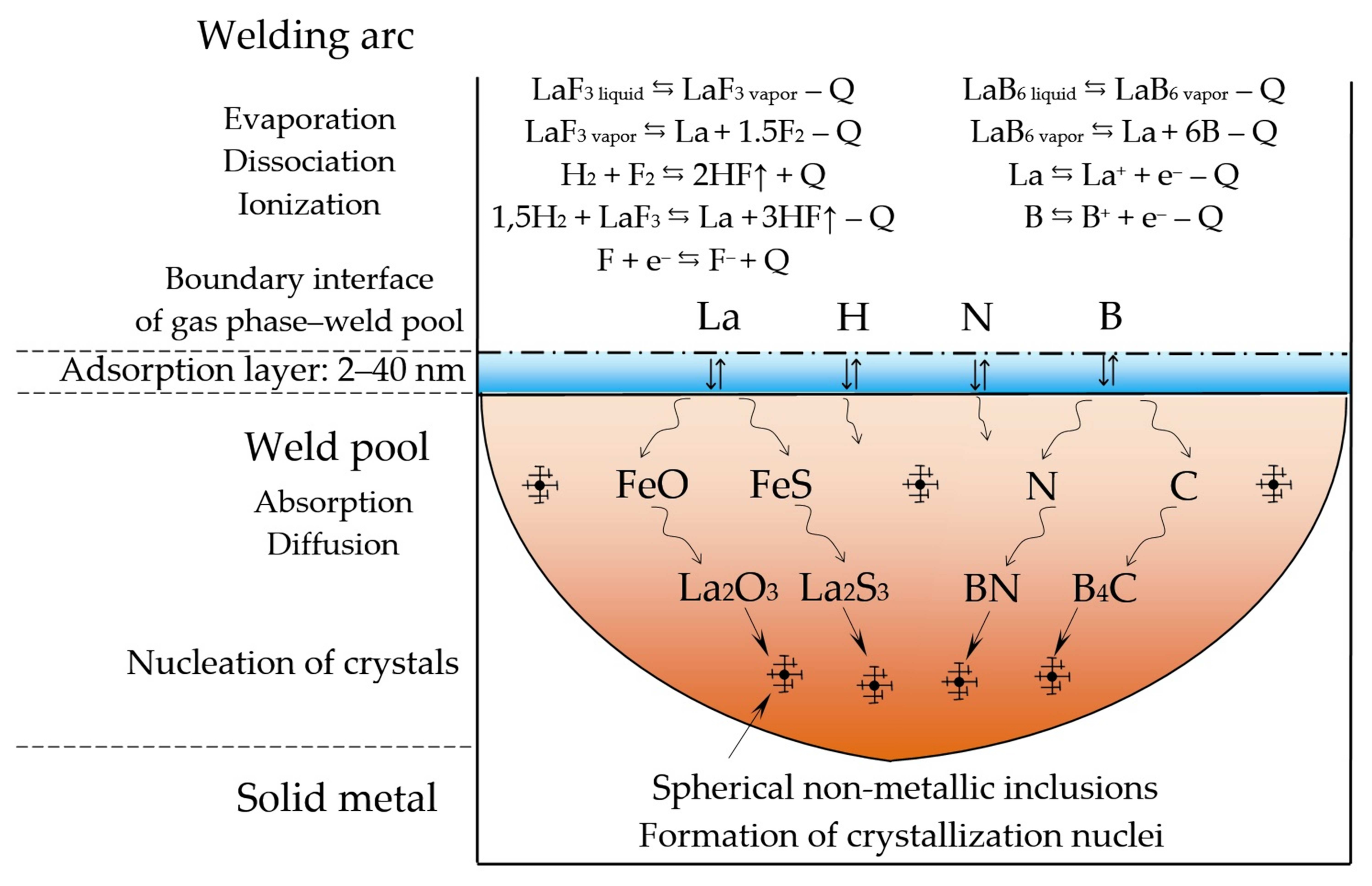
The model of metallurgical processes occurring in the welding arc and weld pool as LaF3 and LaB6 are introduced is shown in Figure 8.
After LaF3 and LaB6 dissociate, micro-alloying elements La and B are adsorbed on the surface of the weld pool and then dissolve in the weld pool. The thickness of the adsorption layer depends on the surface energy and gas composition. The adsorption layer thickness can be determined by the calculation method according to the Gibbs–Guggenheim definition [41]. According to the data by Lapshin et al. [42] the thickness of the adsorption layer reaches up to 40 nm. When the elements are distributed in the melt, there is metallurgical reaction of La with oxide FeO and sulfide FeS, and refractory oxide La2O3 and sulfide La2S3 are formed. When boron interacts with dissolved nitrogen and carbon, nitride BN and carbide B4C are formed. Apart from these reactions, possible reactions may include lanthanum and boron interacting with oxides and sulfides MnO, MnS, SiO2, as well as with diffusible elements—absorbed hydrogen, nitrogen, dissolved sulfur, and free oxygen. Since the atmosphere of the arc often contains water vapor and hydrogen, the binding of molecular hydrogen H2 in the atmosphere of the arc is important in compounds HF during the direct reaction of H2 interacting with fluorides of REMs and free fluorine.
A detailed analysis of the reactions between REMs and boron with diffusible elements as well as interaction with hydrogen in the welding arc plasma needs to be described separately and is outside the scope of this research.
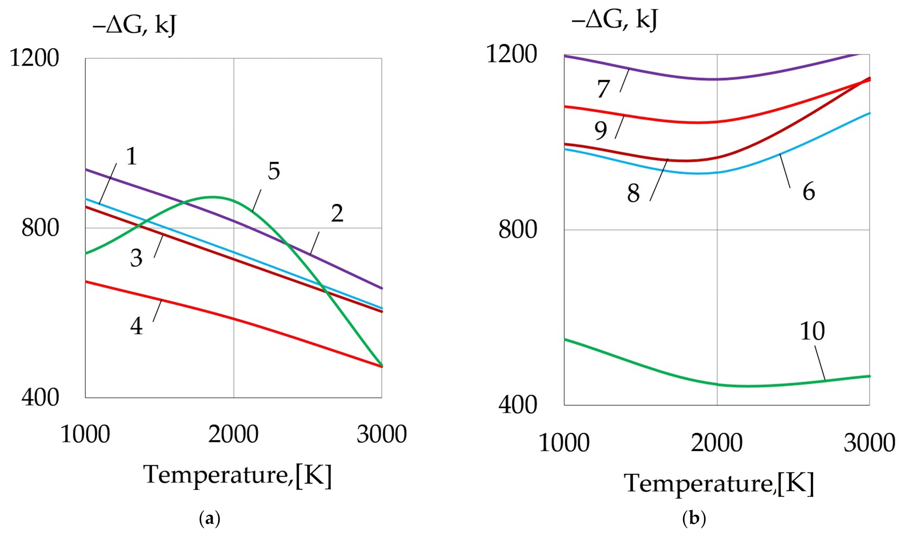
As a result of the metallurgical interaction, refractory non-metallic inclusions are formed in the weld pool, which are crystallization nuclei. The formation of the refractory oxides, sulfides and boron nitride can be explained with the high activity of dissolved rare earth elements and boron in the deoxidation and desulfurization reactions. The thermodynamic simulation confirms that the metallurgical reactions of deoxidation of FeO, SiO2 and desulfurization of FeS, MnS are highly probable. As rare earth metals La, Ce, Y, Th and boron are adsorbed and then dissolve in the weld pool, refractory oxides and sulfides of REMs, and boron nitride BN are formed according to Reactions (1)–(10), which have negative values of Gibbs free energy, as shown in Figure 9.
1.5FeO + 1.5FeS + 2La = 0.5La2O3 + 0.5La2S3 + 3Fe
1.5FeO + 1.5FeS + 2Y = 0.5Y2O3 + 0.5Y2S3 + 3Fe
1.5FeO + 1.5FeS + 2Ce = 0.5Ce2O3 + 0.5Ce2S3 + 3Fe
FeO + 1.5FeS + 1.5Th = 0.5ThO2 + 0.5Th2S3 + 2.5Fe
1.5FeO + 1.5FeS + N + 3B = 0.5B2O3 + 0.5B2S3 + BN + 3Fe
3MnS + 1.5SiO2 + 4La = La2O3 + La2S3 + 3Mn + 1.5Si
3MnS + 1.5SiO2 + 4Y = Y2O3 + Y2S3 + 3Mn + 1.5Si
3MnS + 1.5SiO2 + 4Ce = Ce2O3 + La2S3 + 3Mn + 1.5Si
3MnS + SiO2 + 3Th = ThO2 + Th2S3 + 3Mn + Si
MnO + SiO2 + N + 3B = B2O3 + BN + Mn + Si
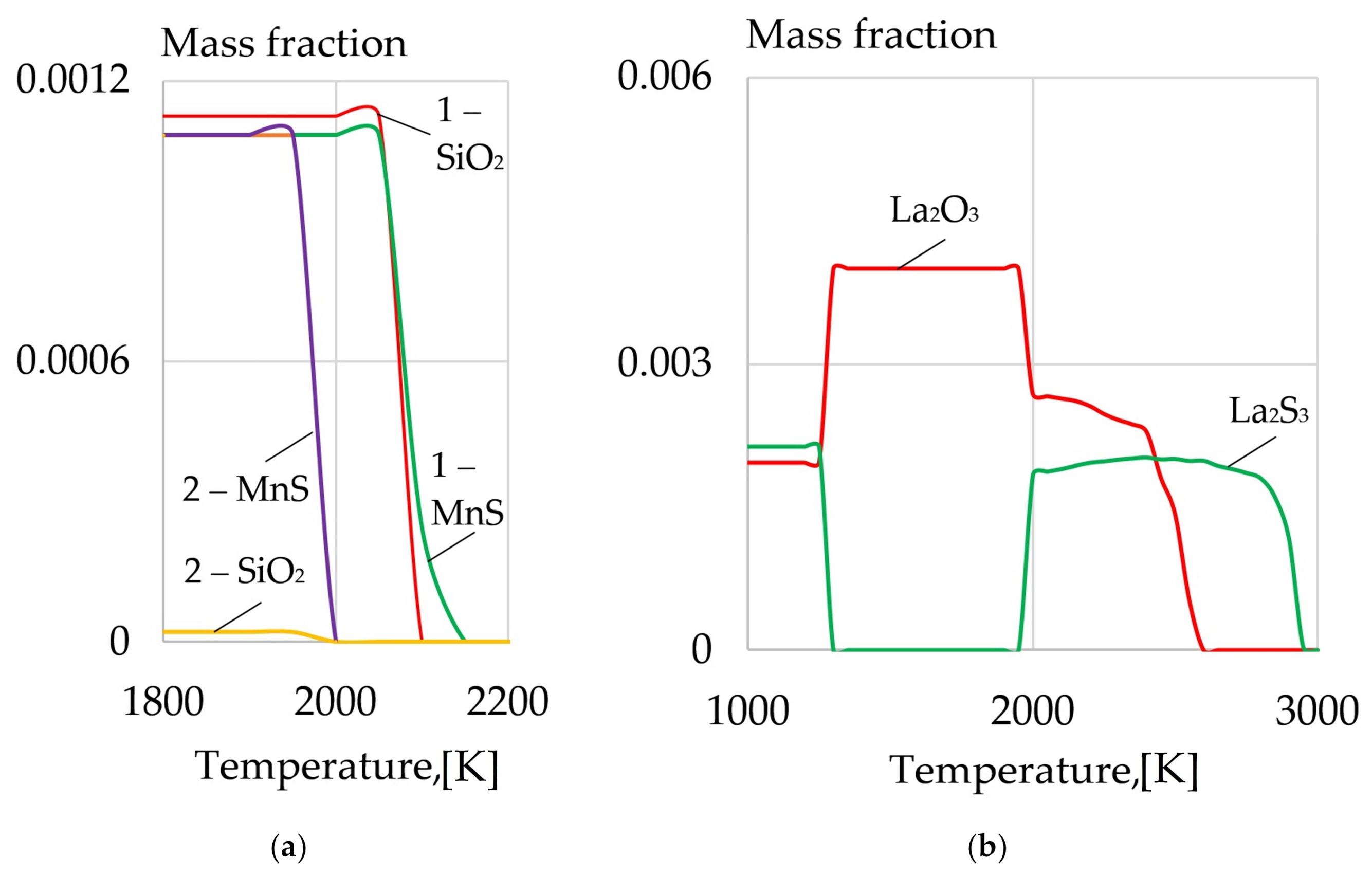
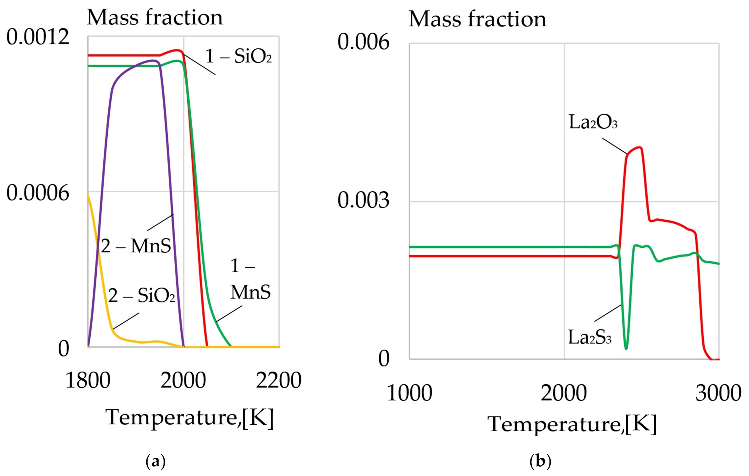
The thermodynamic modeling of the phase composition of the weld pool as 10HSND and 09G2S steels melt proves that with the introduction of LaF3 and LaB6, refractory sulfides and oxides of REMs are formed, as shown in Figure 10 and Figure 11. It causes the reduction in the content of S, O, SiO2, which are harmful impurities embrittling the weld because of the low-melting eutectics Fe-FeO, Fe-FeS, formed at the grain boundaries.
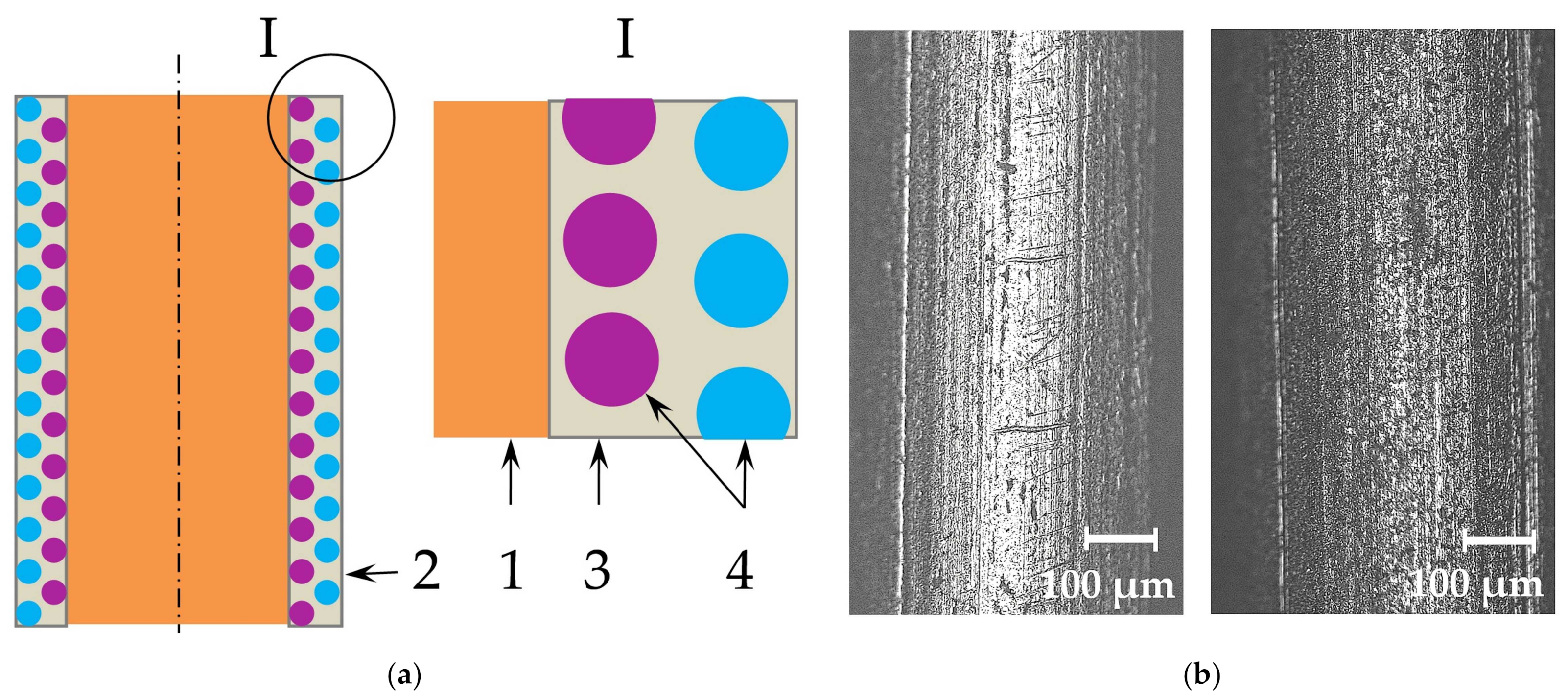
For effective introduction of REMs in the weld pool during welding of pearlitic steels, special design of the welding wire has been worked out. The design and the macrostructure of the composite wire are shown in Figure 12.
The wire is covered in an electrochemical composite coating with particles of REMs, which are evenly distributed inside the metal matrix coating. It ensures good electrical conductivity of the surface of the wire, which is important in the processes of automated and robotic welding.
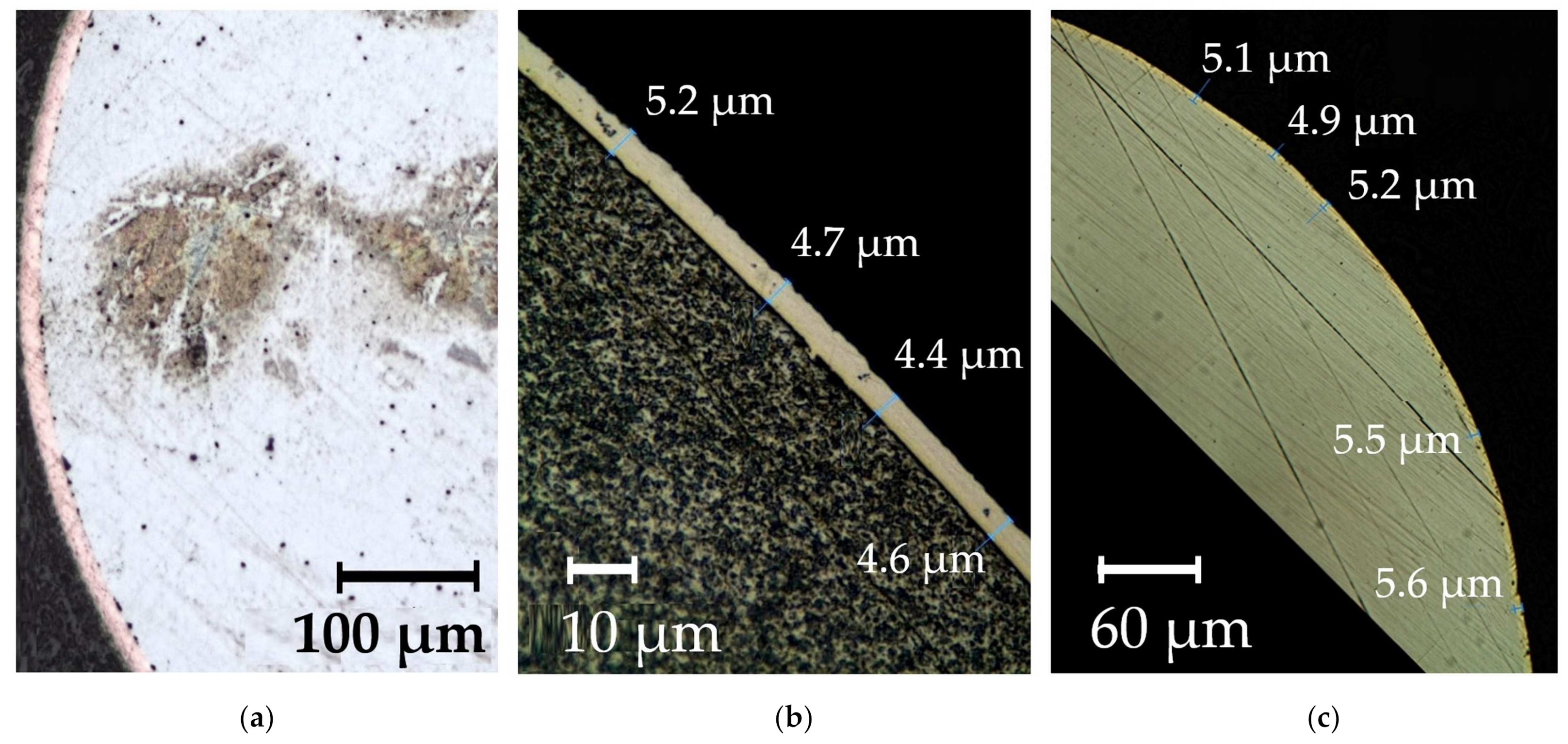
The electrochemical technology that is used to form nanocomposite coatings ensures high density and adhesion of the composite coating to the steel wire surface. Figure 13 shows the microstructure of the composite coatings on G3Si1 wires.
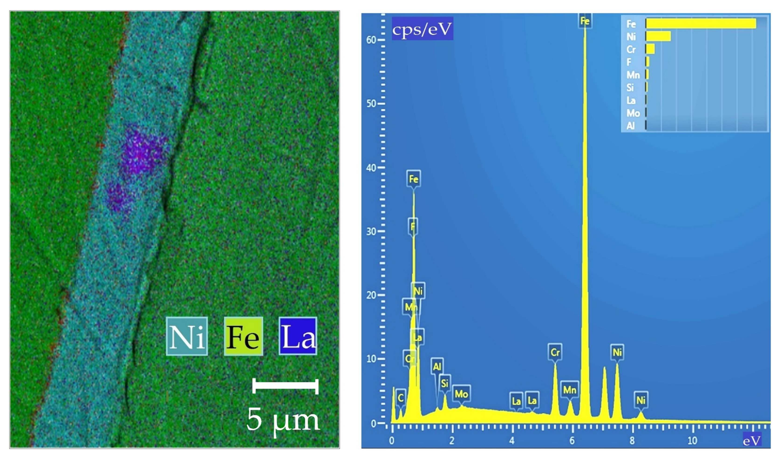
Figure 14 shows a typical SEM-elemental mapping of the composite Ni-LaF3 coating on G3Si1 wire.
According to X-ray structural analysis, typical Ni-LaF3 coating being about 5 µm in thickness contains up to 1.6 wt.% of La; up to 2 wt.% of La2Ni3; up to 0.2 wt.% of NiF3; and up to 96 wt.% of Ni.
The chemical analysis of weld metal in the weld center in 10HSND steel being 14 mm in thickness showed that as composite wires are applied, Cu, Ni, La, and Mn content insignificantly is increased. The content of other chemical elements did not change, as shown in Table 4.
According to the investigation of the mechanical properties of welds of 10HSND steel, using wire with Cu-LaF3 composite coating leads to an increase in tensile strength by 4%, and in impact toughness by 9.6–13.9%, as shown in Table 5.
Studying the mechanical characteristics of the welds on the plates made of 09G2S steel during submerged arc welding shows that if the wire with Ni-LaF3 composite coating is used, the impact toughness increases in the weld by 20.3%, and in the heat-affected zone by 11.4%, as shown in Table 6.
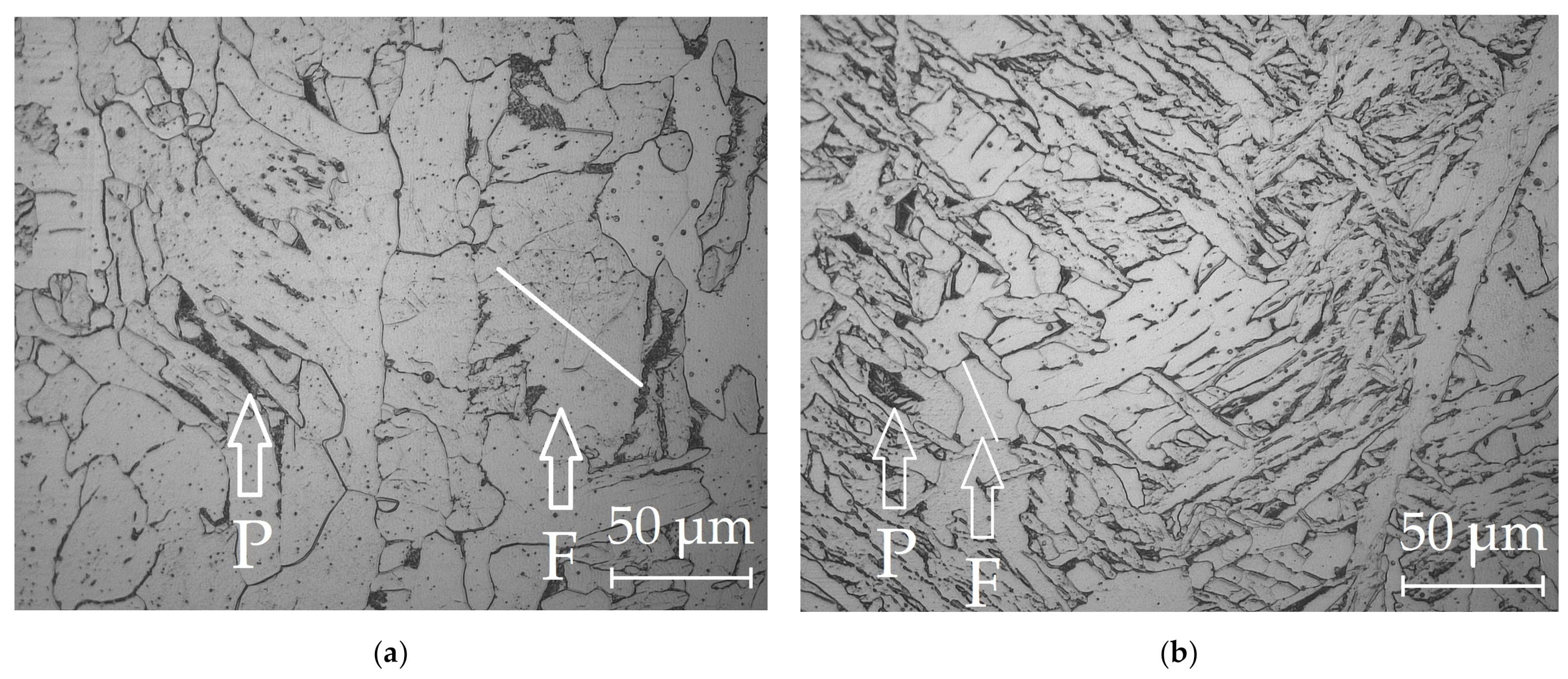
The improved mechanical properties are due to the refinement of the microstructure, as shown in Figure 15.
The improvement of the microstructure is a result of the positive effect of rare earth compounds in the reactions of deoxidation and refining of grain boundaries from harmful segregations and impurities. Another reason for the improvement of mechanical properties can be the grain refinement due to the formation of refractory oxides and sulfides of lanthanum and the inhibition of growth of primary crystallites during solidification. The analysis of the microstructure of the weld metal shows that using composite wires with nano-dispersed particles of LaF3 and LaB6 leads to refinement of the microstructure, to a reduced average size of the grain from 40–60 µm to 12–28 µm for G3Si1 wire, to better morphology and even distribution of microstructural phases.

4. Conclusions

  • A model of the metallurgical processes for arc welding of low alloy pearlitic steels was proposed. It considers the formation of refractory sulfides and oxides of REMs as the crystallization nuclei in the weld pool and centers of acicular ferrite nucleation. Refractory non-metallic inclusions of oxides and sulfides of type REM2O3, REM2S3, and nitride BN can be formed in the weld pool due to a mechanism of the exchange reactions of FeO, MnO, SiO2 deoxidation and FeS, MnS desulfurization as they interact with rare earth elements La, Y, Ce, Th, and boron B. During the heating of the composite coating, the fluorides and borides of REMs dissociate and the micro-alloying elements are adsorbed on the surface of the molten droplets and weld pool. As a result, the weld pool is saturated with REMs and boron and active metallurgical treatment becomes possible. Due to the formation refractory sulfides and oxides of REMs, the growth of crystallites and austenite grains is limited, the microstructure is refined, and the strength and impact toughness of the welds at low temperatures increases.
  • Improving weldability and microstructure of pearlitic steel welds can be achieved thanks to the progressive design of the composite wire and the technology of its manufacturing, which imply that the composite coating is formed from copper and nickel matrix with nano-dispersed particles of fluorides and borides of REMs. A model is suggested for electrochemical adsorption of Ni2+ and Cu2+ cations with electrostatic deposition of nano-dispersed insoluble particles on the wire surface and subsequent formation of composite coatings in colloidal electrolytes based on Ni(BF4)2 and CuSO4 in ethanol C2H6O and distilled water H2O.

Author Contributions

Conceptualization, S.G.P.; methodology, S.G.P. and V.A.K.; software, V.A.K.; validation, S.G.P., V.A.K. and A.S.M.; formal analysis, A.S.M.; investigation, A.S.M.; resources, P.M.; data curation, P.M.; writing—original draft preparation, S.G.P.; writing—review and editing, P.M.; visualization, S.G.P.; supervision, S.G.P.; project administration, S.G.P.; funding acquisition, P.M. All authors have read and agreed to the published version of the manuscript.

Funding

This research was supported by the project “Energy-efficient systems based on renewable energy for Arctic conditions” (EFREA), KS1054, South-East Finland-Russia CBC Program 2014–2020 and by the German Academic Exchange Service, Program 2018 (57381327).

Institutional Review Board Statement

Not Applicable.

Informed Consent Statement

Not Applicable.

Data Availability Statement

Data sharing is not applicable.

Conflicts of Interest

The authors declare no conflict of interest.

References

  1. Villalobos, J.C.; Del-Pozo, A.; Campillo, B.; Mayén, J.; Serna, S. Microalloyed Steels through History until 2018: Review of Chemical Composition, Processing and Hydrogen Service. Metals 2018, 8, 351. [Google Scholar] [CrossRef] [Green Version]
  2. Li, J.; Li, H.; Liang, Y.; Liu, P.; Yang, L. The microstructure and mechanical properties of multi-strand, composite welding-wire welded joints of high nitrogen austenitic stainless steel. Materials 2019, 12, 2944. [Google Scholar] [CrossRef] [PubMed] [Green Version]
  3. Schaupp, T.; Rhode, M.; Yahyaoui, H.; Kannengiesser, T. Influence of heat control on hydrogen distribution in high-strength multi-layer welds with narrow groove. Weld. World 2019, 63, 607–616. [Google Scholar] [CrossRef]
  4. Viyanit, E.; Keawkumsai, S.; Wongpinkeaw, K.; Bunchoo, N.; Khonraeng, W.; Trachoo, T.; Boellinghaus, T. Hydrogen assisted cracking of an AISI 321 stainless steel seamless pipe exposed to hydrogen-containing hot gas at high pressure. Eng. Fail. Anal. 2019, 100, 288–299. [Google Scholar] [CrossRef]
  5. Artola, G.; Arredondo, A.; Fernández-Calvo, A.I.; Aldazabal, J. Hydrogen Embrittlement Susceptibility of R4 and R5 High-Strength Mooring Steels in Cold and Warm Seawater. Metals 2018, 8, 700. [Google Scholar] [CrossRef] [Green Version]
  6. Miletić, I.; Ilić, A.; Nikolić, R.R.; Ulewicz, R.; Ivanović, L.; Sczygiol, N. Analysis of Selected Properties of Welded Joints of the HSLA Steels. Materials 2020, 13, 1301. [Google Scholar] [CrossRef] [PubMed] [Green Version]
  7. Królicka, A.; Ambroziak, A.; Żak, A. Welding Capabilities of Nanostructured Carbide-Free Bainite: Review of Welding Methods, Materials, Problems, and Perspectives. Appl. Sci. 2019, 9, 3798. [Google Scholar] [CrossRef] [Green Version]
  8. Królicka, A.; Radwański, K.; Janik, A.; Kustroń, P.; Ambroziak, A. Metallurgical Characterization of Welded Joint of Nanostructured Bainite: Regeneration Technique versus Post Welding Heat Treatment. Materials 2020, 13, 4841. [Google Scholar] [CrossRef]
  9. Szymczak, T.; Makowska, K.; Kowalewski, Z.L. Influence of the Welding Process on the Mechanical Characteristics and Fracture of the S700MC High Strength Steel under Various Types of Loading. Materials 2020, 13, 5249. [Google Scholar] [CrossRef]
  10. Nunes, A.R.V.; Zeemann, A.; De Almeida, L.H. The contribution of impurities to unexpected cold cracks in a thick C-Mn steel plate. J. Mater. Res. Technol. 2019, 8, 4364–4373. [Google Scholar] [CrossRef]
  11. Yi, H.-J.; Lee, Y.-J.; Kim, J.-Y.; Kang, S.-S. Effect of microstructure and chemical composition on cold crack susceptibility of high-strength weld metal. J. Mech. Sci. Technol. 2011, 25, 2185–2193. [Google Scholar] [CrossRef]
  12. Pan, F.; Zhang, J.; Chen, H.-L.; Su, Y.-H.; Kuo, C.-L.; Chen, S.-H.; Lin, K.-J.; Hsieh, P.-H.; Hwang, W.-S. Effects of Rare Earth Metals on Steel Microstructures. Materials 2016, 9, 417. [Google Scholar] [CrossRef] [Green Version]
  13. Shang, Z.; Li, T.; Yang, S.; Yan, J.; Guo, H. Three-dimensional characterization of typical inclusions in steel by X-ray Micro-CT. J. Mater. Res. Technol. 2020, 9, 3686–3698. [Google Scholar] [CrossRef]
  14. Seo, K.; Kim, Y.-M.; Evans, G.M.; Kim, H.J.; Lee, C. Formation of Mn-depleted zone in Ti-containing weld metals. Weld. World 2015, 59, 373–380. [Google Scholar] [CrossRef]
  15. Haynes, W.M. CRC Handbook of Chemistry and Physics, 97th ed.; CRC Press: Boulder, CO, USA, 2017. [Google Scholar]
  16. Adabavazeh, Z.; Hwang, W.S.; Su, Y.H. Effect of Adding Cerium on Microstructure and Morphology of Ce-Based Inclusions Formed in Low-Carbon Steel. Sci. Rep. 2017, 7, 46503. [Google Scholar] [CrossRef]
  17. Nako, H.; Okazaki, Y.; Speer, J.G. Acicular Ferrite Formation on Ti-Rare Earth Metal-Zr Complex Oxides. ISIJ Int. 2015, 55, 250–256. [Google Scholar] [CrossRef] [Green Version]
  18. Milani, J.M.; Saeid, T. Acicular ferrite nucleation and growth in API5L-X65 steel submerged arc welded joints. Mater. Sci. Technol. 2020, 36, 1398–1406. [Google Scholar] [CrossRef]
  19. Wang, B.; Liu, X.; Wang, G. Inclusion characteristics and acicular ferrite nucleation in Ti-containing weld metals of X70 pipeline steel. Steel Res. Int. 2018, 89, 1–11. [Google Scholar] [CrossRef]
  20. Cai, Z.; Kong, H. Inclusion and Microstructure Characteristics in a Steel Sample with TiO2 Nanoparticle Addition and Mg Treatment. Metals 2019, 9, 171. [Google Scholar] [CrossRef] [Green Version]
  21. Evans, G.M. Microstructure and properties of ferritic steel welds containing Ti and B. Weld. J. 1996, 75, 251–260. [Google Scholar]
  22. Blais, C.; L’Esperance, G.; Evans, G.M. Characterization of inclusions found in C-Mn steel welds containing titanium. Sci. Technol. Weld. Join. 1999, 4, 143–150. [Google Scholar] [CrossRef]
  23. Drápala, J.; Brožová, S.; Szurman, I.; Konečná, K.; Kostiuková, G.; Vontorová, J.; Jonšta, P.; Sobotková, K. Influence of selected rare earth metals on structural characteristics of 42CrMo4 steel. Metalurgija 2016, 55, 757–760. [Google Scholar]
  24. Luo, S.; Shen, Z.; Yu, Z.; Wang, W.; Zhu, M. Effect of Ce Addition on Inclusions and Grain Structure in Gear Steel 20CrNiMo. Steel Res. Int. 2021, 92, 1–20. [Google Scholar] [CrossRef]
  25. Wang, Y.; Yan, Q. Microstructure and strengthening mechanism of grain boundary strengthened W-ZrB2 alloy. J Mater. Res. Technol. 2020, 9, 4007–4015. [Google Scholar] [CrossRef]
  26. Bai, J.; Cui, Y.; Wang, J.; Dong, N.; Qurashi, M.S.; Wei, H.; Yang, Y.; Han, P. Effect of Boron Addition on the Precipitation Behavior of S31254. Metals 2018, 8, 497. [Google Scholar] [CrossRef] [Green Version]
  27. Kil, W.; Shin, M.-J.; Bang, K.-S. Effects of Fluoride in the Flux on Hydrogen Content in Weld Metal and Operating Behavior in FCAW-S. J. Weld. Join. 2017, 35, 65–70. [Google Scholar] [CrossRef] [Green Version]
  28. Coetsee, T. Phase chemistry of Submerged Arc Welding (SAW) fluoride based slags. J. Mater. Res. Technol. 2020, 9, 9766–9776. [Google Scholar] [CrossRef]
  29. Chase, M.W. NIST-JANAF Thermochemical Tables, 4th ed.; NIST: New York, NY, USA, 1998.
  30. Gurvich, L.V.; Veits, I.V.; Medvedev, V.A.; Bergman, G.A.; Yungman, V.S.; Khachkuruzov, G.A.; Iorish, V.S.; Dorofeeva, O.V.; Osina, E.A.; Tolmach, P.I.; et al. Thermodynamic Properties of Individual Substances. In Handbook. Tables of Thermodynamic Properties, 1st ed.; Nauka: Moscow, Russia, 1982; Volume 4, Part 2. (In Russian) [Google Scholar]
  31. Boniardi, M.; Casaroli, A. Steel Metallurgy; Politecnico: Milan, Italy, 2017; Volume I, p. 51. [Google Scholar]
  32. Campbell, J. Castings; Butterworth-Heinemann: Oxford, UK, 2017; p. 135. [Google Scholar]
  33. You, D.; Michelic, S.K.; Presoly, P.; Liu, J.; Bernhard, C. Modeling inclusion formation during solidification of steel: A review. Metals 2017, 7, 460. [Google Scholar] [CrossRef] [Green Version]
  34. Terazawa, Y.; Ichimiya, K.; Hase, K. Nucleation Effect of Ca-Oxysulfide Inclusions of Low Carbon Steel in Heat Affected Zone by Welding. Mater. Sci. Forum 2018, 941, 130–134. [Google Scholar] [CrossRef]
  35. Li, Y.-W.; Liu, H.-T.; Wang, Z.-J.; Zhang, Z.-H.; Li, W.-T.; Shen, H.-Y.; Zhang, X.-M.; Wang, G.-D. Solidification microstructure of high borated stainless steels with rare earth and titanium additions. Rare Met. 2019, 39, 1483–1491. [Google Scholar] [CrossRef]
  36. Salas-Reyes, A.E.; Altamirano-Guerrero, G.; Chávez-Alcalá, J.F.; Barba-Pingarrón, A.; Figueroa, I.A.; Bolarín-Miró, A.M.; Jesús, F.S.-D.; Deaquino-Lara, R.; Salinas, A. Influence of Boron Content on the Solidification Structure, Magnetic Properties and Hot Mechanical Behavior in an Advanced As-Cast TWIP Steel. Metals 2020, 10, 1230. [Google Scholar] [CrossRef]
  37. Xie, Y.u.-M.; Song, M.-M.; Wang, F.-F.; Xue, Z.-L.; Xu, R.-S.; Wang, W. Influence of Al deoxidation on the formation of acicular ferrite in steel containing La. High Temp. Mater. Process. 2020, 39, 236–246. [Google Scholar] [CrossRef]
  38. Loder, D.; Michelic, S.K.; Mayerhofer, A.; Bernhard, C. On the Capability of Nonmetallic Inclusions to Act as Nuclei for Acicular Ferrite in Different Steel Grades. Metall. Mater. Trans. B 2017, 48, 1992–2006. [Google Scholar] [CrossRef] [Green Version]
  39. Yamada, T.; Terasaki, H.; Komizo, Y.-I. Relation between Inclusion Surface and Acicular Ferrite in Low Carbon Low Alloy Steel Weld. ISIJ Int. 2009, 49, 1059–1062. [Google Scholar] [CrossRef] [Green Version]
  40. Parshin, S.G. Metallurgy of Welding; Politech-Press: Saint-Petersburg, Russia, 2020; pp. 344–376. [Google Scholar]
  41. Radke, C. Gibbs adsorption equation for planar fluid–fluid interfaces: Invariant formalism. Adv. Colloid Interface Sci. 2015, 222, 600–614. [Google Scholar] [CrossRef] [PubMed] [Green Version]
  42. Lapshin, D.N.; Jorge, M.; Campbell, E.E.B.; Sarkisov, L. On competitive gas adsorption and absorption phenomena in thin films of ionic liquids. J. Mater. Chem. A 2020, 8, 11781–11799. [Google Scholar] [CrossRef]
Figure 1. Schematic of the set-up used for treating welding wire and forming composite coatings.
Materials 14 01509 g001
Figure 2. The design of butt joints: (a) in metal active gas (MAG) welding according to GOST 14771-76 in Russian; (b) in submerged arc welding (SAW) process according to GOST 8713-79 in Russian.
Materials 14 01509 g002
Figure 3. The appearance of welds: (a) from 10HSND steel; (b) from 09G2S steel.
Materials 14 01509 g003
Figure 4. The mechanism of electrochemical ion adsorption and formation of the composite coating in the colloidal solution of Ni(BF4)2 in ethanol C2H6O containing nano-dispersed insoluble LaF3 or LaB6 particles.
Materials 14 01509 g004
Figure 5. The mole fraction of components during dissociation: (a) LaF3; (b) LaB6.
Materials 14 01509 g005
Figure 6. The model of dendritic crystallization at the boundary of “weld pool-base metal” transition: (a) without limiting the growth of crystallites; (b) with limiting the growth of crystallites involving additional crystallization nuclei, oxides, and sulfides.
Materials 14 01509 g006
Figure 7. Cold crack propagation trajectory in prior-austenite grains: (a) without acicular ferrite; (b) with acicular ferrite nucleated on a spherical non-metallic inclusion.
Materials 14 01509 g007
Figure 8. The model of metallurgical processes occurring in the welding arc and in weld pool when lanthanum fluoride and lanthanum boride are introduced and refractory non-metallic inclusions are formed.
Materials 14 01509 g008
Figure 9. Change in Gibbs free energy of the reactions: (a) iron deoxidation and desulfurization (1–5); (b) silicon deoxidation and manganese desulfurization (6–10).
Materials 14 01509 g009
Figure 10. (a) The content of SiO2 and MnS in 10HSND steel: (1) without REMs, (2) with addition of 1% mixture of LaF3 and LaB6; (b) the content of La2O3 and La2S3 in 10HSND steel.
Materials 14 01509 g010
Figure 11. (a) The content of SiO2 and MnS in 09G2S steel: (1) without REMs, (2) with addition of 1% mixture of LaF3 and LaB6; (b) the content of La2O3 and La2S3 in 09G2S steel.
Materials 14 01509 g011
Figure 12. (a) The design of the composite wire: (1) solid wire, (2) composite coating, (3) metal matrix, (4) particles of rare earth compounds, (b) optical macrostructure of the surface of G3Si1 wire with Ni-LaF3 coating; (c) optical macrostructure of the surface of G3Si1 wire with Ni-LaB6 coating.
Materials 14 01509 g012
Figure 13. The optical microstructure of composite coatings on G3Si1 wire, 1.2 mm in diameter: (a) Cu-LaF3 coating; (b) Ni-LaF3 coating; (c) Ni-LaB6 coating.
Materials 14 01509 g013
Figure 14. SEM-elemental mapping of Ni-LaF3 composite coating.
Materials 14 01509 g014
Figure 15. The typical microstructure of the in the weld metal center: (a) standard G3Si1 wire; (b) G3Si1 wire with Ni-LaF3 coating. The arrows indicate the grains of ferrite (F) and pearlite (P).
Materials 14 01509 g015
Table 1. Physical properties of fluorides and borides of rare earth metals (REMs) [15].
REMMelting Temperature,
°C
Density,
g/cm3
REMMelting Temperature,
°C
Density,
g/cm3
LaF314935.9LaB627154.76
CeF314306.157CeB625504.87
YF311554.01YB626003.72
NdF313776.51NdB626104.93
ThF411106.1ThB624506.99
Table 2. Parameters of the electrochemical process and electrolyte composition.
Mass Concentration,
kg/m3
Temperature,
°C
Electrolyte
pH
Current Density,
A/dm2
Current,
A
Voltage,
V
Wire Feed Rate,
m/min
Ni(BF4)2·6H2O—500;
NiCl2—70;
LaF3—50 or LaB6—50;
Ethanol·C2H6O—solvent
60–700.5–120–500.9–1.58–121.0–2.5
CuSO4·5H2O—250;
H2SO4—70;
LaF3—50 or LaB6—50;
Distilled water H2O—solvent
25–301–1.55–81–210–140.5–1.5
Table 3. Welding parameters for 10HSND, 09G2S.
Weld Passes10HSND with G3Si1 1.2 mm
Mechanized Welding
09G2S with S2Mo 3.0 mm
Automatic Welding
Current, AVoltage, VWire Feed Rate, m/minCurrent, AVoltage, VTravel Speed, m/min
First Root Pass135193.6
Filling Passes215235.8420–430330.35
Table 4. Chemical composition of the welds of 10HSND steel in the weld center with G3Si1 wire, wt.%.
Base MetalCSiMnCrMoNiAl
0.08–0.090.95–0.980.55–0.560.82–0.840.53–0.55
VCuTiLaBPS
0.45–0.47<0.006<0.006
Weld Metal
G3Si1 Wire
CSiMnCrMoNiAl
0.05–0.060.79–0.861.07–1.080.14–0.150.09–0.11
VCuTiLaBPS
0.09–0.1<0.01<0.008
Weld Metal
G3Si1 Wire with Cu-LaF3 Coating
CSiMnCrMoNiAl
0.09–0.10.8–0.951.13–1.160.2–0.230.12–0.17
VCuTiLaBPS
1.2–1.70.003–0.004<0.01<0.006
Weld Metal
G3Si1 Wire with Ni-LaF3 Coating
CSiMnCrMoNiAl
0.06–0.070.81–0.851.09–1.110.1–0.120.25–0.28
VCuTiLaBPS
0.08–0.100.002–0.004<0.01<0.008
Weld Metal
G3Si1 Wire with Ni-LaB6 Coating
CSiMnCrMoNiAl
0.05–0.060.83–0.861.14–1.150.09–0.10.3–0.32
VCuTiLaBPS
0.07–0.080.001–0.003<0.001<0.01<0.007
Table 5. The mechanical properties of the welds of 10HSND steel with G3Si1 wire.
WireYield Strength,
MPa
Tensile Strength,
MPa
Elongation,
%
Impact Toughness,
KCV+20, J
Hardness,
HV10
Weld MetalWeld MetalHAZ
G3Si1 Wire420–430
425
575–580
577.5
22–24
23
186–188
187
186–208
197
203–236
219.5
G3Si1 Wire with Cu-LaF3 Coating420–430
425
580–590
585
23–24
23.5
208–218
213
203–216
209.5
239–256
247.5
G3Si1 Wire with Ni-LaF3 Coating425–435
430
597–602
599.5
23–25
24
183–211
197
199–210
204.5
196–228
212
G3Si1 Wire with Ni-LaB6 Coating415–425
420
600–602
601
24–26
25
192–218
205
222–232
227
217–229
223
Table 6. The mechanical properties of the welds of 09G2S steel with S2Mo wire.
WireYield Strength,
MPa
Tensile Strength,
MPa
Elongation,
%
Impact Toughness,
KCV−40, J
Hardness,
HV10
Weld MetalHAZWeld MetalHAZ
S2Mo Wire405–415
410
512–515
513.5
19.5–20.7
20.1
55–68
61.5
203–287
245
203–208
205.5
188–212
200
S2Mo Wire with Ni-LaF3 Coating418–420
419
580–590
519.5
19.4–20.2
19.8
66–82
74
256–290
273
218–232
225
209–219
214
Publisher’s Note: MDPI stays neutral with regard to jurisdictional claims in published maps and institutional affiliations.