
Influence of Corrosion on Fatigue of the Fastening Bolts


Abstract
1. Introduction
2. Materials and Methods
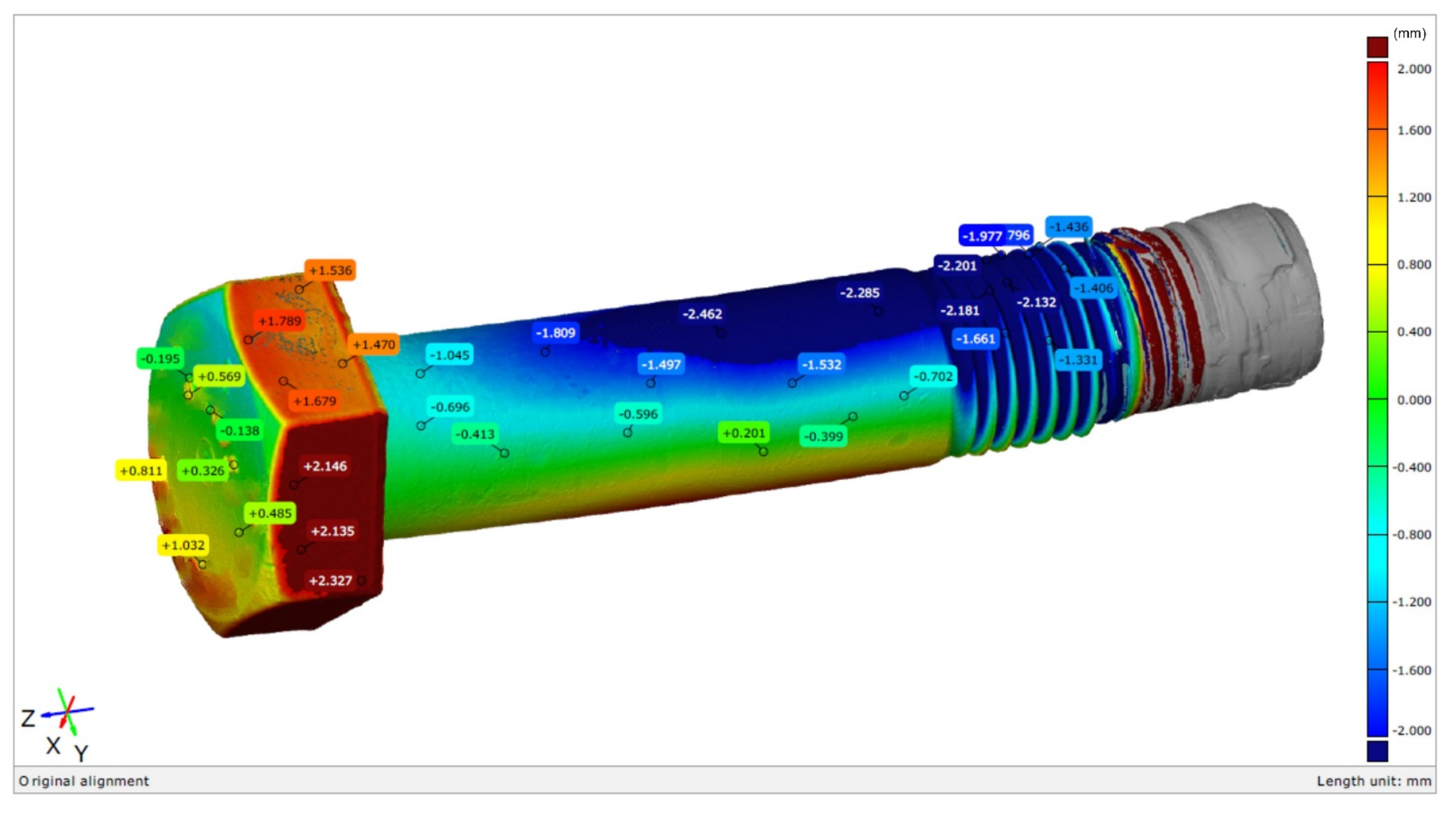
- The measurements of geometry were performed with the 3D GOM Atos Professional V7 SR2 optical scanner (GOM a Zeiss company, Braunschweig, Lower Saxony, Germany), and the obtained models were then compared with the CAD/CAM models of the new bolts with deviations from nominal dimensions according to the the PN EN ISO 898-1:2013-06 standard.
- The microscopic tests were performed using the Leica M205 C stereoscopic microscope (Leica Microsystems, Wetzlar, Hesse, Germany), Leica DM6000 M metallographic microscope (Leica Microsystems, Wetzlar, Hesse, Germany), as well as the Phenom World ProX scanning electron microscope (Thermo Fisher Scientific, Waltham, MA, USA), equipped with EDX detector on the conventionally prepared metallographic specimens etched with 2% Nital solution.
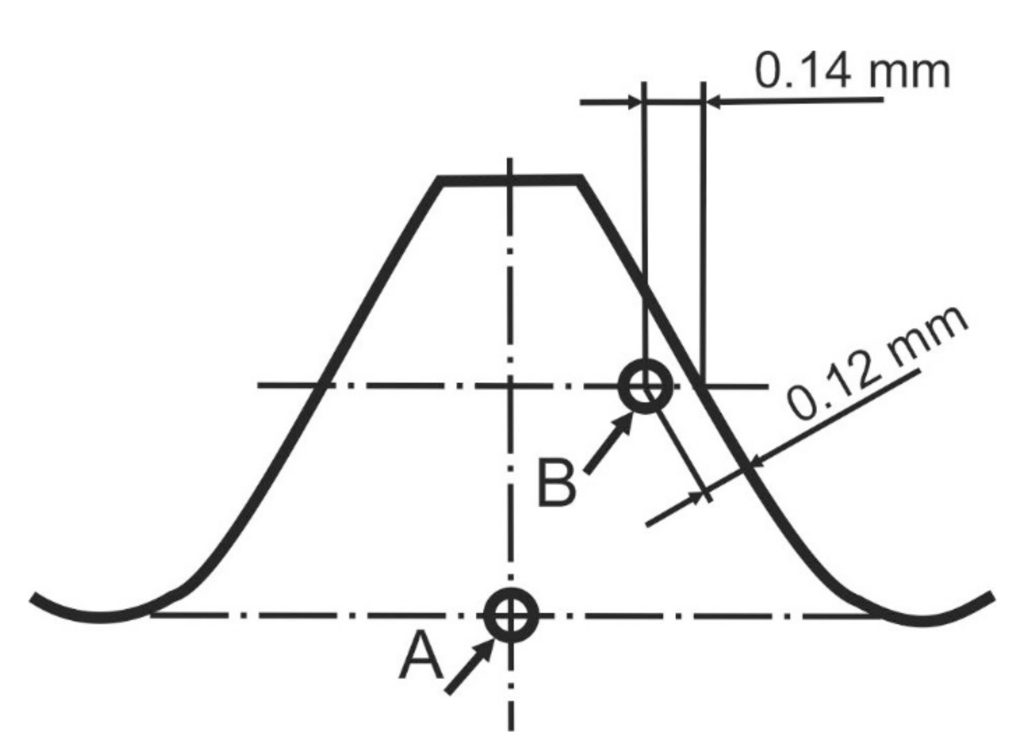
- The HV10 hardness measurements were performed using the Vickers method according to the PN-EN ISO 6507-1:2007 standard with the application of a 10 kg load. The test was performed using the Zwick Roell ZHU 8187.5 LKV hardness measuring machine (ZwickRoell, Ulm, Baden-Württemberg, Germany).
- The HV0.3 micro hardness measurements were performed using the Vickers method according to the PN-EN ISO 6507-1:2007 standard with the application of a 0.3 kg load. The measurements were performed using the Leco LM-248AT micro hardness machine (Leco Corporation, St. Joseph, MI, USA) and the AMH 43 system (Leco Corporation, St. Joseph, MI, USA).
- The chemical composition was determined by means of the spectral method using the GDS-500A analyser with glow discharge (Leco Corporation, St. Joseph, MI, USA).
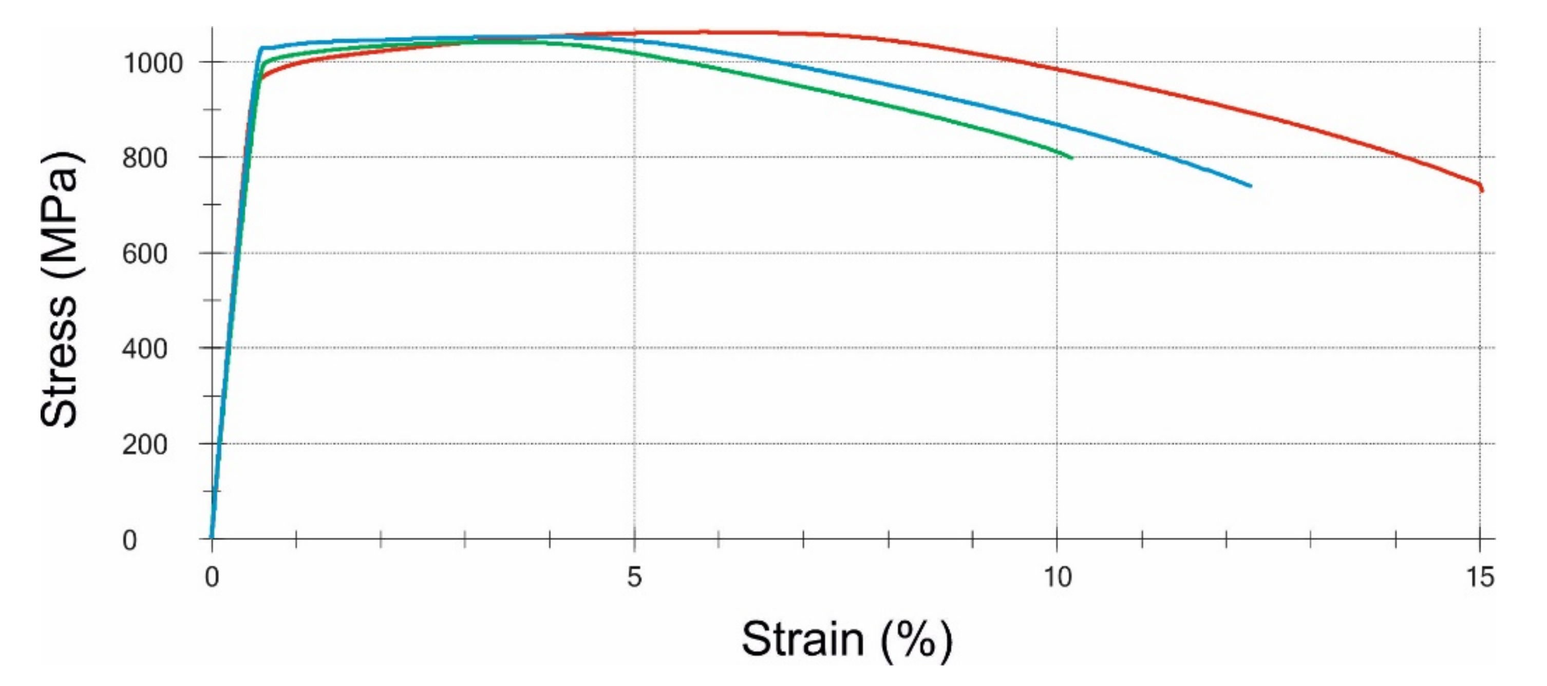
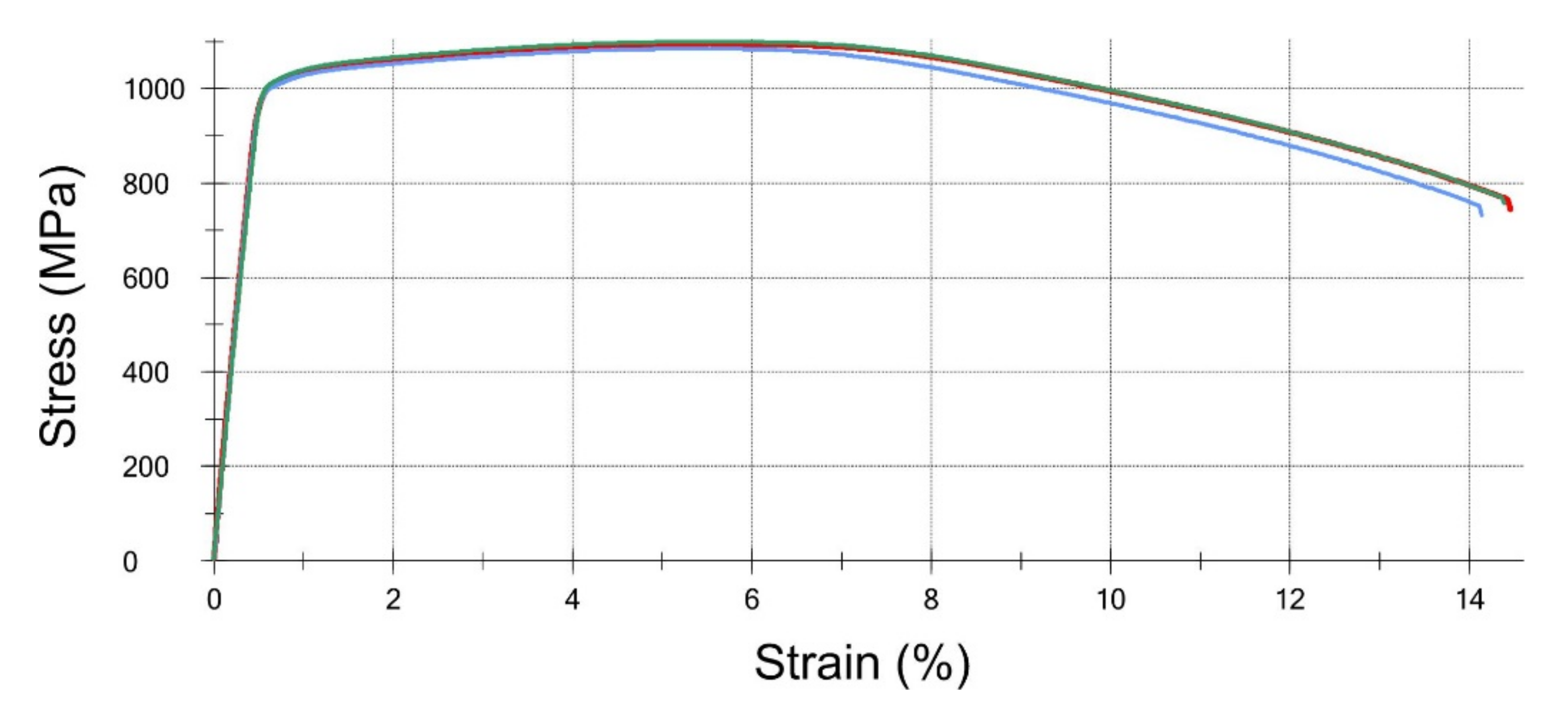
- The static tensile test was performed at room temperature according to the B30 method from the PN-EN ISO 6892-1:2010 standard. The test was performed using the Zwick-Roell Z100 THW (ZwickRoell, Ulm, Baden-Württemberg, Germany) strength testing machine equipped with the automatic extensometer makroXtens® II (ZwickRoell, Ulm, Baden-Württemberg, Germany).
- The impact resistance test was performed at a temperature of −20 °C according to the PN-EN ISO 148-1:2017-02 standard. The impact energy tests were carried out on non-standard Charpy V type test pieces and performed using the Zwick-Roell RKP 450 181616/2008 impact hammer (ZwickRoell, Ulm, Baden-Württemberg, Germany).
- The analysis of the deposit, using the method of atomic absorption spectroscopy according to the PN-EN ISO 15586:2005 standard, was performed with the use of the Perkin Elmer model Analyst 600 atomic absorption spectrometer (PerkinElmer, Waltham, MA, USA).
3. Research and Discussion
3.1. Chemical Analysis
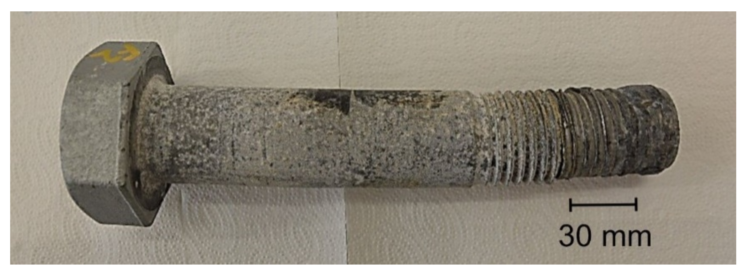
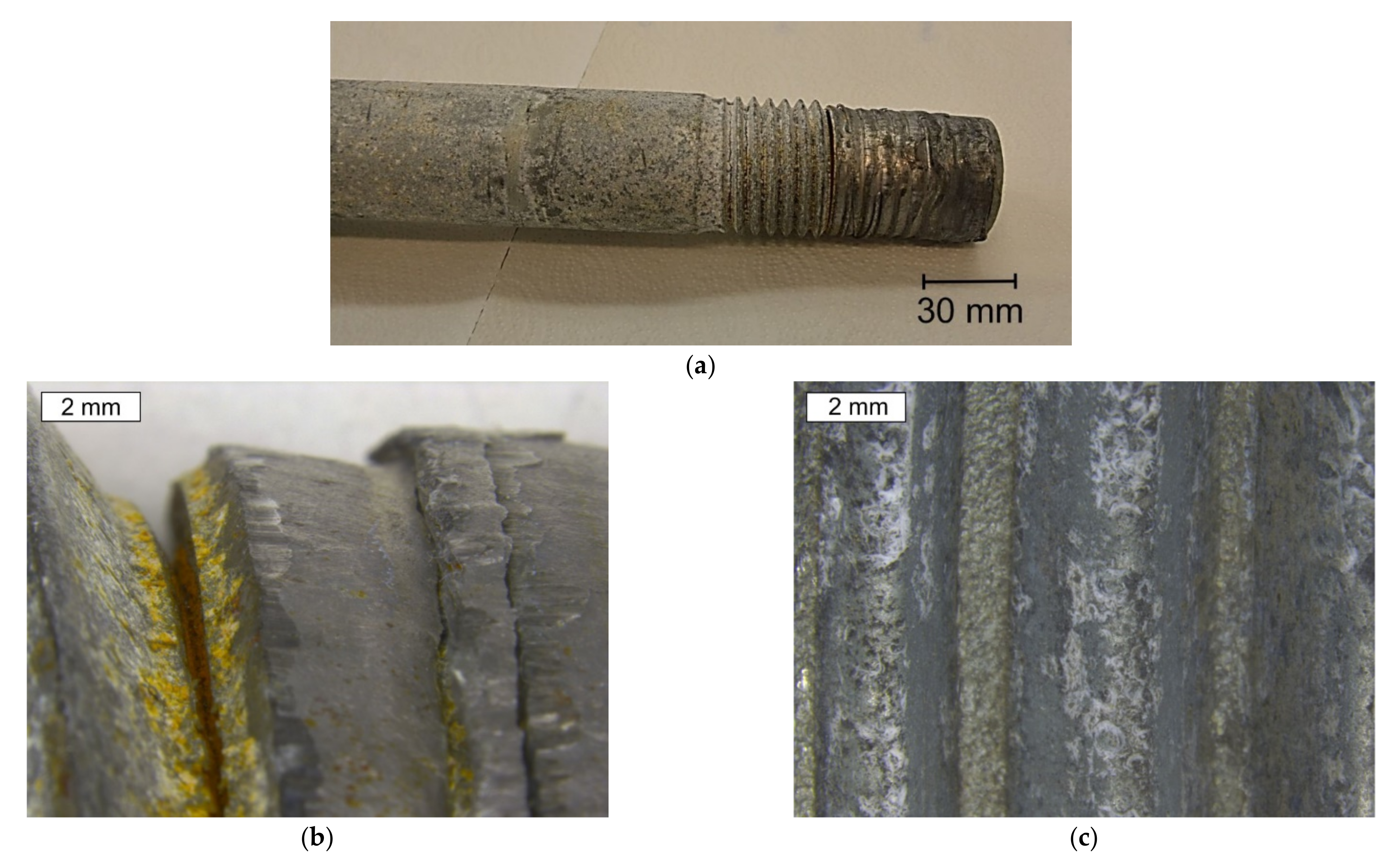
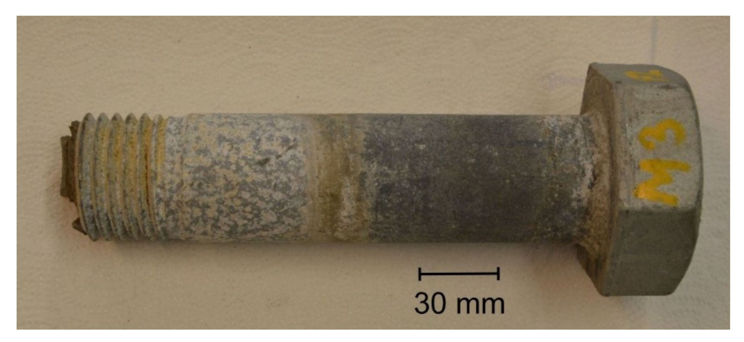
3.2. Macroscopic Examination
Bolt 1
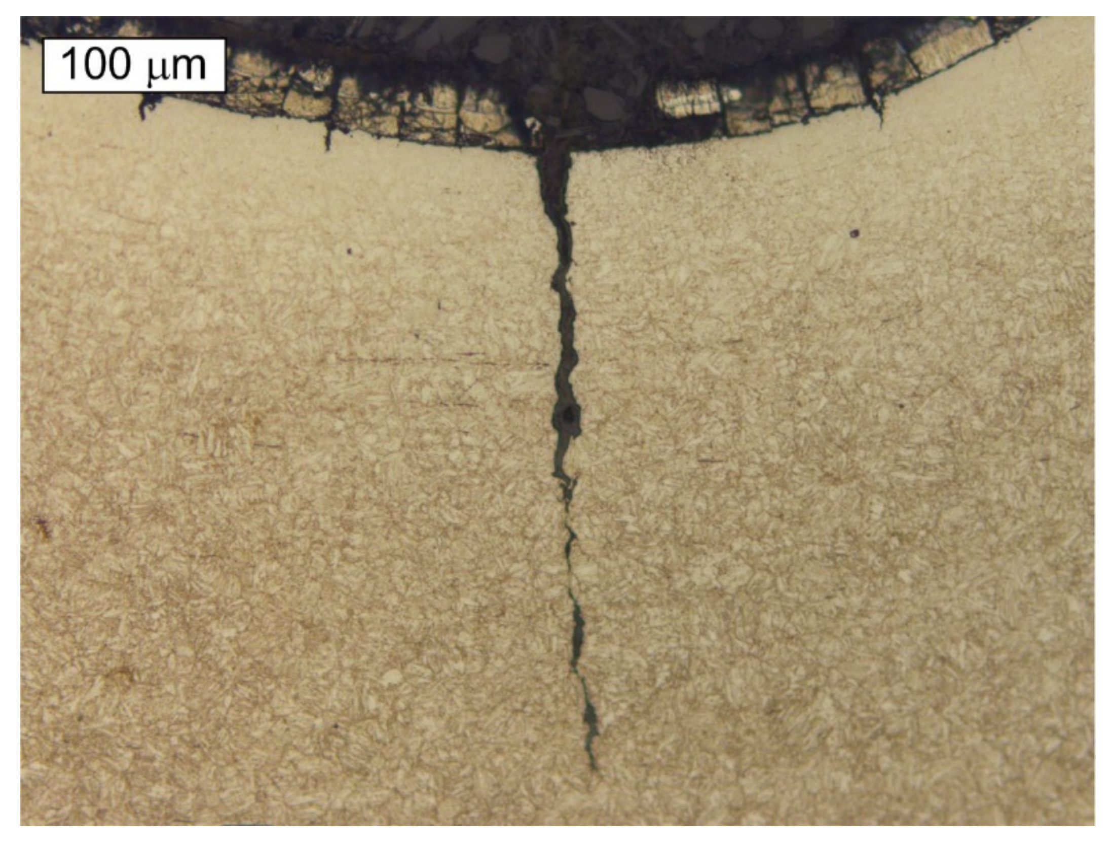
3.3. Microstructure Observations
3.3.1. Bolt 1
3.3.2. Bolt 2
3.4. Mechanical Properties
3.4.1. Tensile Strength
3.4.2. Hardness Measurements
3.4.3. Impact Strength
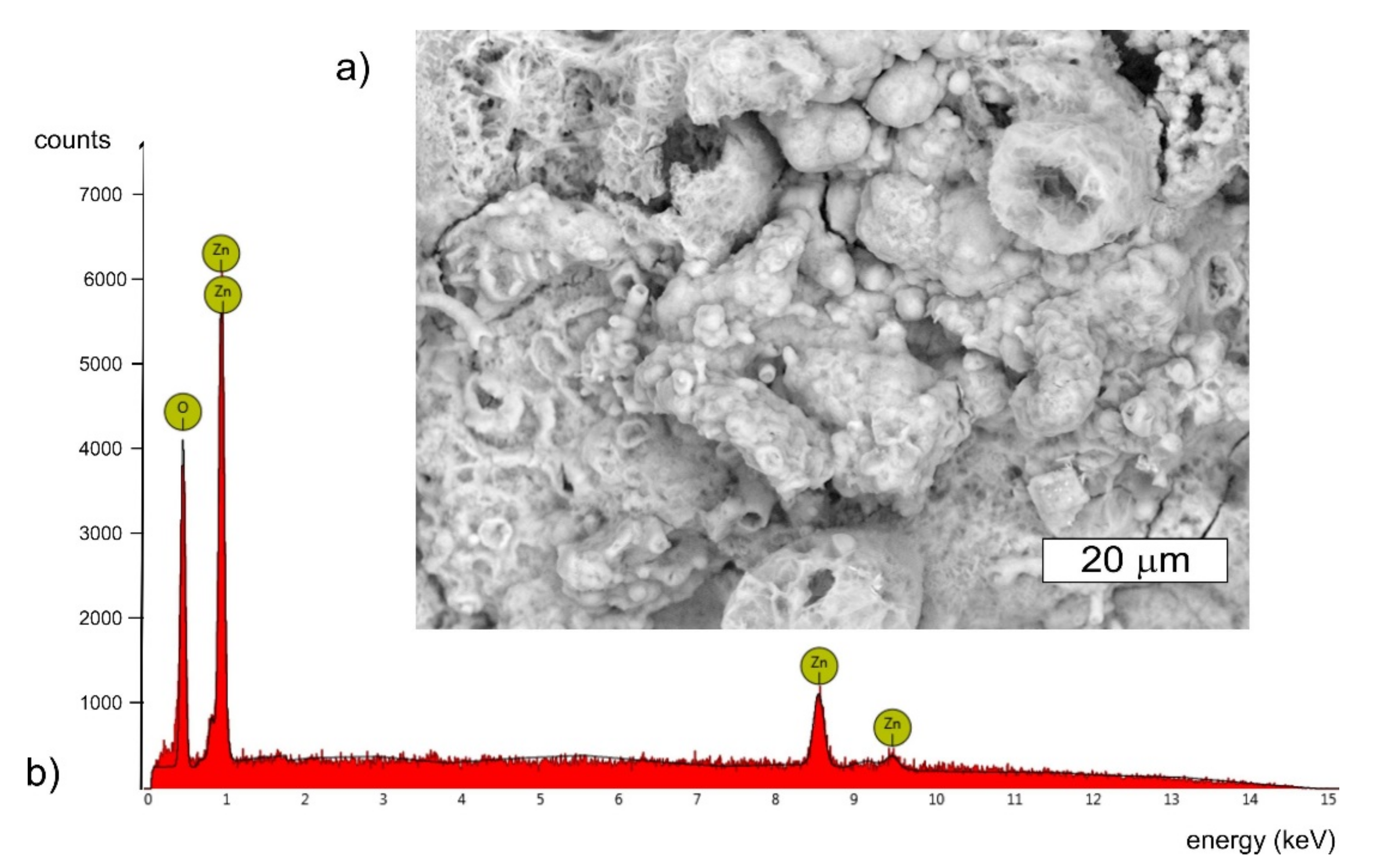
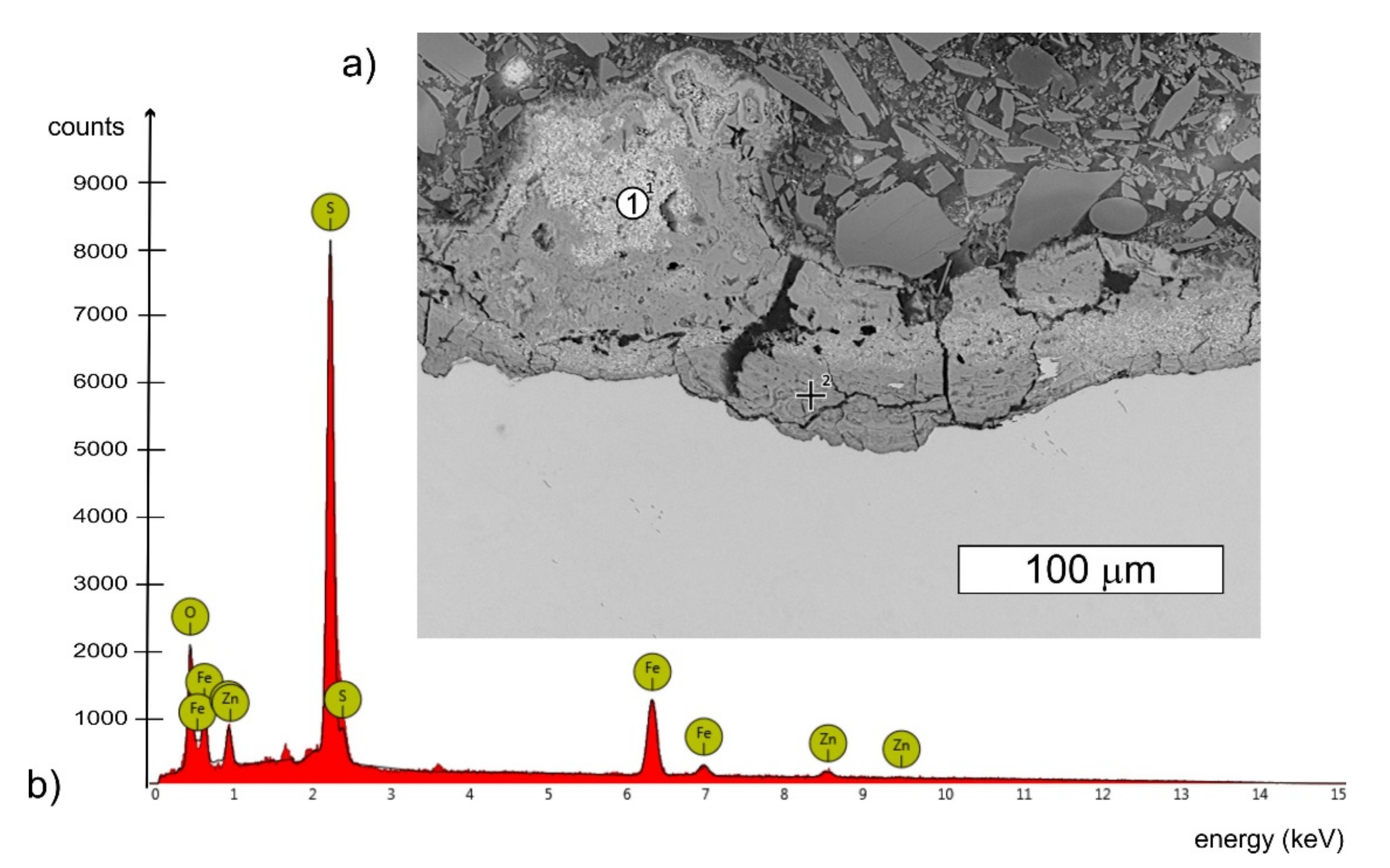
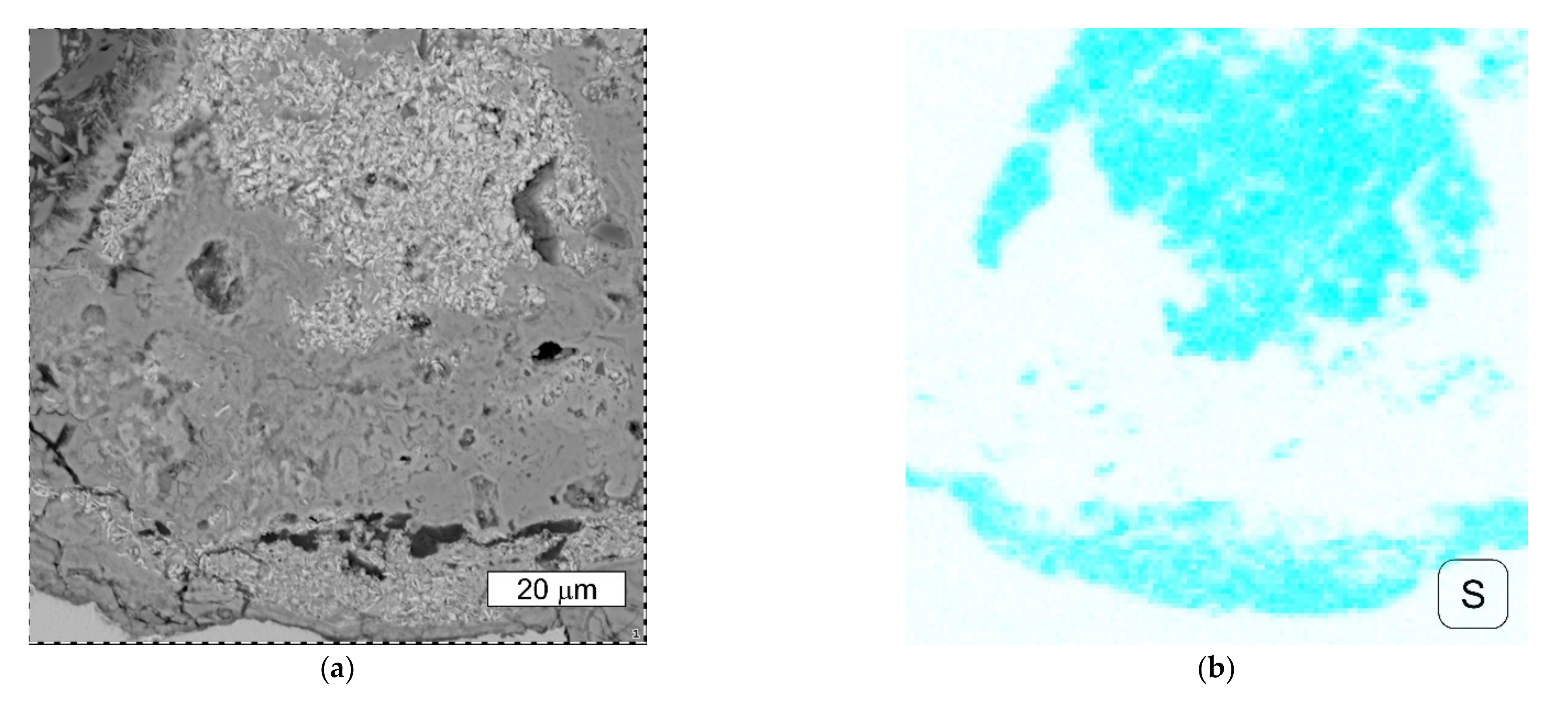
3.5. Analysis of Deposits on the Surface
4. Summary
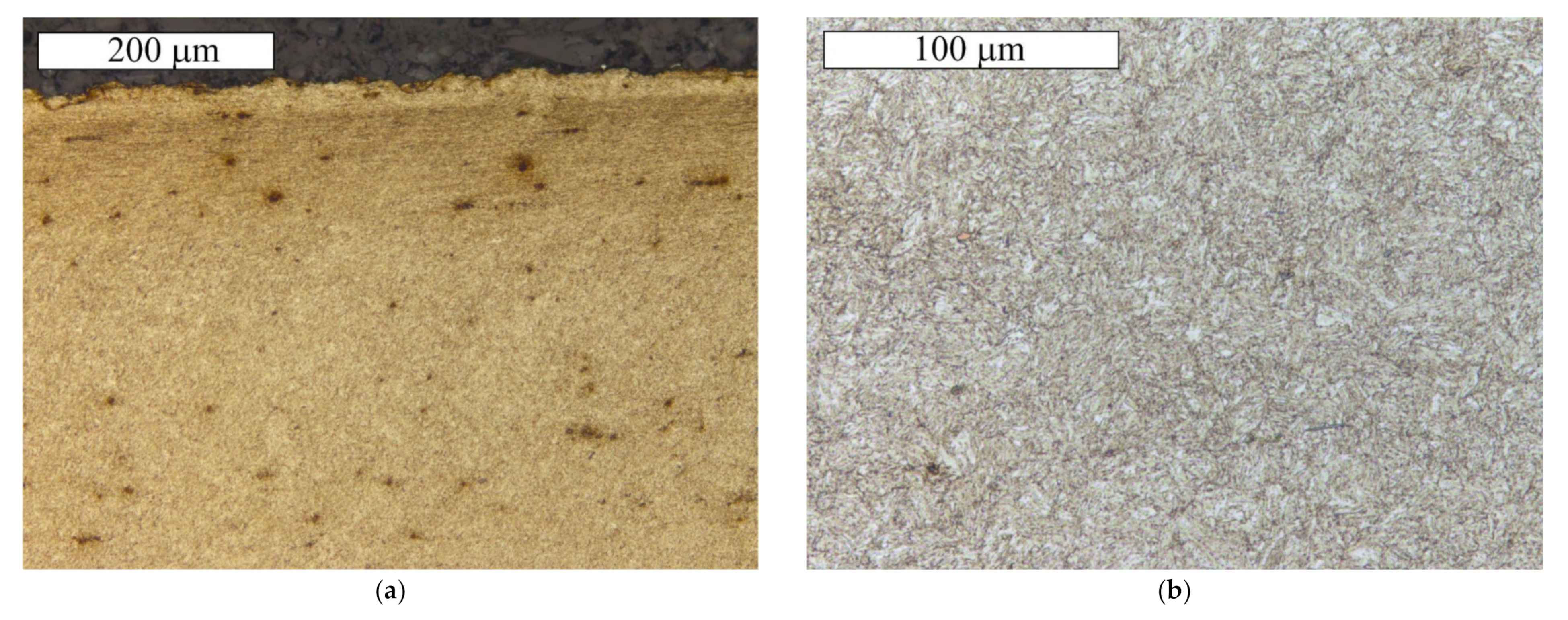
- The material of the tested bolts met all the quality criteria of the PN EN ISO 898-1:2013-06 standard. All the mechanical properties correspond to the specifications of this standard. Microscopic examinations revealed that the microstructure of the material of both the bolts was typical for tempering martensitic steel. The material properties were not the cause of bolt failure.
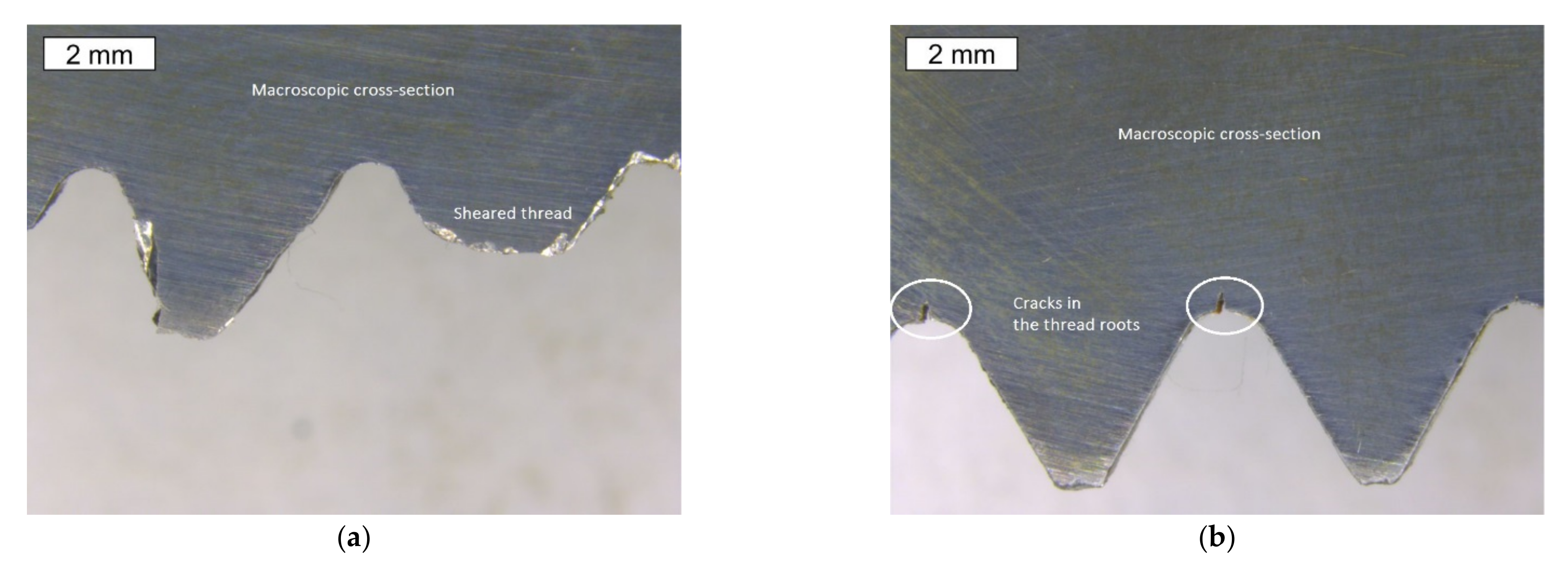
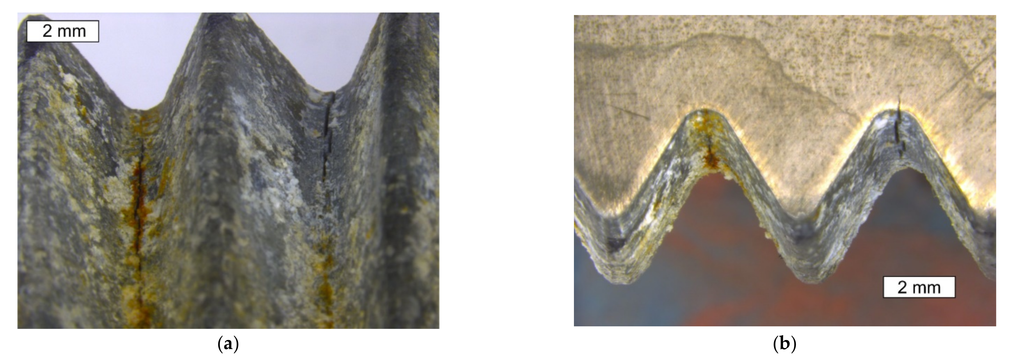
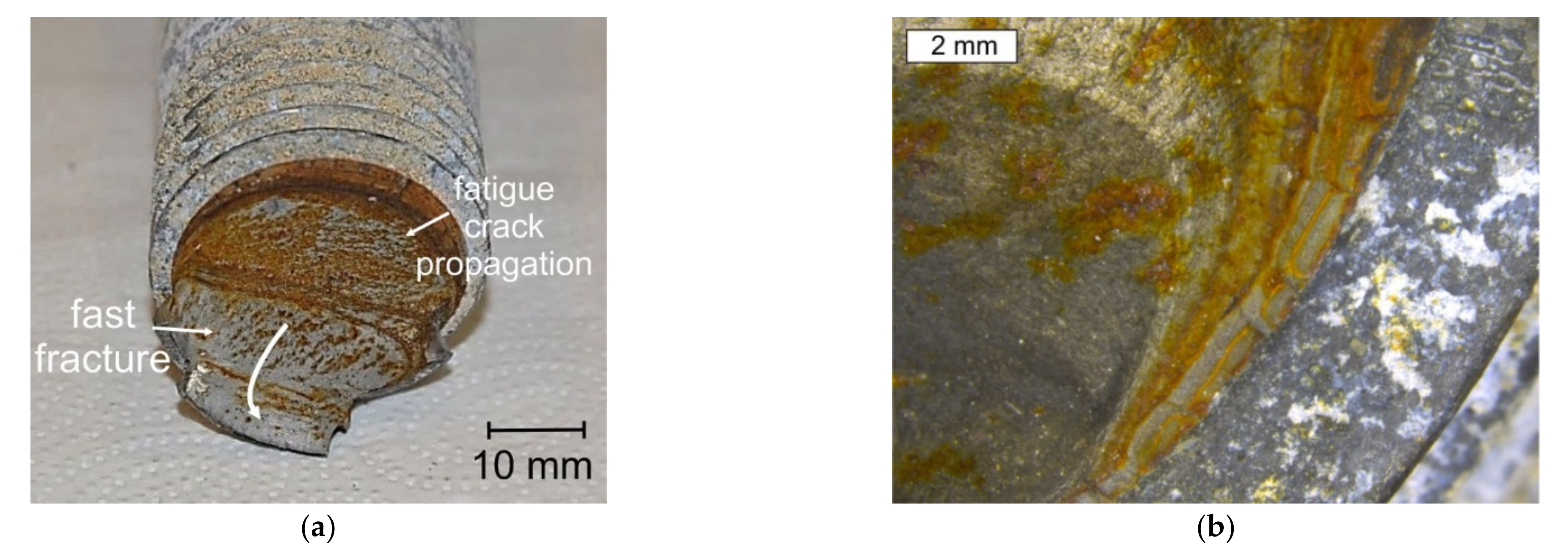
- The bolts, besides fractures and deformations, had deep cracks in their thread roots located in the area below the nut. In the parts of the threads bolted into the nuts, cracks in the thread roots were not observed. Numerous cracks of the bolts appearing in the thread roots outside the nut indicate that the bolts were fatigue cracked. The occurrence of many cracks in each of the bolts is a sign of strong fatigue loading and, possibly, unspecified oscillations of the bolts. The initial cracks then grew subcritically until they reached their critical size. The probable cause of failure could also be a preload less than the recommended one, which could lead to self-loosening of the joint. The corrosion, due to the applied torque, may have reduced the preload in the bolt.
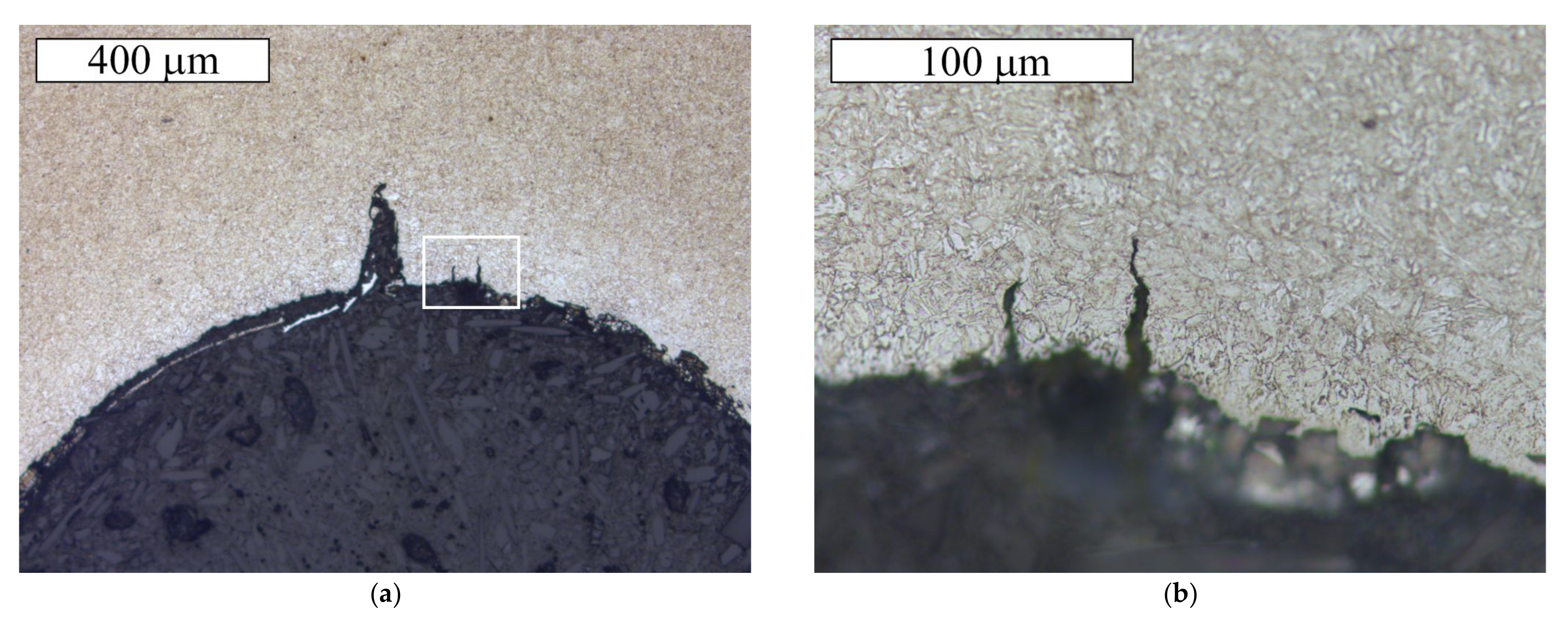
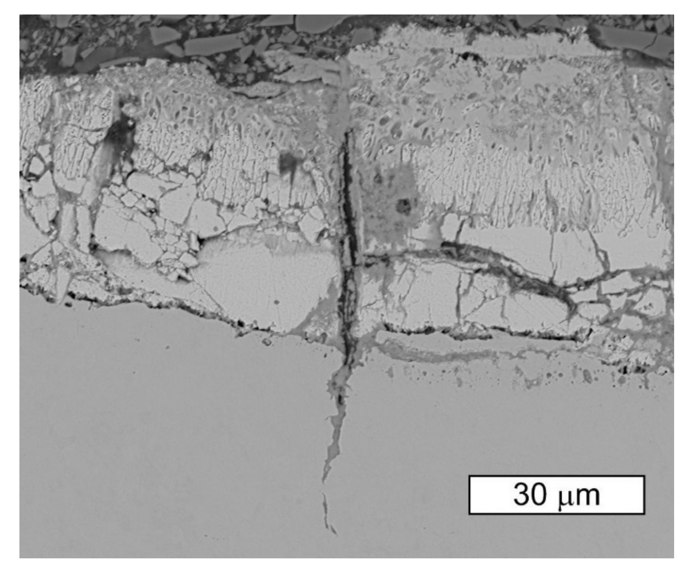
- During microscopic examinations of the zinc coatings, it was found that numerous radial cracks appear in them (perpendicular to the surface). Their presence in the coatings is not harmful because they do not lower the coating’s adhesion. Moreover, they do not deteriorate the corrosion resistance of the element, because when its surface is wet, zinc becomes a protective anode and iron enters the state of immunity. Steel substrate does not corrode even when moisture penetrates to the substrate. This principle works in the case of most of the radial cracks observed on the bolts. Observations of cracks in the zinc coating appearing at the lateral surfaces of the bolt threads allow for the statement that, in these places, the corrosion of the steel substrate, which is cathodically protected by the zinc coating, did not occur. Similar cracks were observed in the bolt thread roots, however, in these locations the appearance of steel substrate cracks filled with corrosion products was also observed. It cannot be ruled out that hydrogen plays an important role in further crack propagation. However, this is not the only factor. It can therefore be concluded that the internal stresses in the bolts are the additional factor that contributes to the propagation of cracks in the steel substrate. The mechanical factor concerning the development of cracks may be additionally intensified by the fatigue loads. There is also a theory that corrosion products play the role of the wedge-force in the loading process. This contributes to the opening of cracks that then become channels for the transfer of corrosive media.
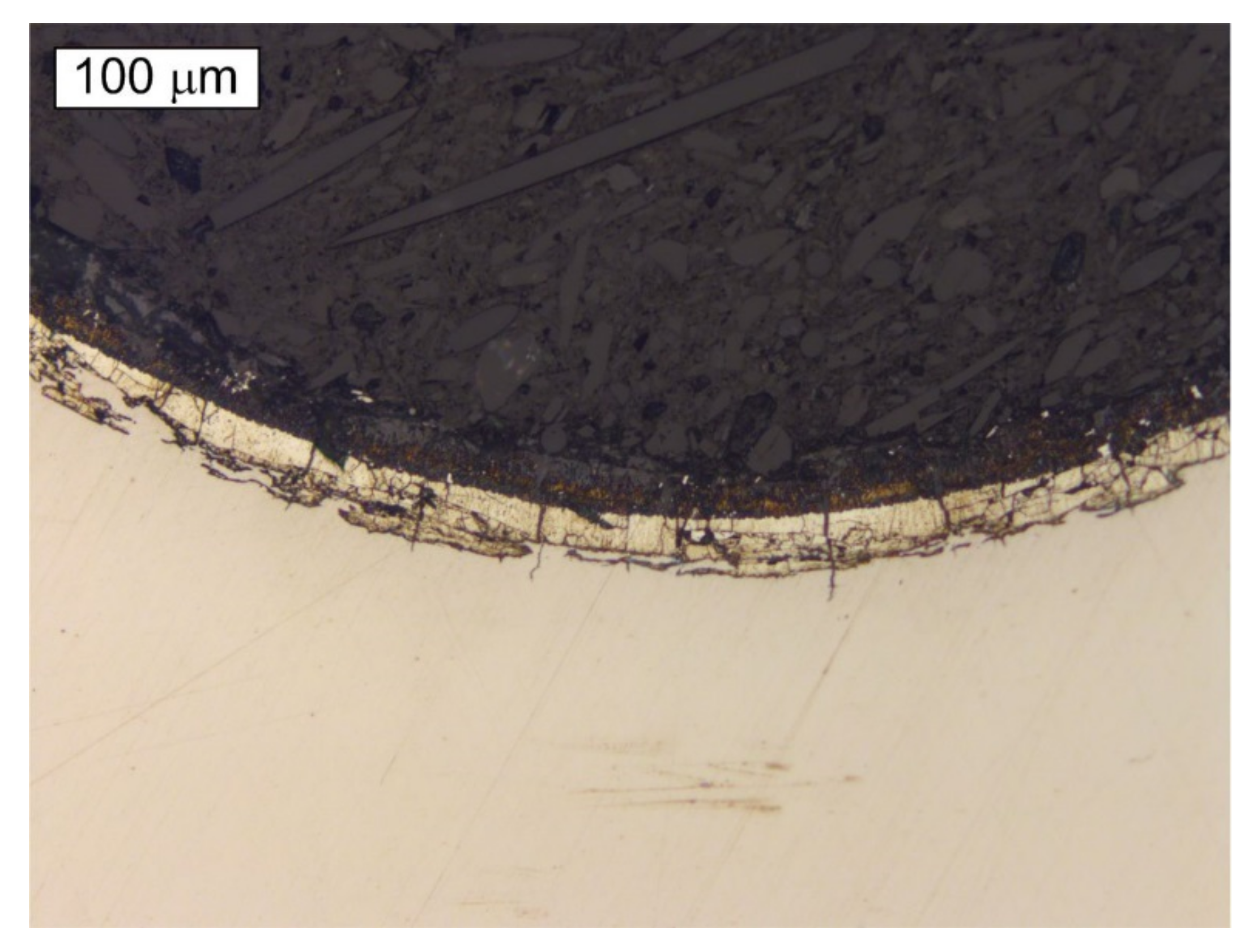
- The bolt was subjected to fatigue load, which induced a fatigue crack at the thread’s root that propagated towards the centre and caused the failure. Both the bolt shanks and the threaded parts of the bolts showed symptoms of strong white corrosion of their zinc layer. However, the heads of the bolts and the threaded part protruding from the nut were free of corrosion symptoms. This means that corrosion is favored by the oxygen concentration cell (differential aeration). Under these conditions, the areas where oxygen starvation occurs are anodic, while the areas with free access to oxygen are cathodic.
5. Conclusions
Author Contributions
Funding
Institutional Review Board Statement
Informed Consent Statement
Data Availability Statement
Conflicts of Interest
References
- Badrkhani Ajaei, B.; Soyoz, S. Effects of preload deficiency on fatigue demands of wind turbine tower bolts. J. Constr. Steel Res. 2020, 166, 105933. [Google Scholar] [CrossRef]
- Chou, J.S.; Tu, W.T. Failure analysis and risk management of a collapsed large wind turbine tower. Eng. Fail. Anal. 2011, 18, 295–313. [Google Scholar] [CrossRef]
- Lin, Y.; Tu, L.; Liu, H.; Li, W. Fault analysis of wind turbines in China. Renew. Sustain. Energy Rev. 2016, 55, 482–490. [Google Scholar] [CrossRef]
- Alonso-Martinez, M.; Adam, J.M.; Alvarez-Rabanal, F.P.; del Coz Díaz, J.J. Wind turbine tower collapse due to flange failure: FEM and DOE analyses. Eng. Fail. Anal. 2019, 104, 932–949. [Google Scholar] [CrossRef]
- Jiang, Z.; Hu, W.; Dong, W.; Gao, Z.; Ren, Z. Structural Reliability Analysis of Wind Turbines: A Review. Energies 2017, 10, 2099. [Google Scholar] [CrossRef]
- Casanova, F.; Mantilla, C. Fatigue failure of the bolts connecting a Francis turbine with the shaft. Eng. Fail. Anal. 2018, 90, 1–13. [Google Scholar] [CrossRef]
- Liu, J.; Ouyang, H.; Peng, J.; Zhang, C.; Zhou, P.; Ma, L.; Zhu, M. Experimental and numerical studies of bolted joints subjected to axial excitation. Wear 2016, 346–347, 66–77. [Google Scholar] [CrossRef]
- Shen, X.; Lu, L.; Zeng, D. Fatigue failure analysis of high strength bolts used for high-speed railway vehicle braking discs. Eng. Fail. Anal. 2020, 115, 104661. [Google Scholar] [CrossRef]
- Wang, H.-l.; Qin, S.-f. High-strength bolt corrosion fatigue life model and application. Sci. World J. 2014, 2014, 567318. [Google Scholar]
- Zampieri, P.; Curtarello, A.; Maiorana, E.; Pellegrino, C.; De Rossi, N.; Savio, G.; Concheri, G. Influence of corrosion morphology on the fatigue strength of bolted joints. Proc. Struct. Integr. 2017, 5, 409–415. [Google Scholar] [CrossRef]
- Álvarez, J.A.; Lacalle, R.; Arroyo, B.; Cicero, S.; Gutiérrez-Solana, F. Failure analysis of high strength galvanized bolts used in steel towers. Metals 2016, 6, 163. [Google Scholar] [CrossRef]
- Yu, V.Y.; Kohl, J.G.; Crapanzano, R.A.; Davies, M.W.; Elam, A.G.; Veach, M.K. Failure analysis of the M16 rifle bolt. Eng. Fail. Anal. 2005, 12, 746–754. [Google Scholar] [CrossRef]
- Esaklul, K.A.; Ahmed, T.M. Prevention of failures of high strength fasteners in use in offshore and subsea applications. Eng. Fail. Anal. 2009, 16, 1195–1202. [Google Scholar] [CrossRef]
- Milan, M.T.; Spinelli, D.; Bose Filho, W.W.; Montezuma, M.F.V.; Tita, V. Failure analysis of a SAE 4340 steel locking bolt. Eng. Fail. Anal. 2004, 11, 915–924. [Google Scholar] [CrossRef]
- Shen, X.; Lu, L.; Zeng, D.; Zhang, M. Improving fatigue resistance of high strength bolt under cyclic transverse loading by fine particle peening. Eng. Struct. 2020, 210, 110359. [Google Scholar] [CrossRef]
- Berto, F.; Fergani, O. Fatigue behaviour of welded structural steel subjected to hot-dip galvanization process. Int. J. Fatigue 2017, 101, 439–447. [Google Scholar] [CrossRef]
- Berto, F.; Mutignani, F.; Guido, E. Effect of hot dip galvanization on the fatigue behaviour of steel bolted connections. Int. J. Fatigue 2016, 93, 168–172. [Google Scholar] [CrossRef]
- Berto, F.; Razavi, S.M.J.; Ayatollahi, M.R.; Mutignani, F. Mechanical behavior of hot-dip galvanized welded steel under cyclic loading. Proc. Struct. Integr. 2017, 3, 135–143. [Google Scholar] [CrossRef]
- Berchem, K.; Hocking, M.G. The influence of pre-straining on the corrosion fatigue performance of two hot-dip galvanised steels. Corros. Sci. 2006, 48, 4094–4112. [Google Scholar] [CrossRef]
- Berto, F.; Razavi, S.M.J.; Ayatollahi, M.R.; Mutignani, F. Mechanical behaviour of hot dip galvanized steel connection under cyclic loading. Proc. Struct. Integr. 2017, 3, 77–84. [Google Scholar] [CrossRef]
- Berto, F.; Mutignani, F.; Pittarello, L. Effect of hot-dip galvanization on the fatigue behaviour of welded structural steel. Proc. Struct. Integr. 2016, 2, 1813–1820. [Google Scholar] [CrossRef]
- Michailidis, N.; Stergioudi, F.; Maliaris, G.; Tsouknidas, A. Influence of galvanization on the corrosion fatigue performance of high-strength steel. Surf. Coat. Technol. 2014, 259, 456–464. [Google Scholar] [CrossRef]
- Berchem, K.; Hocking, M.G. The influence of pre-straining on the high-cycle fatigue performance of two hot-dip galvanised car body steels. Mater. Charact. 2007, 58, 593–602. [Google Scholar] [CrossRef]
- Camurri, C.P.; Benavente, R.G.; Roa, I.S.; Carrasco, C.C. Deformation and fatigue behavior of hot dip galvanized coatings. Mater. Charact. 2005, 55, 203–210. [Google Scholar] [CrossRef]
- Wentzel, H.; Huang, X. Experimental characterization of the bending fatigue strength of threaded fasteners. Int. J. Fatigue 2015, 72, 102–108. [Google Scholar] [CrossRef]
- Zhao, H. Stress concentration factors within bolt-nut connectors under elasto-plastic deformation. Int. J. Fatigue 1998, 20, 651–659. [Google Scholar] [CrossRef]
- Volovitch, P.; Allely, C.; Ogle, K. Understanding corrosion via corrosion product characterization: I. Case study of the role of Mg alloying in Zn–Mg coating on steel. Corros. Sci. 2009, 51, 1251–1262. [Google Scholar] [CrossRef]
- Salgueiro Azevedo, M.; Allély, C.; Ogle, K.; Volovitch, P. Corrosion mechanisms of Zn(Mg, Al) coated steel: 2. The effect of Mg and Al alloying on the formation and properties of corrosion products in different electrolytes. Corros. Sci. 2015, 90, 482–490. [Google Scholar] [CrossRef]
- Zhang, X.; Leygraf, C.; Wallinder, I.O. Atmospheric corrosion of Galfan coatings on steel in chloride-rich environments. Corros. Sci. 2013, 73, 62–71. [Google Scholar] [CrossRef]
- Tang, N.; Liu, Y. Corrosion performance of aluminum-containing zinc coatings. ISIJ Int. 2010, 50, 455–462. [Google Scholar] [CrossRef][Green Version]
- Di Cocco, V.; Iacoviello, F.; D’Agostino, L.; Natali, S. Damage micromechanisms in a hot dip galvanized steel. Proc. Struct. Integr. 2017, 3, 231–236. [Google Scholar] [CrossRef]
- Di Cocco, V.; Iacoviello, F.; Natali, S. Damaging micromechanisms in hot-dip galvanizing Zn based coatings. Theor. App. Fract. Mech. 2014, 70, 91–98. [Google Scholar] [CrossRef]
- Ploypech, S.; Boonyongmaneerat, Y.; Jearanaisilawong, P. Crack initiation and propagation of galvanized coatings hot-dipped at 450 °C under bending loads. Surf. Coat. Technol. 2012, 206, 3758–3763. [Google Scholar] [CrossRef]
- Reumont, G.; Vogt, J.B.; Iost, A.; Foct, J. The effects of an Fe–Zn intermetallic-containing coating on the stress corrosion cracking behavior of a hot-dip galvanized steel. Surf. Coat. Technol. 2001, 139, 265–271. [Google Scholar] [CrossRef]
- Iacoviello, F.; Di Cocco, V.; Natali, S. Fatigue Damaging Mechanisms in a Hot-Dip Zinc Coated Steel. In Proceedings of the International Conference on Crack Paths (CP 2006), University of Parma, Parma, Italy, 14–16 September 2006. [Google Scholar]


| Symbol of the Element | C | Mn | Si | P | S | Cr | Cu | Mo | Ni | Al | Ti | V | B |
|---|---|---|---|---|---|---|---|---|---|---|---|---|---|
| Bolt S1 | 0.32 | 1.44 | 0.18 | 0.010 | 0.008 | 0.41 | 0.09 | 0.06 | 0.25 | 0.03 | 0.04 | <0.01 | 0.001 |
| Bolt S2 | 0.33 | 1.43 | 0.19 | 0.010 | 0.010 | 0.40 | 0.09 | 0.06 | 0.25 | 0.03 | 0.04 | <0.01 | 0.001 |
| Required for class 10.9 | 0.20–0.55 | – | – | max. 0.025 | max. 0.025 | min. 0.3 | – | min. 0.2 | min. 0.3 | – | – | Min. 0.1% | Max. 0.003 |
| Material Property | Proof Stress 0.2%, Rp0.2 (MPa) | Tensile Strength, Rm (MPa) | Elongation, A5.65 (%) | Reduction of Area, Z (%) |
|---|---|---|---|---|
| Bolt S1 | 1003 ± 29 | 1052 ± 10 | 12.1 ± 2.4 | 53.7 ± 3.5 |
| Bolt S2 | 1012 ± 6 | 1093 ± 8 | 13.9 ± 0.2 | 54.7 ± 2.0 |
| Required for class 10.9 | Min. 940 | Min. 1040 | Min. 9 | Min. 48 |
| Bolt Number | Hardness HV0.3 ± U | ||
|---|---|---|---|
| HV(A) | HV(B) | Surface Hardness | |
| S1 | 332.3 ± 23.70 | 324.3 ± 23.70 | 331.02 ± 26.01 |
| S2 | 342.5 ± 23.70 | 324.8 ± 23.70 | 343.08 ± 24.55 |
Publisher’s Note: MDPI stays neutral with regard to jurisdictional claims in published maps and institutional affiliations. |
© 2021 by the authors. Licensee MDPI, Basel, Switzerland. This article is an open access article distributed under the terms and conditions of the Creative Commons Attribution (CC BY) license (http://creativecommons.org/licenses/by/4.0/).
Share and Cite
Lachowicz, M.B.; Lachowicz, M.M. Influence of Corrosion on Fatigue of the Fastening Bolts. Materials 2021, 14, 1485. https://doi.org/10.3390/ma14061485
Lachowicz MB, Lachowicz MM. Influence of Corrosion on Fatigue of the Fastening Bolts. Materials. 2021; 14(6):1485. https://doi.org/10.3390/ma14061485
Chicago/Turabian StyleLachowicz, Maciej B., and Marzena M. Lachowicz. 2021. "Influence of Corrosion on Fatigue of the Fastening Bolts" Materials 14, no. 6: 1485. https://doi.org/10.3390/ma14061485
APA StyleLachowicz, M. B., & Lachowicz, M. M. (2021). Influence of Corrosion on Fatigue of the Fastening Bolts. Materials, 14(6), 1485. https://doi.org/10.3390/ma14061485