
Electrically Tunable Left-Handed Textile Metamaterial for Microwave Applications

 ,
,  ,
,  ,
,  , ,
, ,  ,
,  ,
, 
Abstract
1. Introduction
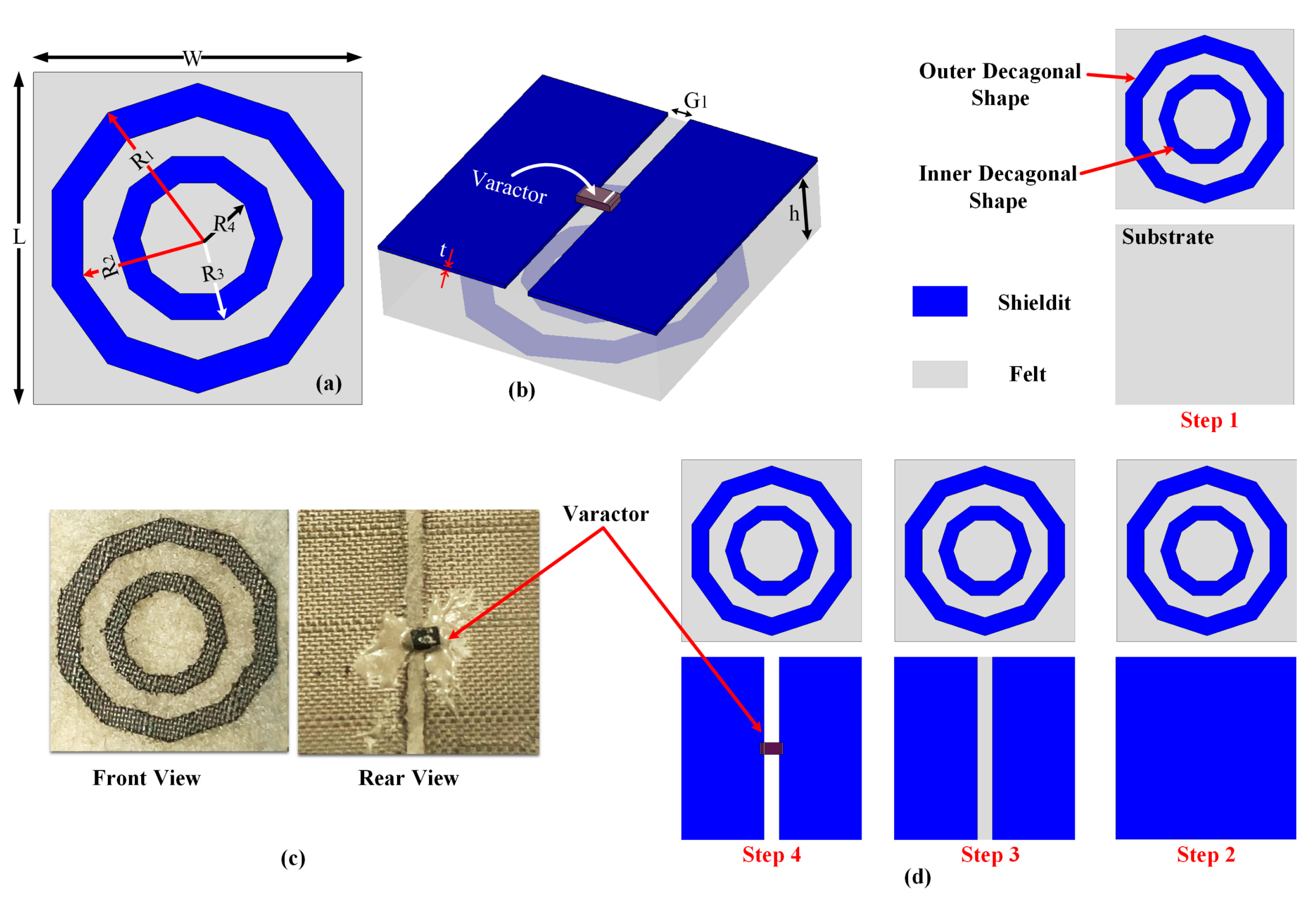
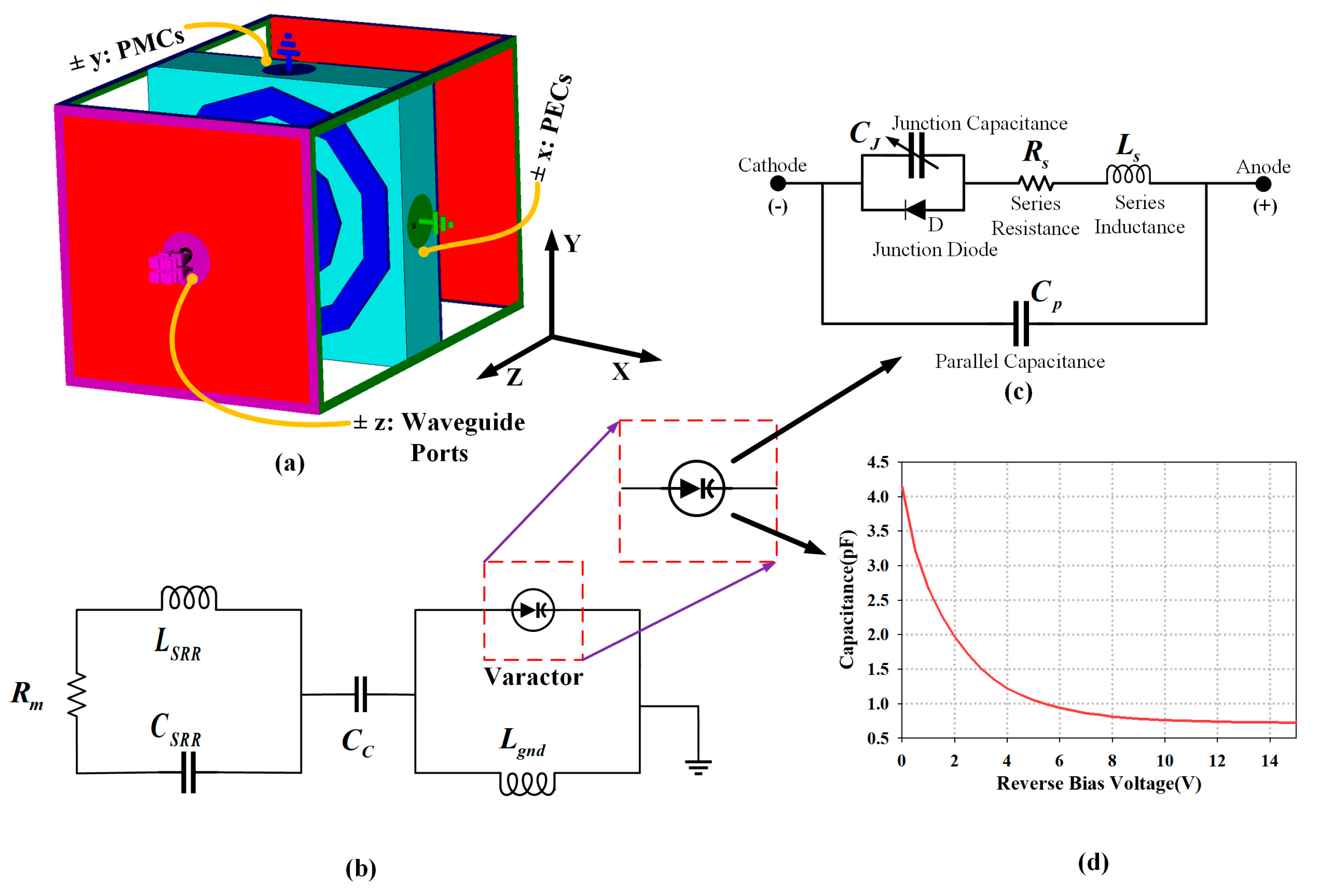
2. Tunable Metamaterial Unit Cell Design
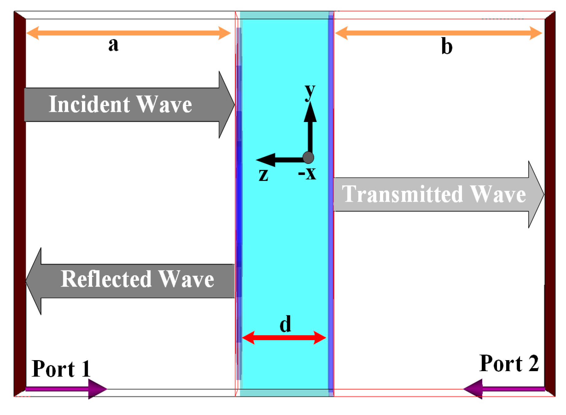
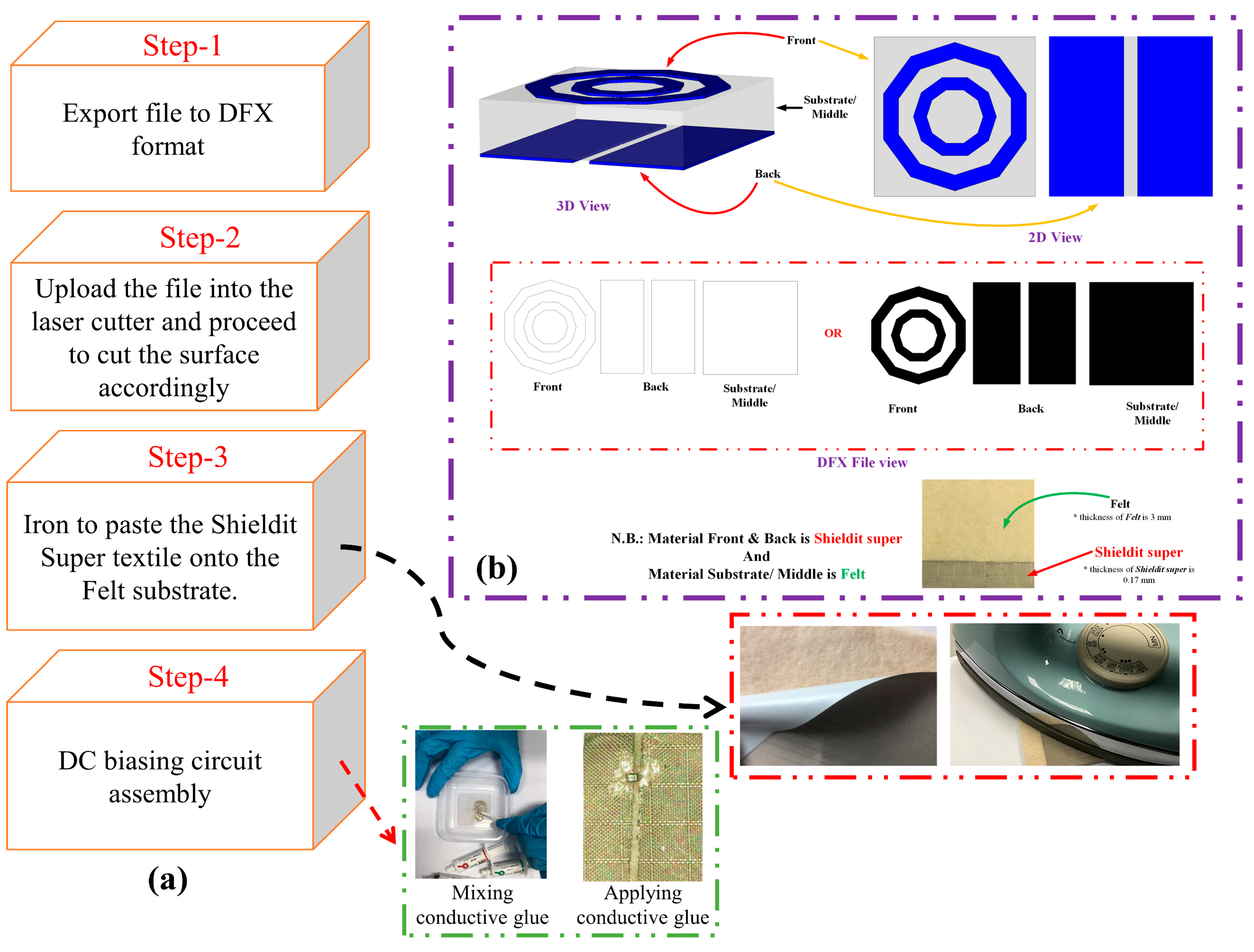
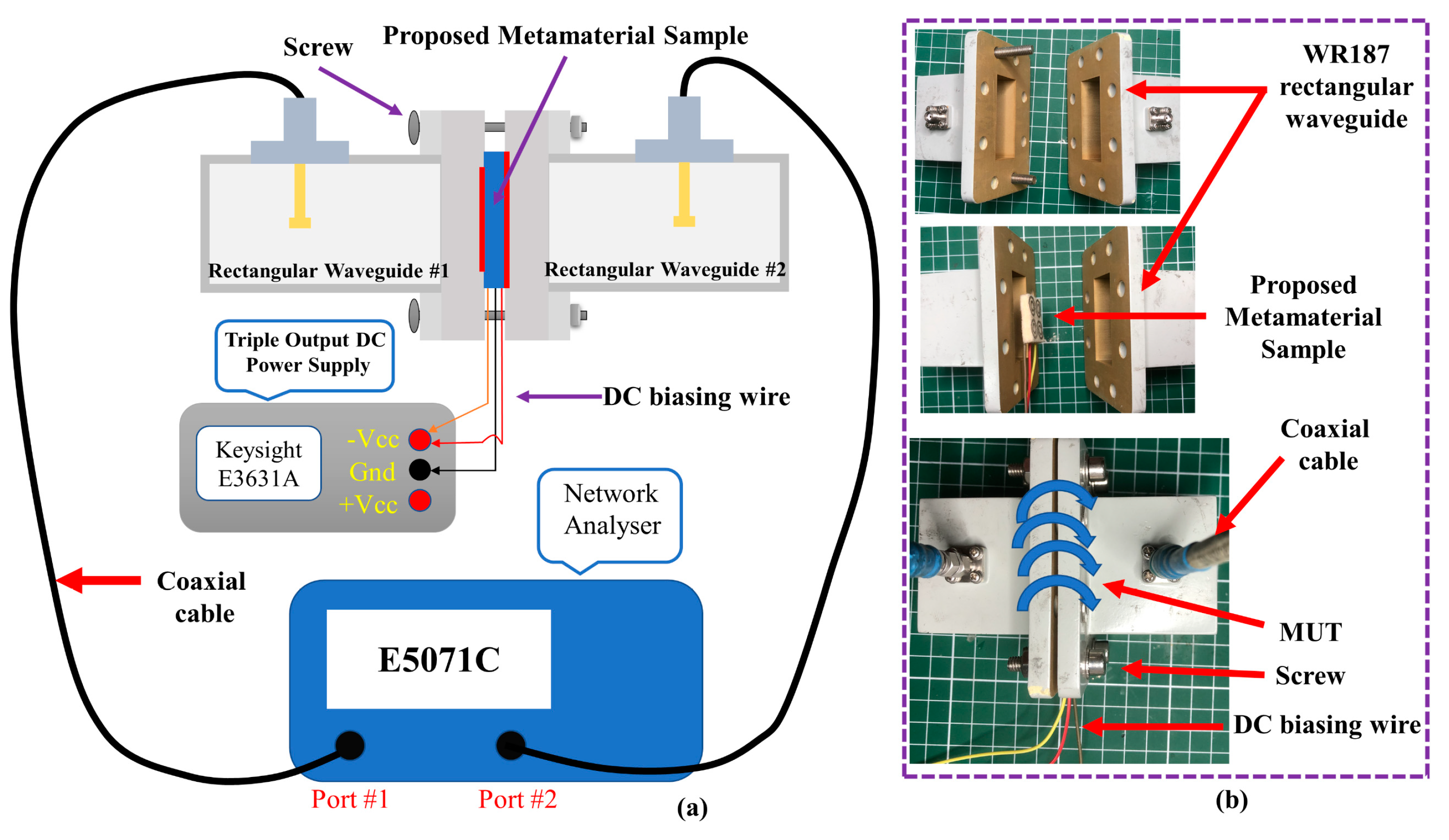
3. Methodology
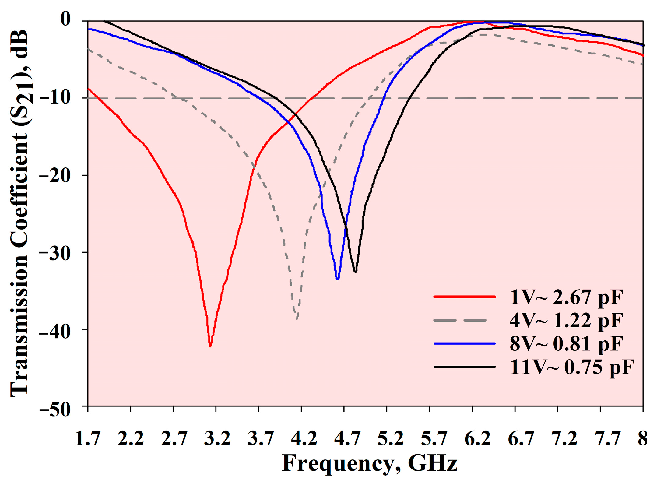
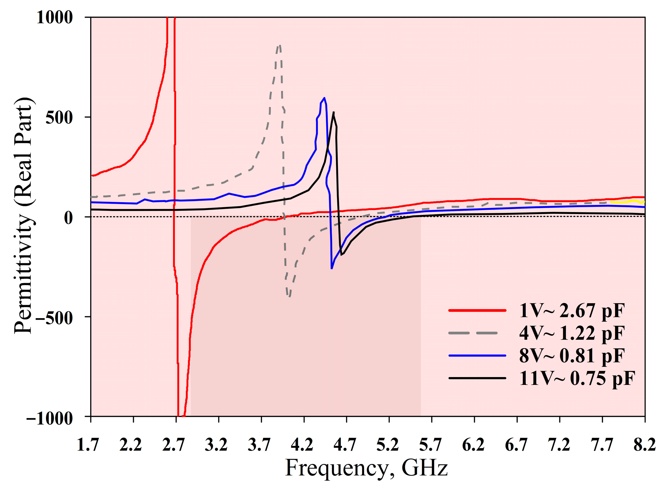
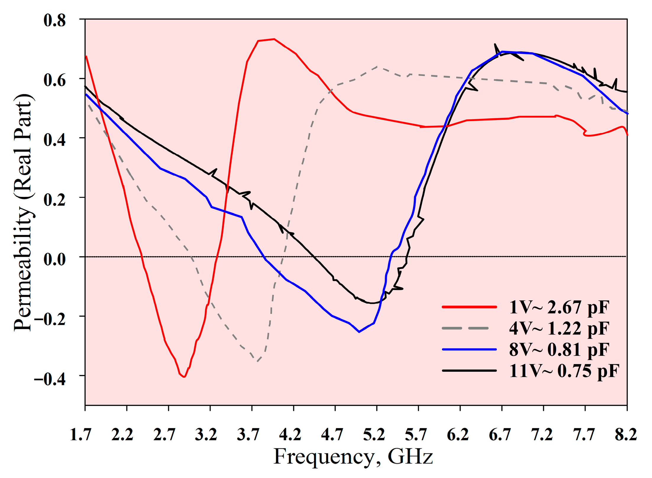
4. Results and Discussion
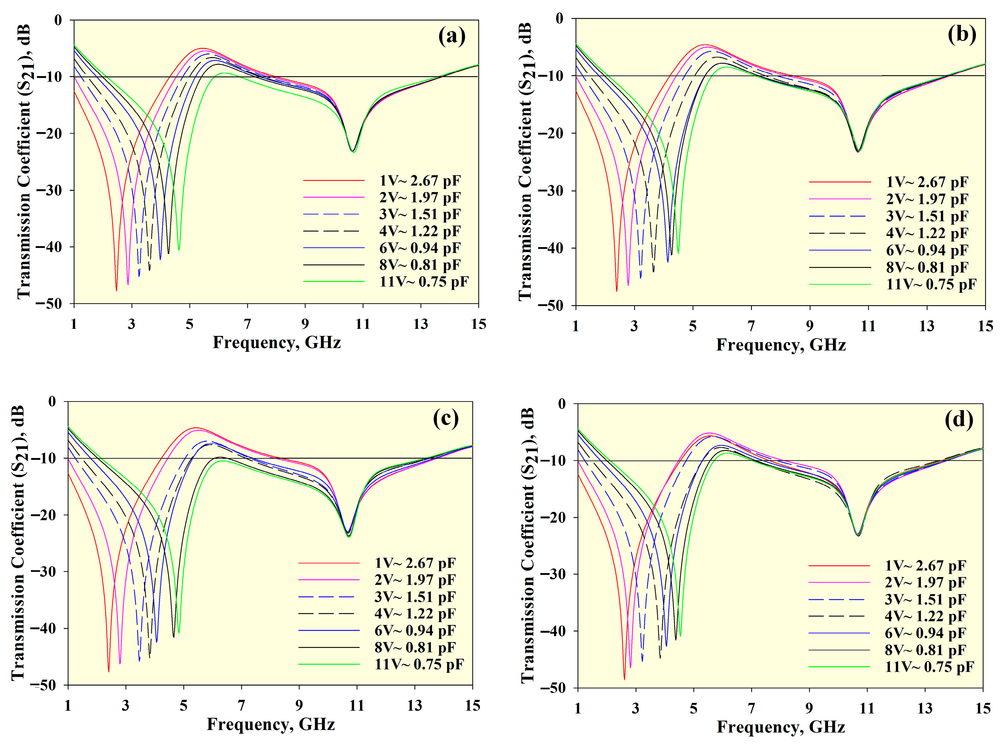
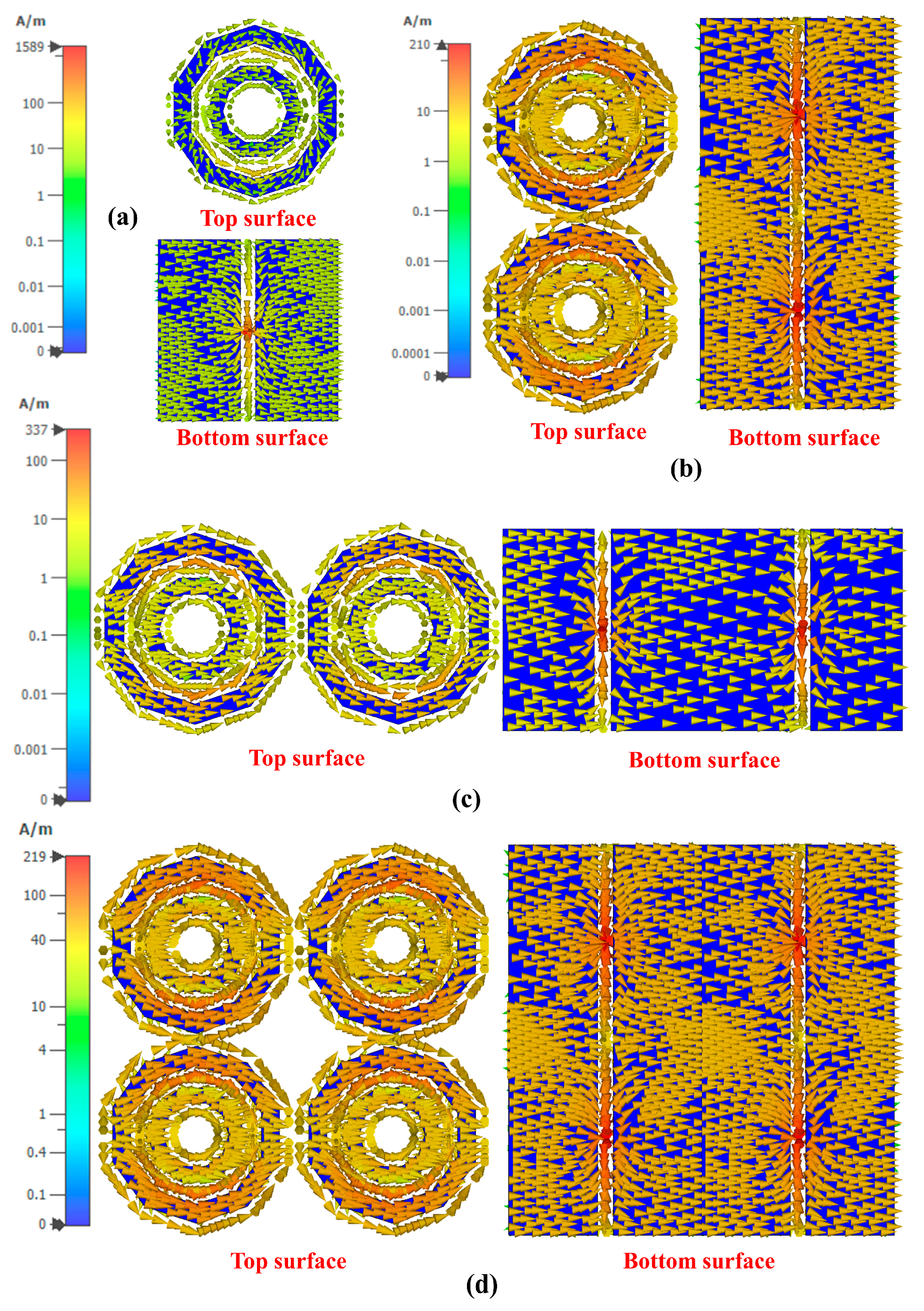
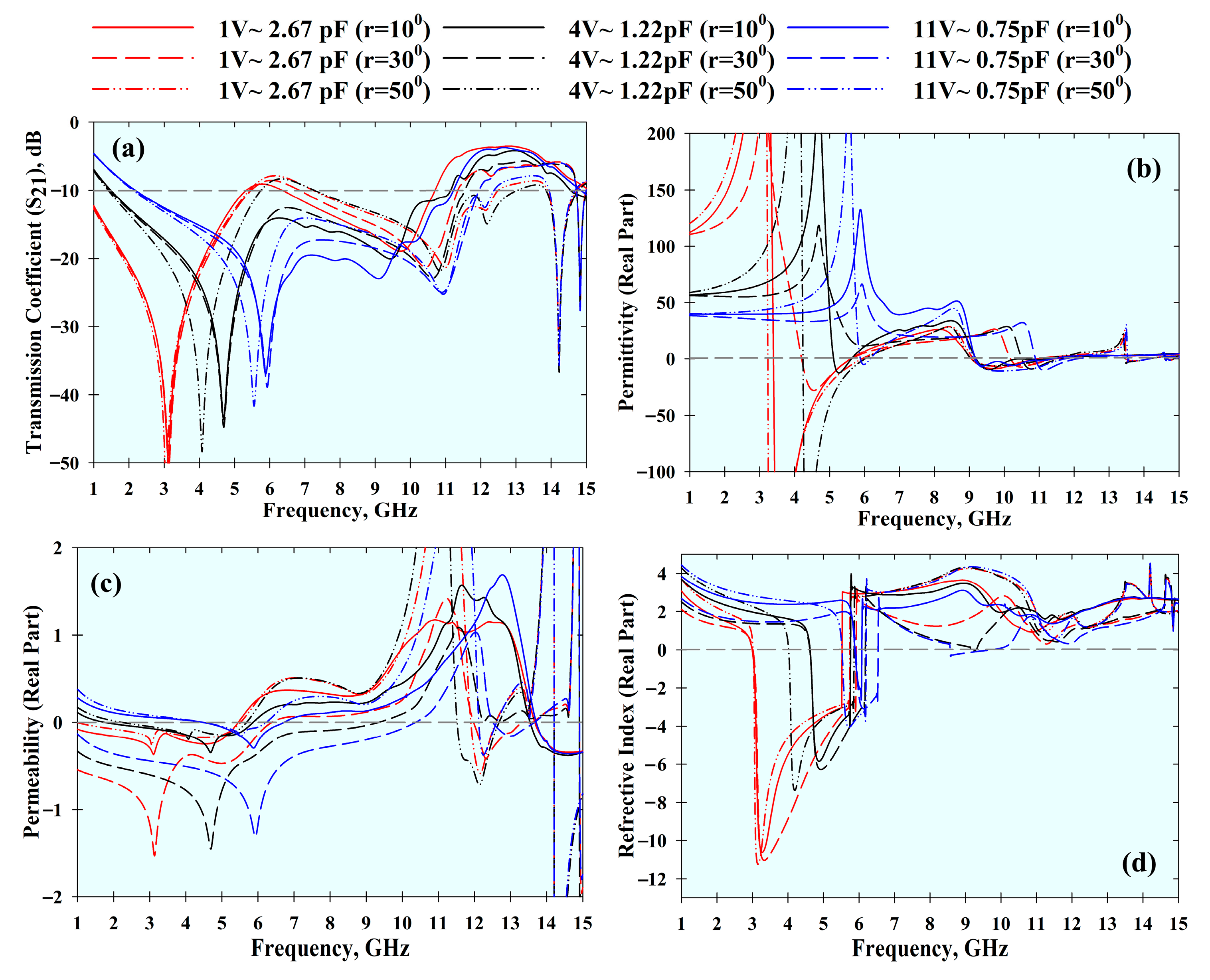
4.1. Modelling and Simulation
4.2. Deformation Analysis
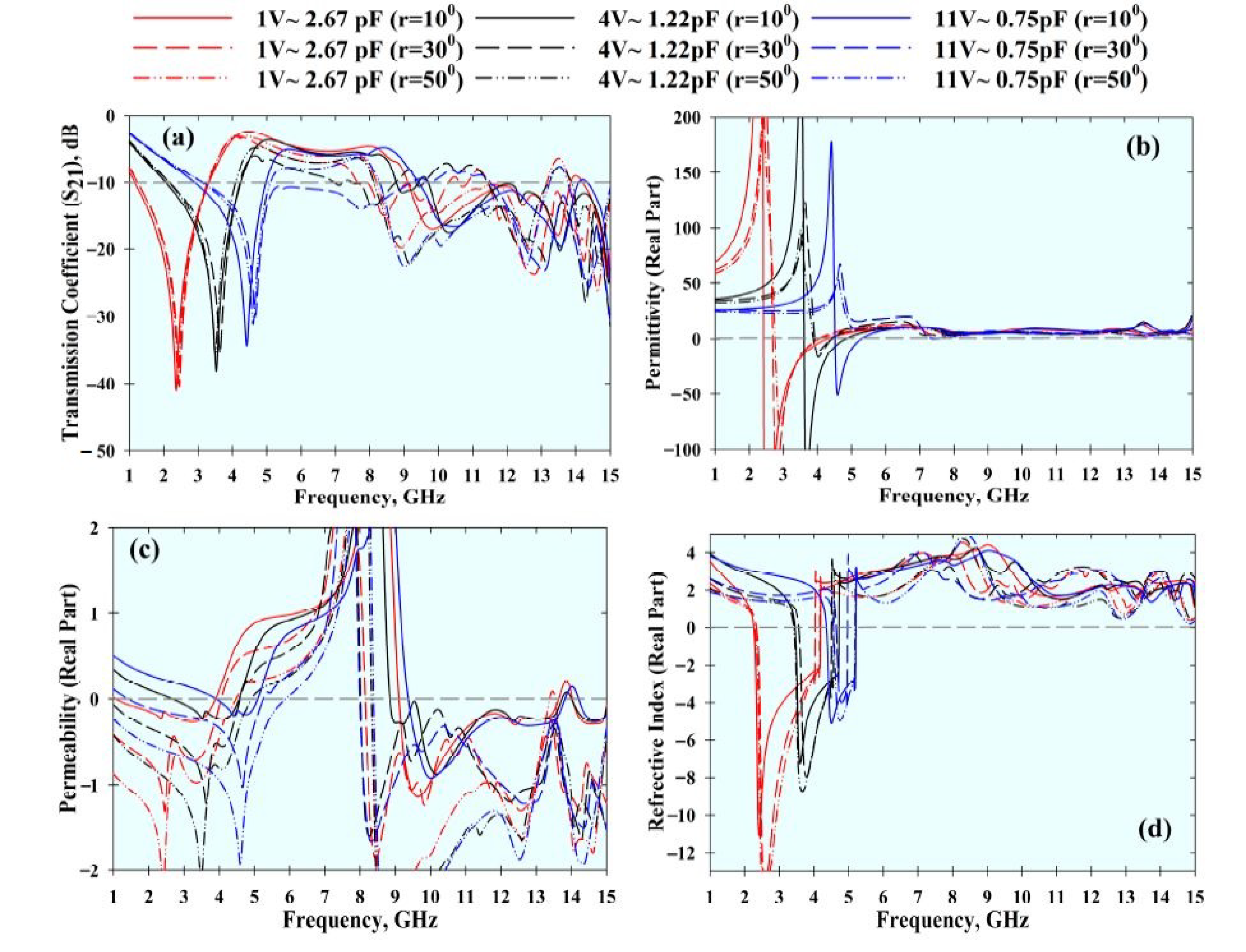
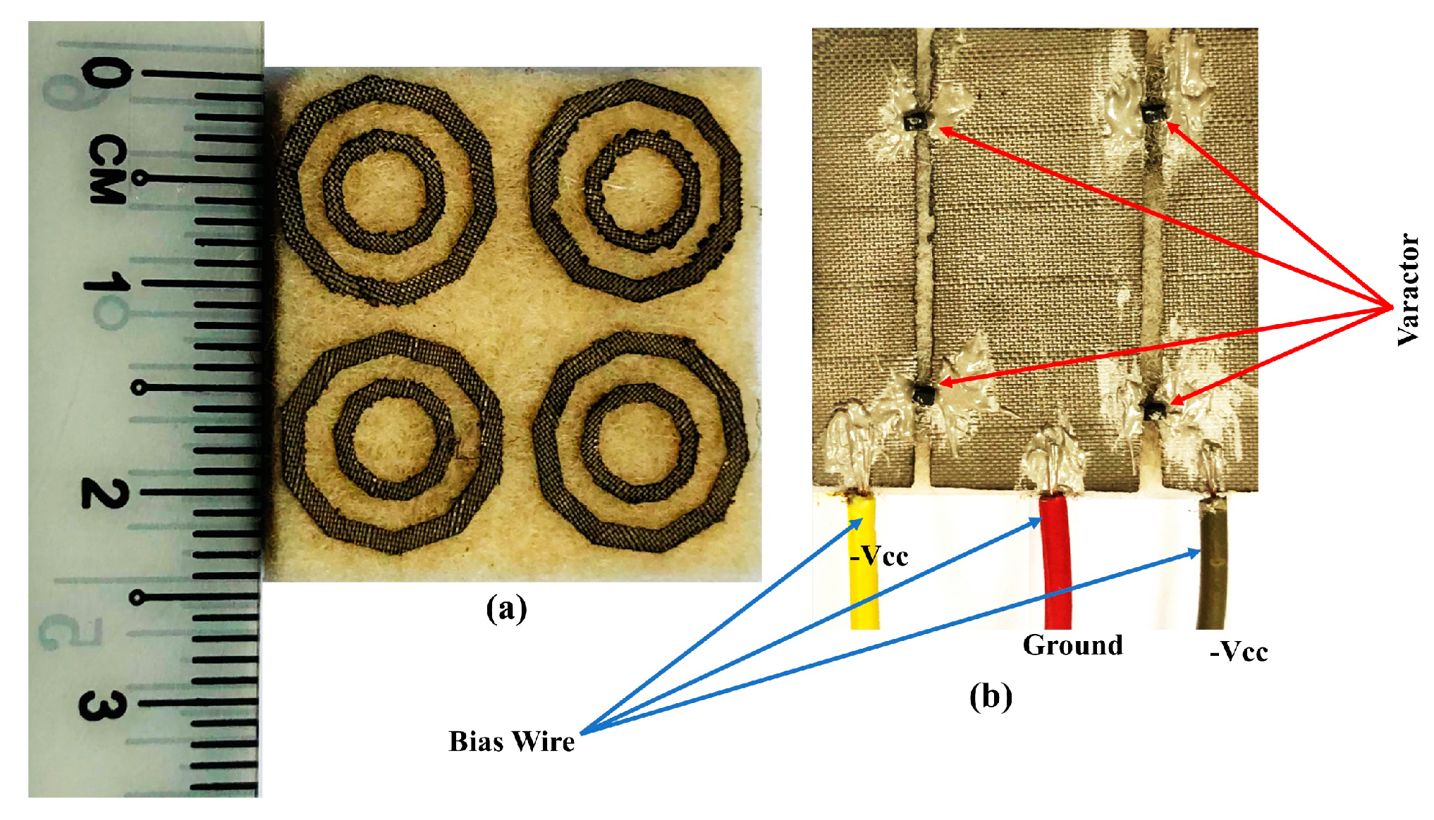
4.3. Experimental Validations
5. Conclusions
Author Contributions
Funding
Institutional Review Board Statement
Informed Consent Statement
Data Availability Statement
Conflicts of Interest
References
- Engheta, N.; Ziolkowski, R.W. Metamaterials: Physics and Engineering Explorations; John Wiley & Sons, Inc.: Hoboken, NJ, USA, 2006. [Google Scholar] [CrossRef]
- Smith, D.R.; Schultz, S.; Markoš, P.; Soukoulis, C.M. Determination of effective permittivity and permeability of metamaterials from reflection and transmission coefficients. Phys. Rev. B Conden. Matter Mater. Phys. 2002, 65, 1–5. [Google Scholar] [CrossRef]
- Smith, D.R.; Padilla, W.J.; Vier, D.C.; Nemat-Nasser, S.C.; Schultz, S. Composite Medium with Simultaneously Negative Permeability and Permittivity. Phys. Rev. Lett. 2000, 84, 4184–4187. [Google Scholar] [CrossRef] [PubMed]
- Fan, B.; Filonov, D.; Ginzburg, P.; Podolskiy, V.A. Low-frequency nonlocal and hyperbolic modes in corrugated wire metamaterials. Opt. Express 2018, 26, 17541. [Google Scholar] [CrossRef] [PubMed]
- Filonov, D.; Kozlov, V.; Shmidt, A.; Steinberg, B.Z.; Ginzburg, P. Resonant metasurface with tunable asymmetric reflection. Appl. Phys. Lett. 2018, 113. [Google Scholar] [CrossRef]
- Alitalo, P.; Tretyakov, S. Electromagnetic cloaking with metamaterials. Mater. Today 2009, 12, 22–29. [Google Scholar] [CrossRef]
- Naserpour, M.; Zapata-Rodríguez, C.J.; Vuković, S.M.; Pashaeiadl, H.; Belić, M.R. Tunable invisibility cloaking by using isolated graphene-coated nanowires and dimers. Sci. Rep. 2017, 7, 1–14. [Google Scholar] [CrossRef]
- Zahertar, S.; Wang, Y.; Tao, R.; Xie, J.; Fu, Y.Q.; Torun, H. A fully integrated biosensing platform combining acoustofluidics and electromagnetic metamaterials. J. Phys. D Appl. Phys. 2019, 52. [Google Scholar] [CrossRef]
- Panda, A.K.; Pattnaik, M.; Swain, R. CSRR Embedded CPW Band-Stop Filter. IETE J. Res. 2019, 1–7. [Google Scholar] [CrossRef]
- Salim, A.; Lim, S. Review of recent metamaterial microfluidic sensors. Sensors 2018, 18, 232. [Google Scholar] [CrossRef]
- Presse, A.; Tarot, A.C. Miniaturized bendable 400 MHz artificial magnetic conductor. Appl. Phys. A Mater. Sci. Process. 2016, 122, 1–5. [Google Scholar] [CrossRef]
- Fazilah, A.F.M.; Jusoh, M.; Sabapathy, T.; Abbasi, Q.H.; Hossain, K.; Rahim, H.A.; Yasin, M.N.M.; Osman, M.N.; Kamarudin, M.R.; Majid, H.A.; et al. A Flexible and Compact Metamaterial UHF RID Tag for Remote Sensing in Human Health. In Proceedings of the 2020 International Conference on UK-China Emerging Technologies, UCET 2020, Glasgow, UK, 20–21 August 2020; IEEE: New York, NY, USA, 2020; pp. 1–4. [Google Scholar]
- Bait-Suwailam, M.M.; Almoneef, T.S.; Alomainy, A. A Dual-Band Flexible Frequency-Reconfigurable Metamaterial Absorber using Modified Split-Ring Resonator. In Proceedings of the 2019 2nd IEEE Middle East North Africa Communications Conference MENACOMM 2019, Manama, Bahrain, 19–21 November 2019; pp. 1–4. [Google Scholar] [CrossRef]
- Gao, G.; Hu, B.; Wang, S.; Yang, C. Wearable planar inverted-F antenna with stable characteristic and low specific absorption rate. Microw. Opt. Technol. Lett. 2018, 60, 876–882. [Google Scholar] [CrossRef]
- Dobrykh, D.; Filonov, D.; Mikhailovskaya, A.; Ginzburg, P. Dynamically reconfigurable metamaterial-based scatterer. In Proceedings of the 14th European Conference on Antennas and Propagation, EuCAP 2020, Copenhagen, Denmark, 15–20 March 2020; IEEE: New York, NY, USA, 2020; pp. 1–4. [Google Scholar]
- Oliveri, G.; Werner, D.H.; Massa, A. Reconfigurable electromagnetics through metamaterials-a review. Proc. IEEE 2015, 103, 1034–1056. [Google Scholar] [CrossRef]
- Griguer, H.; Drissi, M.; Marzolf, E.; Lalj, H.; Riouch, F. Design and characterization of a tunable DNG metamaterial superstrate for small beam steering antennas. Appl. Phys. A Mater. Sci. Process. 2011, 103, 895–898. [Google Scholar] [CrossRef]
- Sievenpiper, D.F.; Schaffner, J.H.; Jae Song, H.; Loo, R.Y.; Tangonan, G. Two-Dimensional Beam Steering Using an Electrically Tunable Impedance Surface. IEEE Trans. Antennas Propag. 2003, 51, 2713–2722. [Google Scholar] [CrossRef]
- Bakır, M.; Karaaslan, M.; Dincer, F.; Delihacioglu, K.; Sabah, C. Tunable perfect metamaterial absorber and sensor applications. J. Mater. Sci. Mater. Electron. 2016, 27, 12091–12099. [Google Scholar] [CrossRef]
- Kim, H.K.; Lee, D.; Lim, S. Frequency-tunable metamaterial absorber using a varactor-loaded fishnet-like resonator. Appl. Opt. 2016, 55, 4113. [Google Scholar] [CrossRef]
- Tian, X.; Lee, P.M.; Tan, Y.J.; Wu, T.L.Y.; Yao, H.; Zhang, M.; Li, Z.; Ng, K.A.; Tee, B.C.K.; Ho, J.S. Wireless body sensor networks based on metamaterial textiles. Nat. Electron. 2019, 2, 243–251. [Google Scholar] [CrossRef]
- Martinez-Estrada, M.; Moradi, B.; Fernández-Garcia, R.; Gil, I. Impact of Manufacturing Variability and Washing on Embroidery Textile Sensors. Sensors 2018, 18, 3824. [Google Scholar] [CrossRef] [PubMed]
- Moradi, B.; Fernández-García, R.; Gil, I. E-textile embroidered metamaterial transmission line for signal propagation control. Materials 2018, 11, 955. [Google Scholar] [CrossRef]
- Zhang, K.; Jack Soh, P.; Yan, S. Meta-wearable antennas-a review of metamaterial based antennas in wireless body area networks. Materials 2021, 14, 149. [Google Scholar] [CrossRef]
- Tartare, G.; Zeng, X.; Koehl, L. Development of a wearable system for monitoring the firefighter’s physiological state. In Proceedings of the 2018 IEEE Industrial Cyber-Physical Systems (ICPS), St. Petersburg, Russia, 15–18 May 2018; pp. 561–566. [Google Scholar] [CrossRef]
- Wu, J.F.; Qiu, C.; Wang, Y.; Zhao, R.; Cai, Z.P.; Zhao, X.G.; He, S.S.; Wang, F.; Wang, Q.; Li, J.Q. Human limb motion detection with novel flexible capacitive angle sensor based on conductive textile. Electronics 2018, 7, 192. [Google Scholar] [CrossRef]
- Saenz-Cogollo, J.F.; Pau, M.; Fraboni, B.; Bonfiglio, A. Pressure mapping mat for tele-home care applications. Sensors 2016, 16, 365. [Google Scholar] [CrossRef] [PubMed]
- Singh, H.; Sohi, B.S.; Gupta, A. A compact CRLH metamaterial with wide band negative index characteristics. Bull. Mater. Sci. 2019, 42, 1–11. [Google Scholar] [CrossRef]
- Ourir, A.; Burokur, S.N.; de Lustrac, A. Electronically reconfigurable metamaterial for compact directive cavity antennas. Electron. Lett. 2007, 43, 698. [Google Scholar] [CrossRef]
- Shadrivov, I.V.; Kozyrev, A.B.; Van Der Weide, D.W.; Kivshar, Y.S. Tunable transmission and harmonic generation in nonlinear metamaterials. Appl. Phys. Lett. 2008, 93. [Google Scholar] [CrossRef]
- Skyworks SMV1232 SERIES Hyperabrupt Junction Tuning Varactors. Available online: https://www.skyworksinc.com/products/diodes/smv1232-series (accessed on 15 September 2020).
- Mishra, R.N.; Arora, A.; Singh, S.; Bhattacharyya, S. A split ring resonator (SRR) based metamaterial structure for bandstop filter applications. In Proceedings of the 2017 IEEE Applied Electromagnetics Conference (AEMC), Aurangabad, India, 19–22 December 2017; IEEE: New York, NY, USA, 2017; pp. 1–2. [Google Scholar]
- Chen, X.; Grzegorczyk, T.M.; Wu, B.I.; Pacheco, J.; Kong, J.A. Robust method to retrieve the constitutive effective parameters of metamaterials. Phys. Rev. E Stat. Physics Plasmas Fluids Relat. Interdiscip. Top. 2004, 70, 7. [Google Scholar] [CrossRef] [PubMed]
- Hossain, K.; Sabapathy, T.; Jusoh, M.; Soh, P.J.; Fazilah, A.F.M.; Halim, A.A.A.; Raghava, N.S.; Podilchak, S.K.; Schreurs, D.; Abbasi, Q.H. ENG and NZRI Characteristics of Decagonal-Shaped Metamaterial for Wearable Applications. In Proceedings of the 2020 International Conference on UK-China Emerging Technologies, UCET 2020, Glasgow, UK, 20–21 August 2020; IEEE: New York, NY, USA, 2020; pp. 1–4. [Google Scholar]
- Numan, A.B.; Sharawi, M.S. Extraction of material parameters for metamaterials using a full-wave simulator [education column]. IEEE Antennas Propag. Mag. 2013, 55, 202–211. [Google Scholar] [CrossRef]
- Islam, S.S.; Faruque, M.R.I.; Islam, M.T. A new direct retrieval method of refractive index for the metamaterial. Curr. Sci. 2015, 109, 337–342. [Google Scholar]
- Al-Bawri, S.S.; Hwang Goh, H.; Islam, M.S.; Wong, H.Y.; Jamlos, M.F.; Narbudowicz, A.; Jusoh, M.; Sabapathy, T.; Khan, R.; Islam, M.T. Compact Ultra-Wideband Monopole Antenna Loaded with Metamaterial. Sensors 2020, 20, 796. [Google Scholar] [CrossRef]
- CircuitWorks® Conductive Silver Epoxy|Chemtronics Bonding|Chemtronics. Available online: https://www.chemtronics.com/circuitworks-conductive-epoxy-2 (accessed on 12 February 2021).
- You, K.Y. Materials Characterization Using Microwave Waveguide System. In Microwave Systems and Applications; InTech: London, UK, 2017; pp. 341–358. [Google Scholar]


| Reference | Method/Component | Substrate Type & Thickness | Varactor Tuning Mechanism | Tunable Parameters | Tuning Ratio (%) |
|---|---|---|---|---|---|
| [29] | Varactor | FR3-epoxy (rigid) & 1.4 mm | External DC power | Reflection coefficient phase | 3.72 |
| [17] | Varactor | RT/Duroid (rigid) & 0.8 mm | – | Medium index/ refractive index | 3.34 |
| [19] | Varactor | FR-4 (rigid) & 1.6 mm | – | Absorption range | 9.24 |
| [15] | Varactor and photodiode | FR-4 (rigid) & 1.5 mm | Light intensity control using photodiodes. | MNG properties/ artificial magnon resonance | – |
| [30] | Varactor | Rogers R4003 (rigid) & 0.5 mm | Varying the amplitude of the propagating EM waves | Magnetic resonance and transmission coefficient | – |
| This work | Varactor | Felt (Flexible) & 3 mm | External DC power | Transmission coefficient (S21), ENG, MNG, NRI and DNG properties | S21 = 104.97, ENG = 72.21, MNG = 80.81, NRI = 66.83, and DNG = 66.83 |
| Parameters | W | L | R1 | R2 | R3 | R4 | G1 | h | t |
|---|---|---|---|---|---|---|---|---|---|
| Value (mm) | 12 | 12 | 5.6 | 4.4 | 3.1 | 2.1 | 1 | 3 | 0.17 |
| Array Structure | ENG BW (GHz) | MNG BW (GHz) | NRI BW (GHz) | DNG BW (GHz) |
|---|---|---|---|---|
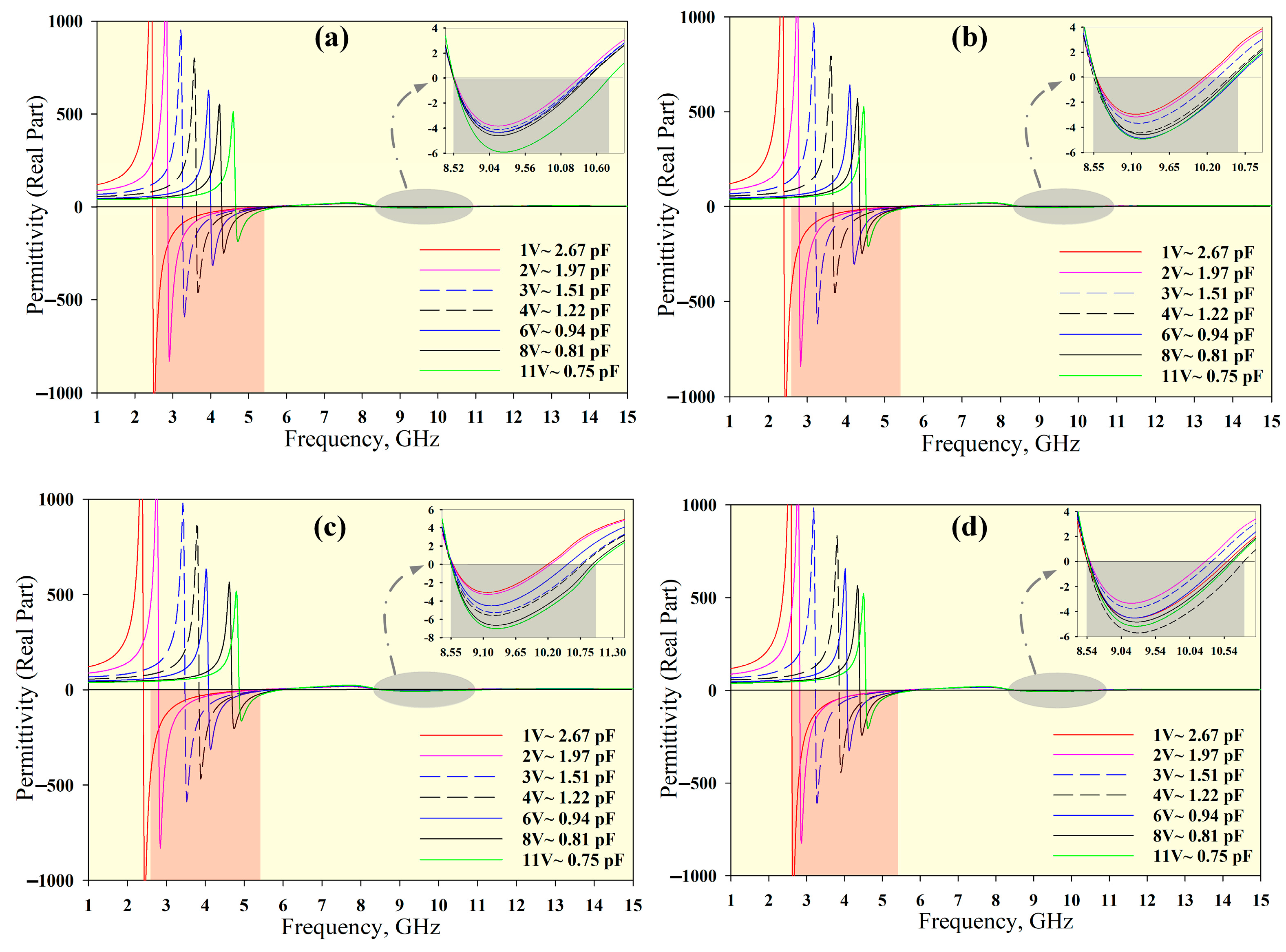
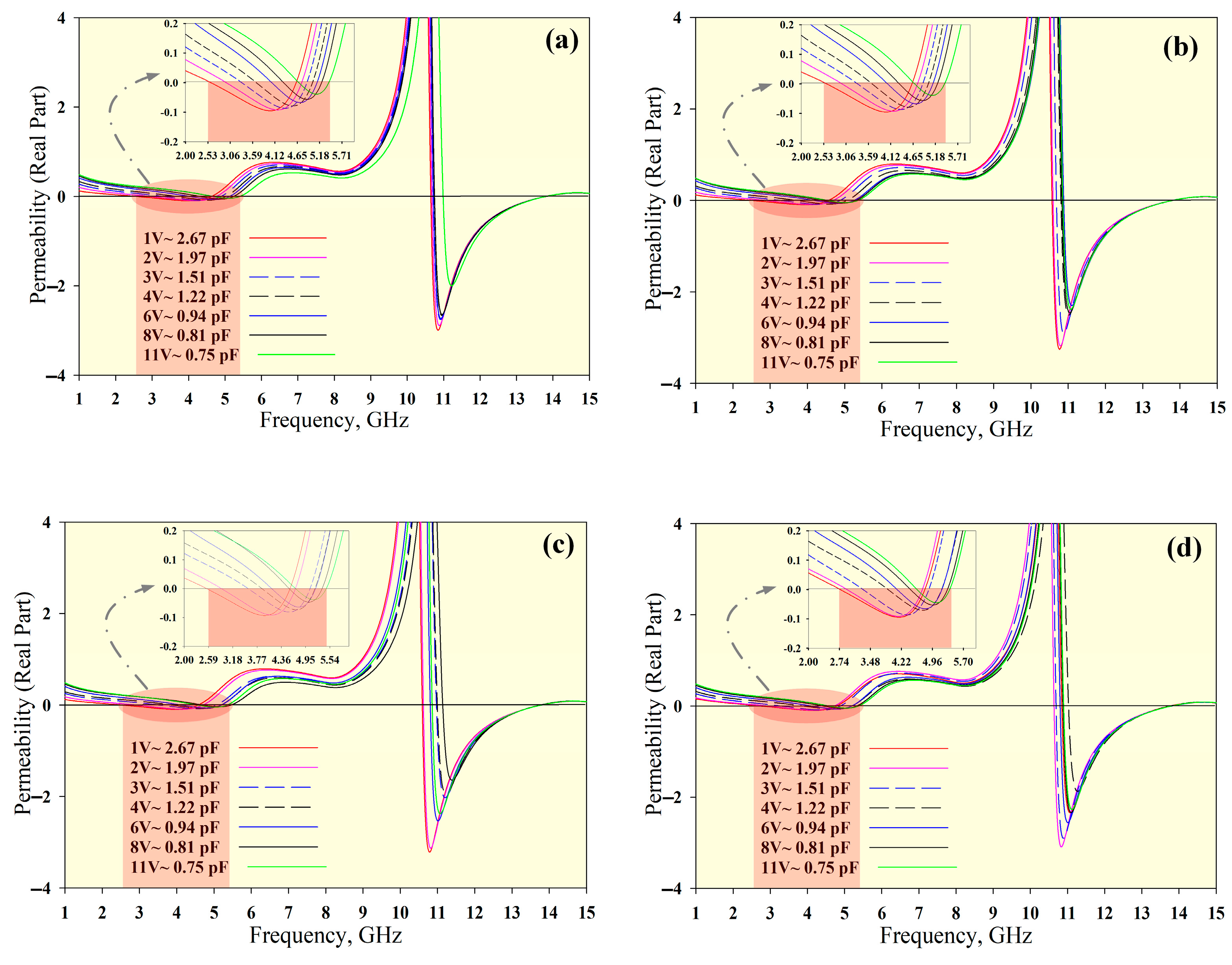
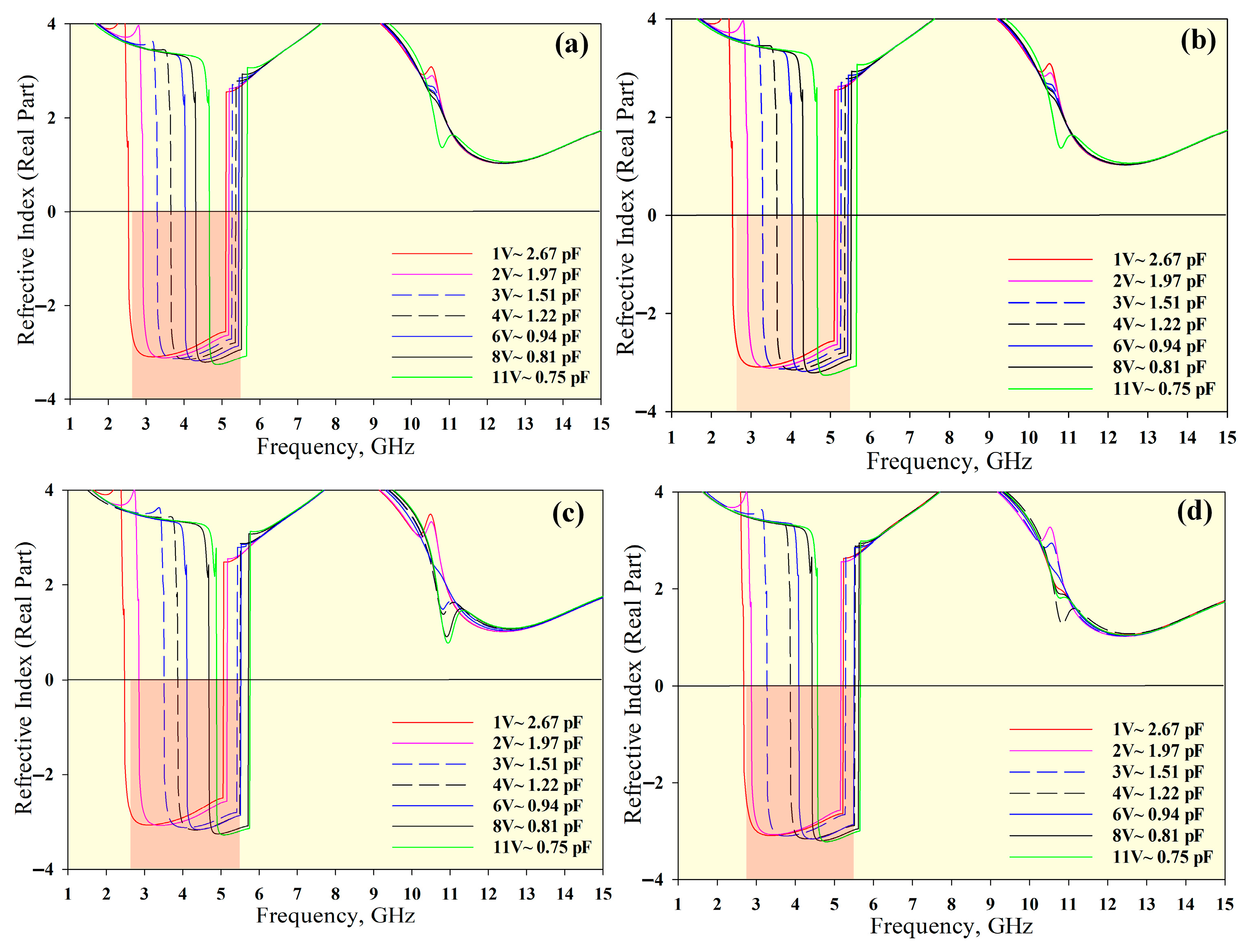
| 1 × 1 | 2.46–5.86 & 8.52–10.8 | 2.54–5.40 & 10.64–13.77 | 2.53–5.66 | 2.54–5.40 |
| 1 × 2 | 2.40–5.84 & 8.55–10.64 | 2.53–5.40 & 10.57–13.78 | 2.46–5.65 | 2.53–5.40 |
| 2 × 1 | 2.40–5.96 & 8.55–11.00 | 2.59–5.41 & 10.59–13.78 | 2.47–5.76 | 2.59–5.41 |
| 2 × 2 | 2.60–5.84 & 8.54–10.83 | 2.74–5.39 & 10.63–13.79 | 2.67–5.65 | 2.74–5.39 |
| Array Structure | S21 BW (GHz) | ENG BW (GHz) | MNG BW (GHz) | NRI BW (GHz) | DNG BW (GHz) |
|---|---|---|---|---|---|
| Simulated | 1.7–5.80 | 2.60–5.84 | 2.74–5.39 | 2.67–5.65 | 2.74–5.39 |
| Measured | 1.77–5.68 | 2.69–5.73 | 2.36–5.56 | 2.75–5.51 | 2.75–5.51 |
Publisher’s Note: MDPI stays neutral with regard to jurisdictional claims in published maps and institutional affiliations. |
© 2021 by the authors. Licensee MDPI, Basel, Switzerland. This article is an open access article distributed under the terms and conditions of the Creative Commons Attribution (CC BY) license (http://creativecommons.org/licenses/by/4.0/).
Share and Cite
Hossain, K.; Sabapathy, T.; Jusoh, M.; Soh, P.J.; Jamaluddin, M.H.; Al-Bawri, S.S.; Osman, M.N.; Ahmad, R.B.; Rahim, H.A.; Mohd Yasin, M.N.; et al. Electrically Tunable Left-Handed Textile Metamaterial for Microwave Applications. Materials 2021, 14, 1274. https://doi.org/10.3390/ma14051274
Hossain K, Sabapathy T, Jusoh M, Soh PJ, Jamaluddin MH, Al-Bawri SS, Osman MN, Ahmad RB, Rahim HA, Mohd Yasin MN, et al. Electrically Tunable Left-Handed Textile Metamaterial for Microwave Applications. Materials. 2021; 14(5):1274. https://doi.org/10.3390/ma14051274
Chicago/Turabian StyleHossain, Kabir, Thennarasan Sabapathy, Muzammil Jusoh, Ping Jack Soh, Mohd Haizal Jamaluddin, Samir Salem Al-Bawri, Mohamed Nasrun Osman, R. Badlishah Ahmad, Hasliza A. Rahim, Mohd Najib Mohd Yasin, and et al. 2021. "Electrically Tunable Left-Handed Textile Metamaterial for Microwave Applications" Materials 14, no. 5: 1274. https://doi.org/10.3390/ma14051274
APA StyleHossain, K., Sabapathy, T., Jusoh, M., Soh, P. J., Jamaluddin, M. H., Al-Bawri, S. S., Osman, M. N., Ahmad, R. B., Rahim, H. A., Mohd Yasin, M. N., & Saluja, N. (2021). Electrically Tunable Left-Handed Textile Metamaterial for Microwave Applications. Materials, 14(5), 1274. https://doi.org/10.3390/ma14051274