Textile Antenna for Bio-Radar Embedded in a Car Seat

 ,
,  , , and
Abstract
1. Introduction
2. Material and Methods
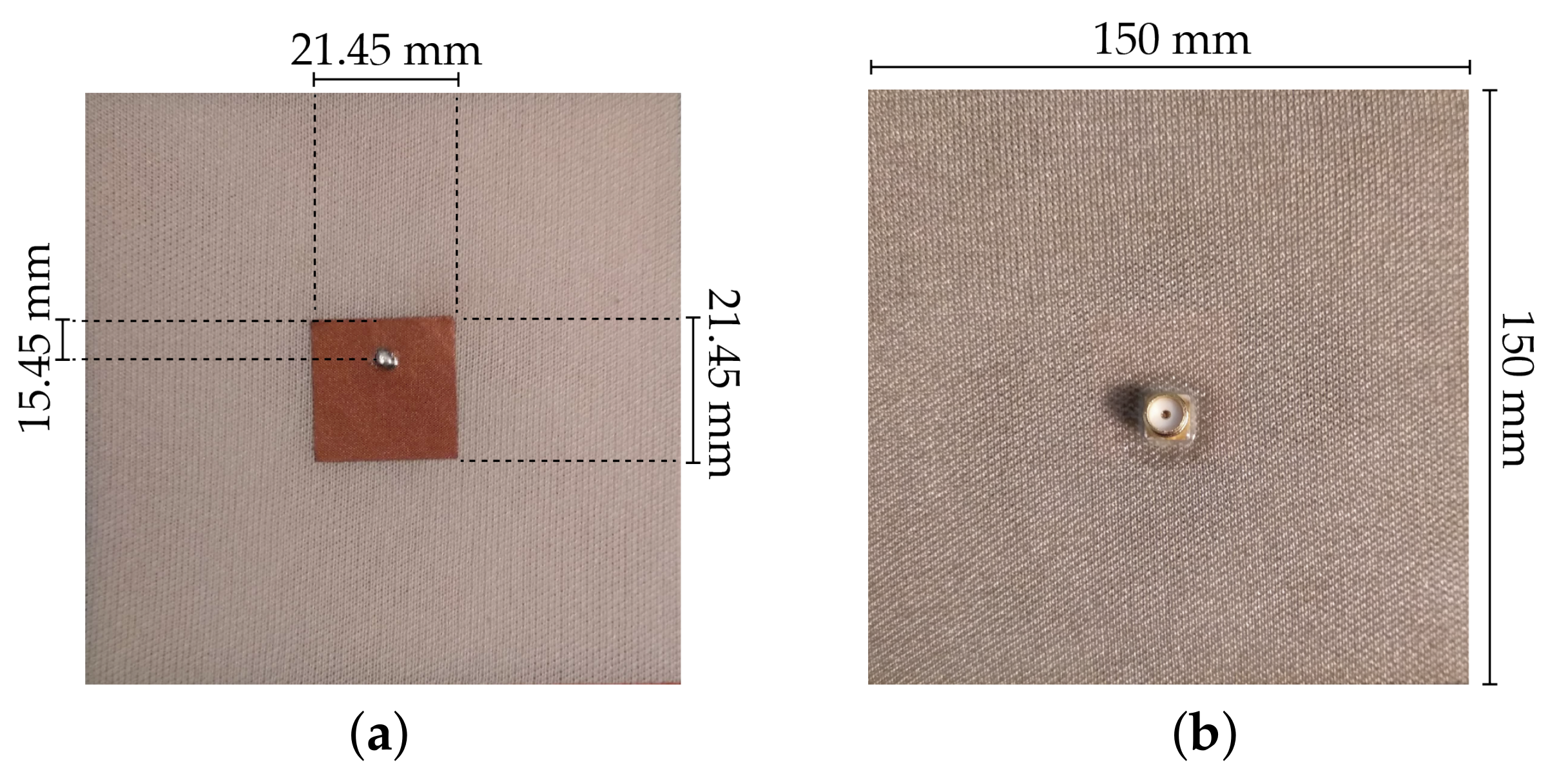
2.1. Development of a Continuous Substrate Integrating the Ground Plane
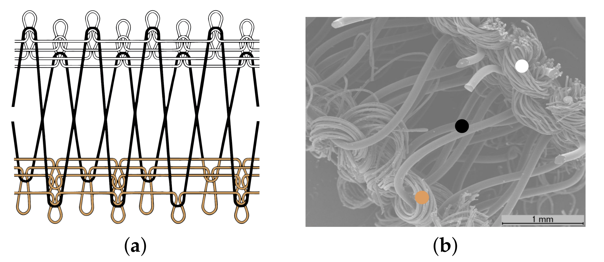
- Dielectric substrate (front side layer-white): a 100% Polyester yarn;
- Spacer yarn (interior layer-black): a Monofilament FH yarn, 100% Polyester (PolyEthylene Terephthalate, PET), 225 dtex, produced by Monosuisse AG (Emmenbrücke, Switzerland);
- Conductive layer (back side layer-brown): a Shieldex® 117/17 dtex Z-turns HC+B yarn, produced by Shieldex Trading (Palmyra, PA, USA).
2.1.1. Characterization of the Structural Parameters
2.1.2. Characterization of the Electromagnetic Properties
Conductivity
Permittivity and Loss Tangent
3. Development of Textile Antenna for Bio-Radar
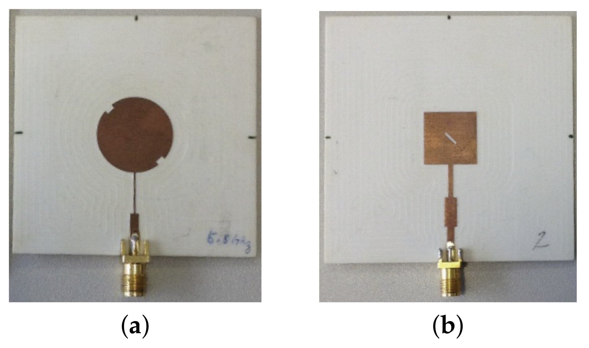
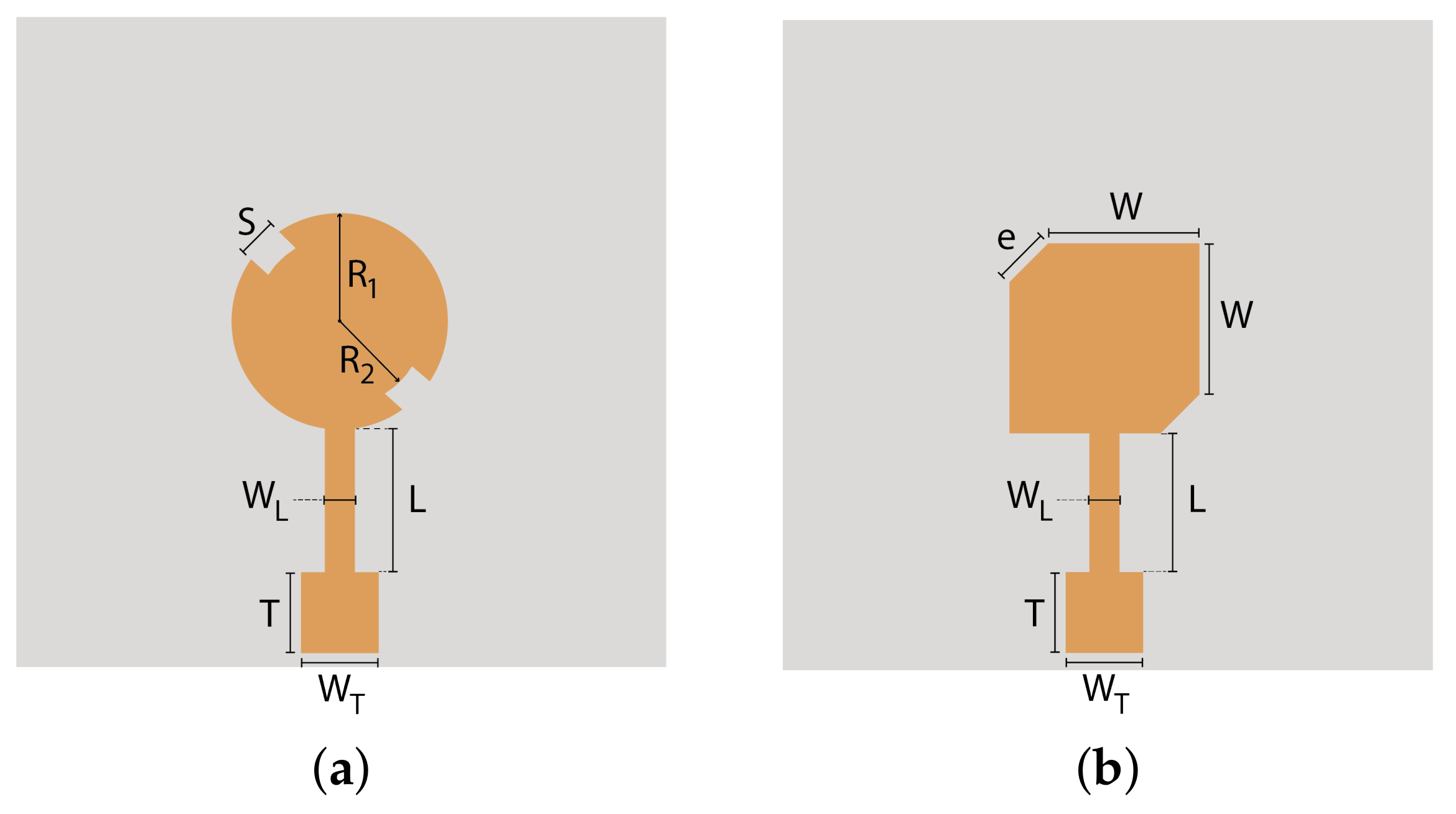
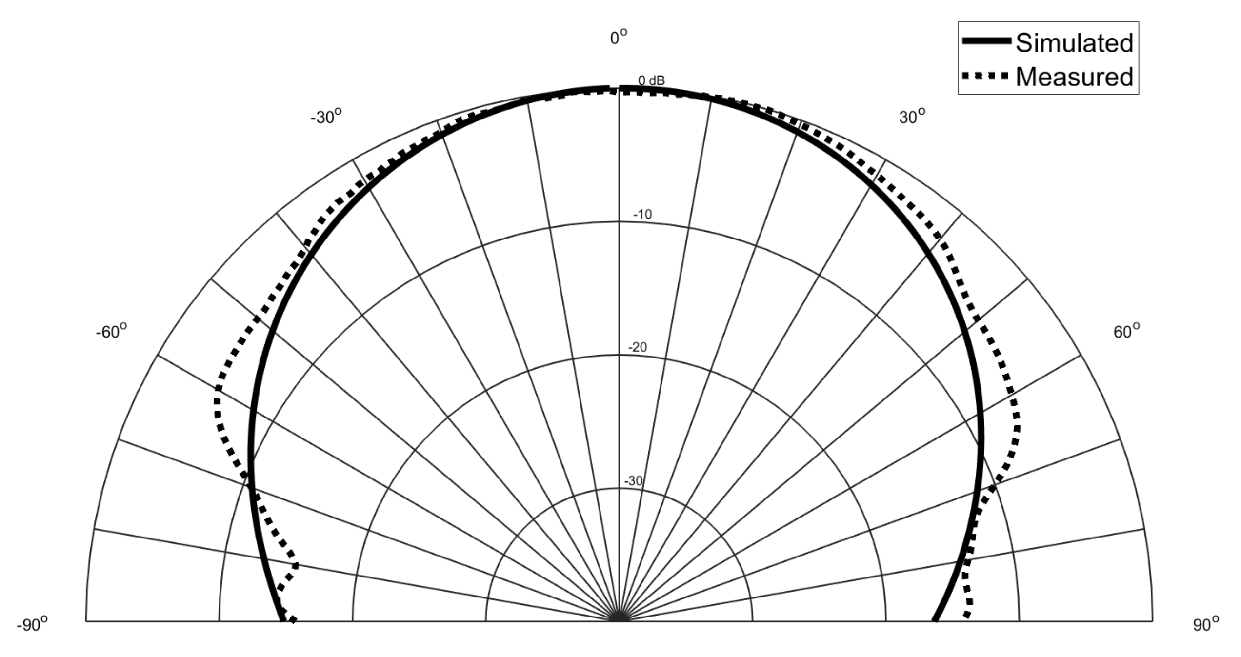
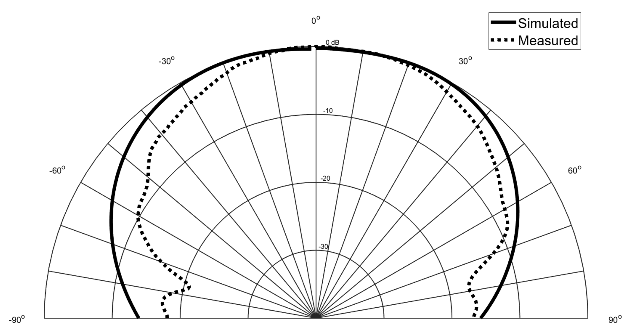
3.1. Design of Textile Antennas
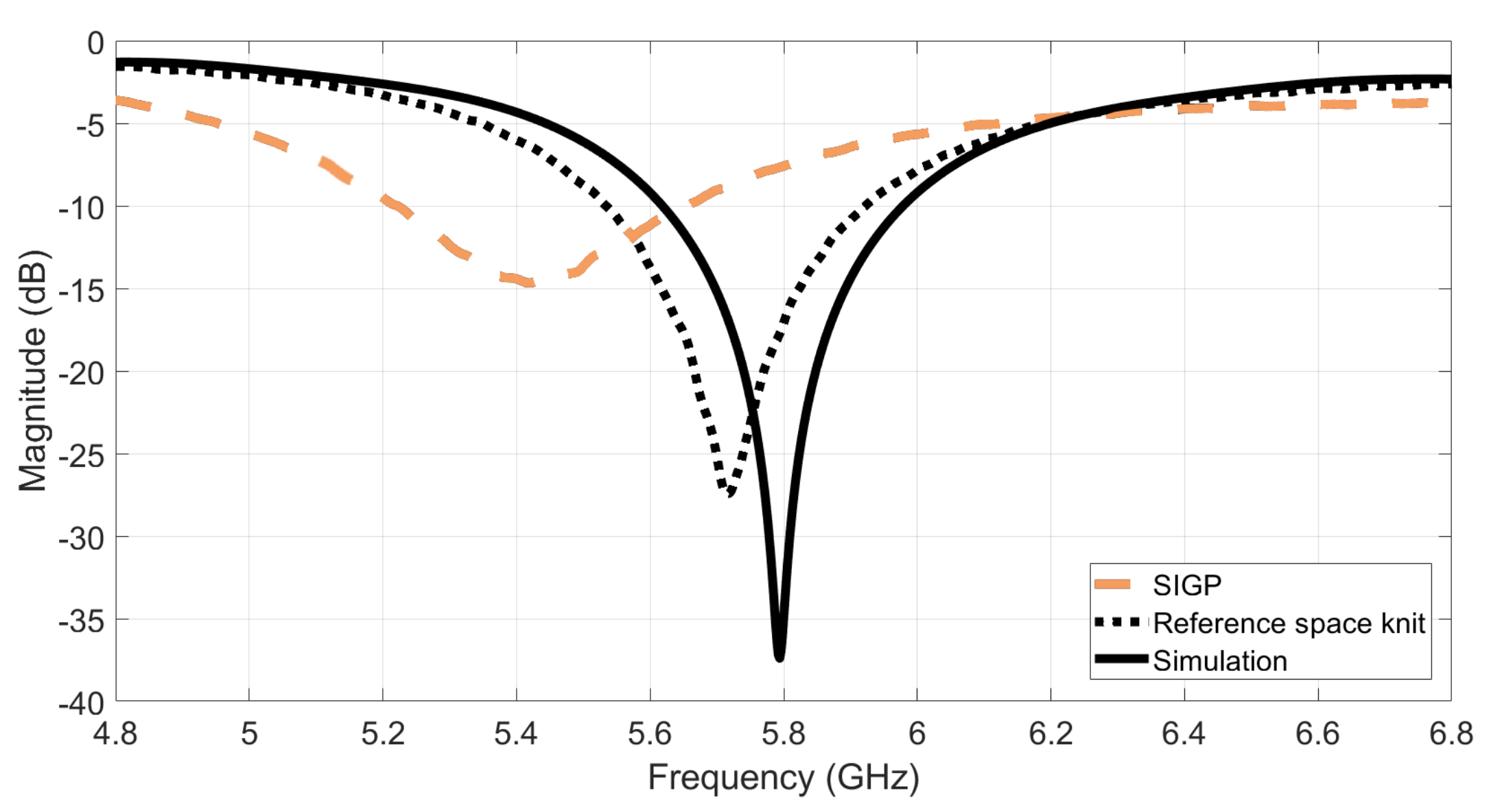
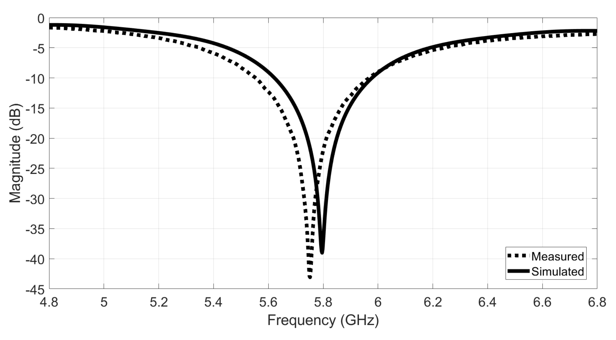
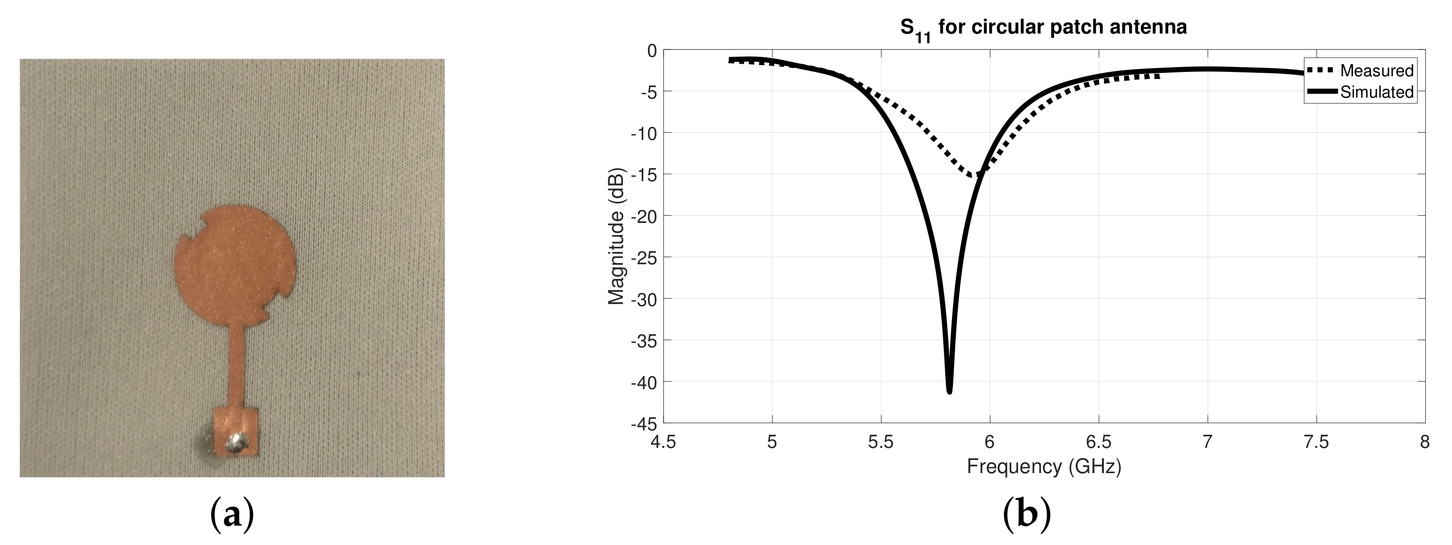
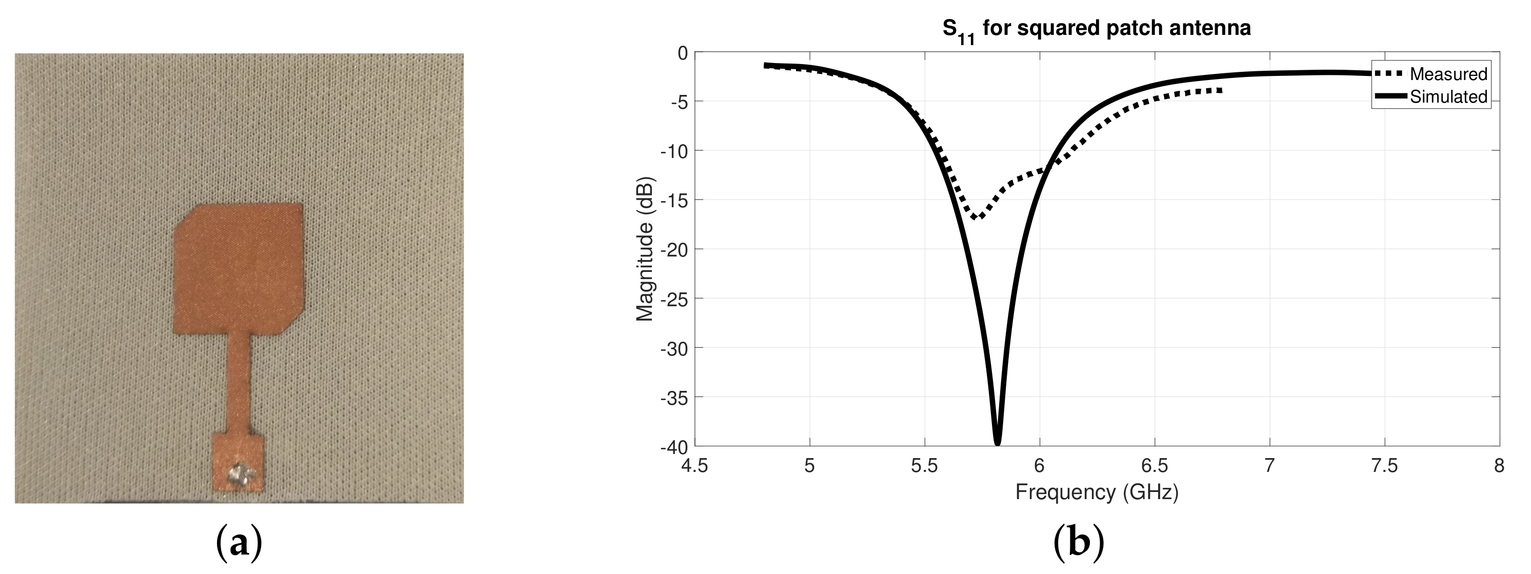
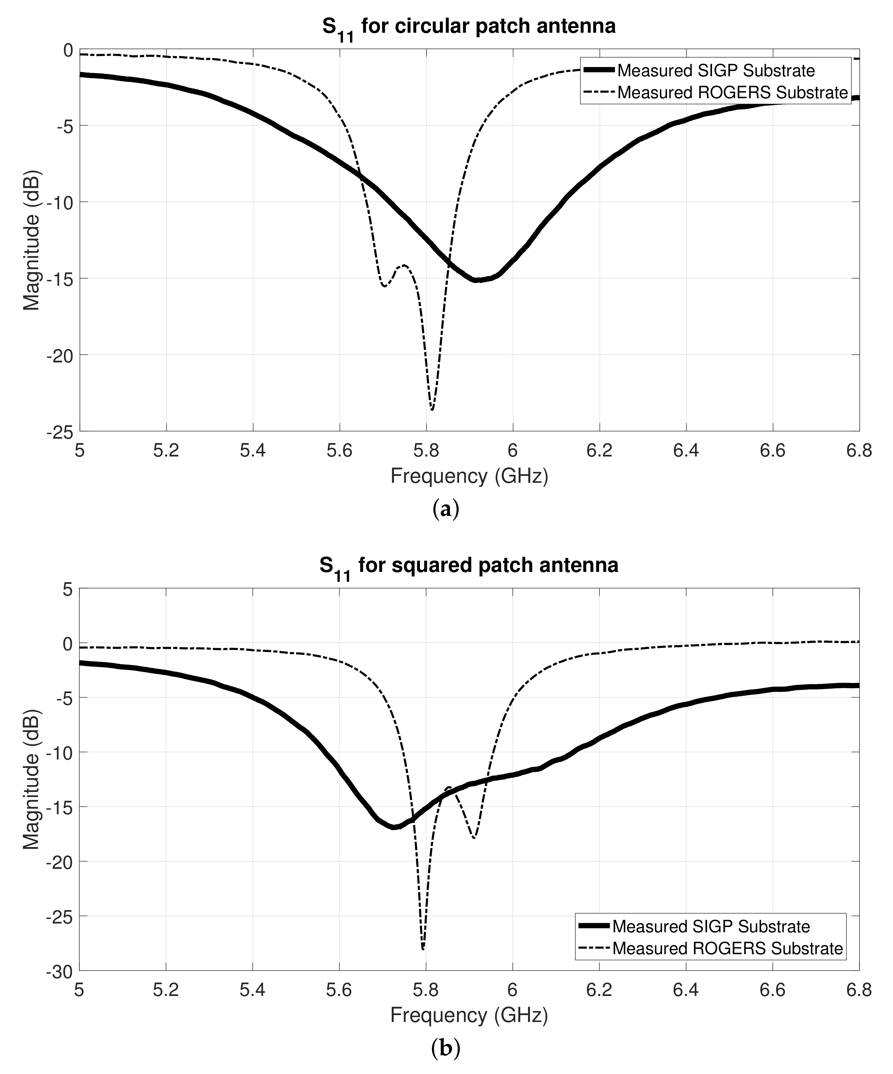
3.2. Measured Parameters of Textile Antennas
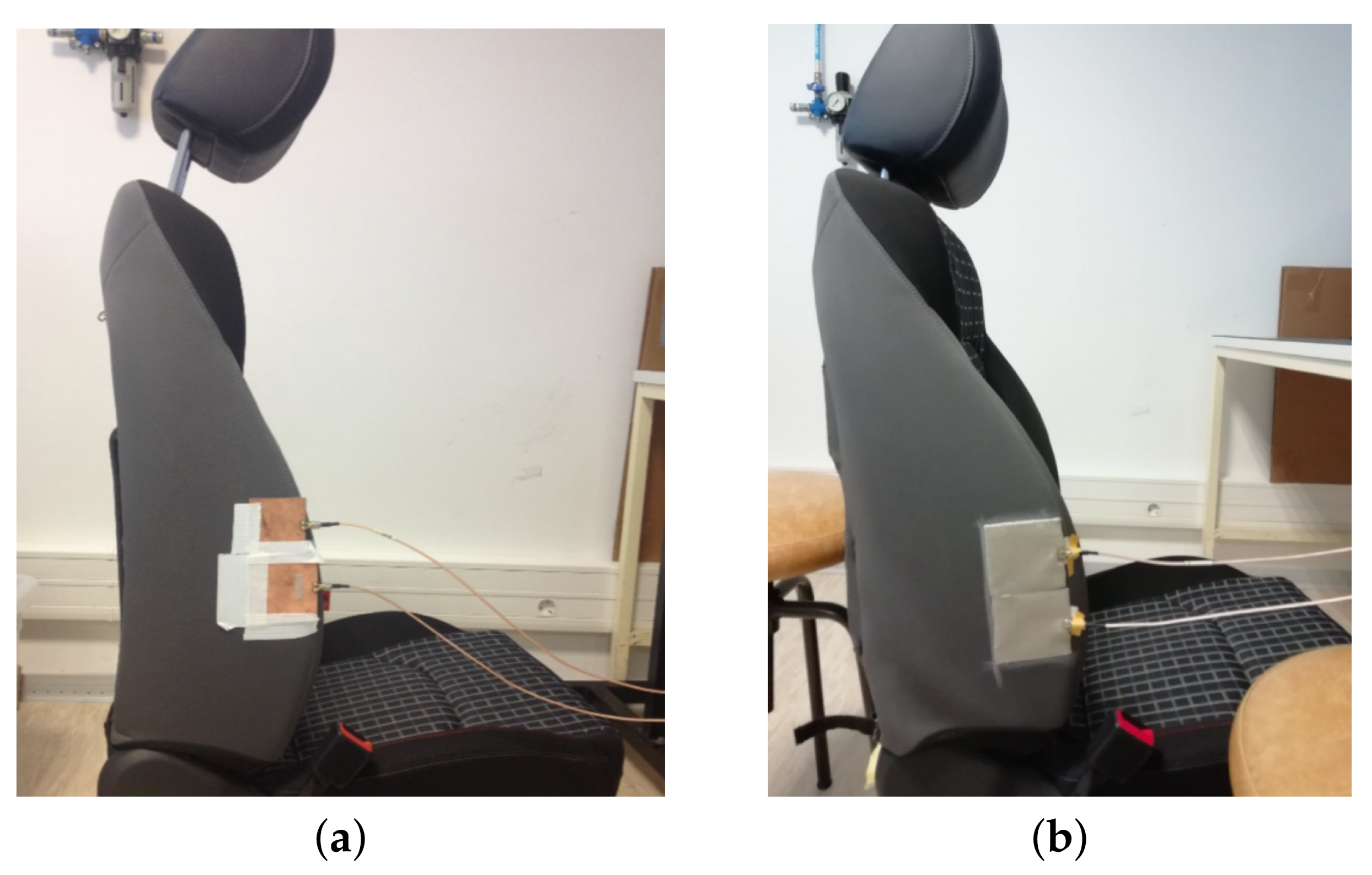
4. Practical Implementation
4.1. Textile Antenna Validation Test
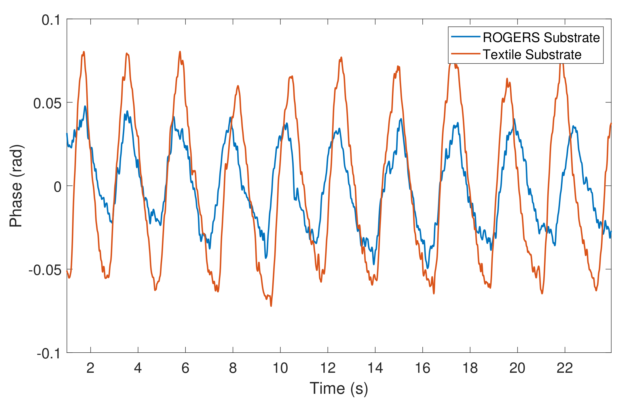
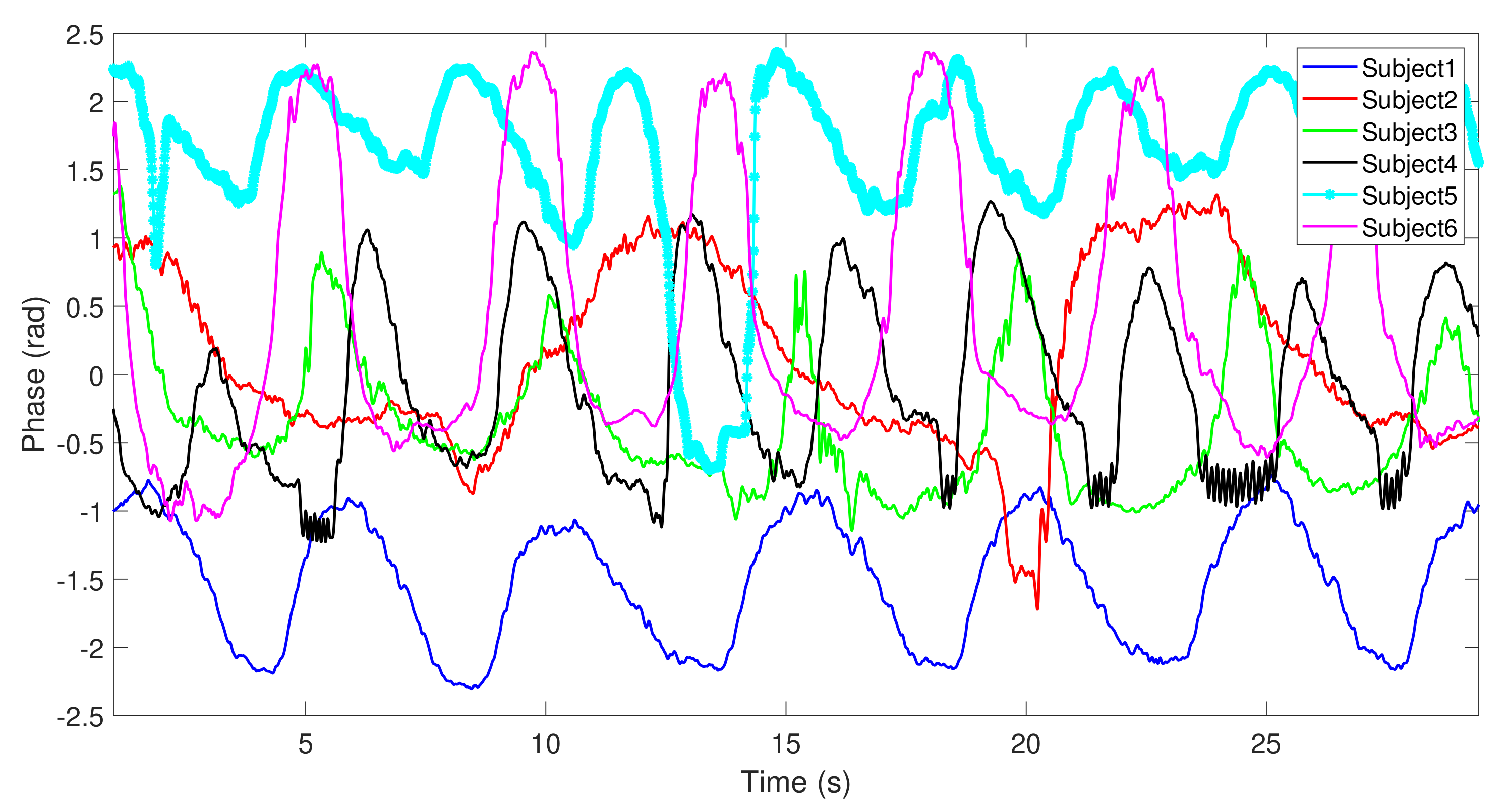
4.2. Bio-Radar Validation
5. Discussion
6. Conclusions
Author Contributions
Funding
Institutional Review Board Statement
Informed Consent Statement
Data Availability Statement
Conflicts of Interest
Abbreviations
| CW | Continuous Wave |
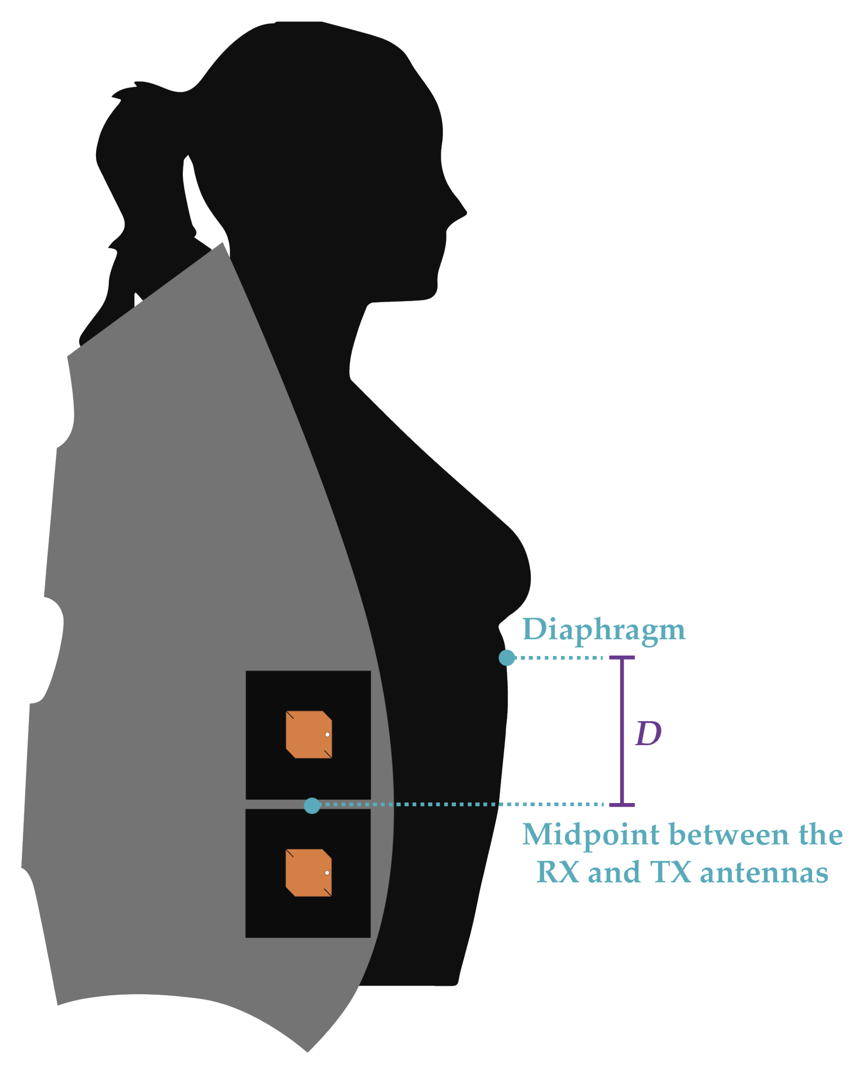
| D | Distance |
| LHCP | Left Hand Circular Polarization |
| PCPTF | Pure Copper Polyester Taffeta Fabric |
| PET | Polyester Ethylene Terephthalate |
| RH | Relative Humidity |
| RX | Reception |
| SDR | Software Defined Radio |
| SEM | Scanning Electronic Microscope |
| SIGP | Substrate Integrating the Ground Plane |
| SIW | Substrate Integrated Waveguide |
| SNR | Signal-to-Noise Ratio |
| SMA | SubMiniature version A |
| TX | Transmission |
| UWB | Ultra-Wide Band |
| VNA | Vector Network Analyser |
References
- Boric-Lubecke, O.; Lubecke, V.M.; Droitcour, A.D.; Park, B.-K.; Singh, A. Doppler Radar Physiological Sensing; John Wiley & Sons: Cambridge, UK, 2015. [Google Scholar]
- Gouveia, C.; Loss, C.; Pinho, P.; Vieira, J. Different Antenna Designs for Non-Contact Vital Signs Measurement: A Review. Electronics 2019, 8, 1294. [Google Scholar] [CrossRef]
- Diewald, A.R. RF-based Child Occupation Detection in the Vehicle Interior. In Proceedings of the 17th International Radar Symposium (IRS), Krakow, Poland, 10–12 May 2016; pp. 1–4. [Google Scholar]
- Hui, X.; Kan, E.C. Seat Integration of RF Vital-Sign Monitoring. In Proceedings of the IEEE MTT-S International Microwave Biomedical Conference (IMBioC), Nanjing, China, 6–8 May 2019; pp. 1–3. [Google Scholar]
- Schires, E.; Lande, T.S. Vital Sign Monitoring Through the Back Using an UWB Impulse Radar With Body Coupled Antennas. IEEE Trans. Biomed. Circuits Syst. 2018, 12, 292–302. [Google Scholar] [CrossRef] [PubMed]
- Cheng, S.; Hallbjorner, P.; Rydberg, A. Array Antenna for Body-Worn Automotive Harmonic Radar Tag. In Proceedings of the 3rd European Conference on Antennas and Propagation, Berlin, Germany, 23–27 March 2009; pp. 2823–2827. [Google Scholar]
- Agneessens, S. A Through Wall Doppler Radar System: Active Textile Antenna Design, Prototyping and Experiment. In Proceedings of the IEEE Topical Conference on Wireless Sensors and Sensor Networks (WiSNet), Austin, TX, USA, 20–23 January 2013; pp. 16–18. [Google Scholar]
- Salvado, R.; Loss, C.; Gonçalves, R.; Pinho, P. Textile Materials for the Design of Wearable Antennas: A Survey. Sensors 2012, 12, 15841–15857. [Google Scholar] [CrossRef] [PubMed]
- Zhang, L.; Wang, Z.; Volakis, J.L. Textile Antennas and Sensors for Body-Worn Applications. IEEE Antennas Wirel. Propag. Lett. 2012, 11, 1690–1693. [Google Scholar] [CrossRef]
- Loss, C.; Salvado, R.; Gonçalves, R.; Pinho, P. Influence of the Laminating Manufacturing Technique on the S11 Parameter of Printed Textile Antennas. In Proceedings of the IEEE MTT-S International Microwave Workshop Series on Advanced Materials and Processes for RF and THz Applications (IMWS-AMP), Pavia, Italy, 20–22 September 2017; p. 13. [Google Scholar]
- Scarpello, M.L.; Kazani, I.; Hertleer, C.; Rogier, H.; Ginste, D.V. Stability and efficiency of screen-printed wearable and washable antennas. IEEE Antennas Wirel. Propag. Lett. 2012, 11, 838–841. [Google Scholar] [CrossRef]
- Špůrek, J.; Vélim, J.; Cupal, M.; Raida, Z.; Prášek, J.; Hubálek, J. Slot loop antennas printed on 3D textile substrate. In Proceedings of the 21st International Conference on Microwave, Radar and Wireless Communications (MIKON), Krakow, Poland, 9–11 May 2016; pp. 1–3. [Google Scholar]
- Tsolis, A.; Whittow, W.G.; Alexandridis, A.A.; Yiannis, J.C.V. Embroidery and Related Manufacturing Techniques for Wearable Antennas: Challenges and Opportunities. Electronics 2014, 3, 314–338. [Google Scholar] [CrossRef]
- Ginestet, G. Embroidered Antenna-Microchip Interconnections and Contour Antennas in Passive UHF RFID Textile Tags. IEEE Antennas Wirel. Propag. Lett. 2017, 16, 1205–1208. [Google Scholar] [CrossRef]
- Alonso, L. Millimetre Wave Textile Integrated Waveguide Beamforming Antenna for Radar Applications. In Proceedings of the Global Symposium on Millimeter-Waves (GSMM), Montreal, QC, Canada, 25–27 May 2015; pp. 1–3. [Google Scholar]
- Yao, L.; Qiu, Y. Design and Fabrication of Microstrip Antennas Integrated in Three Dimensional Orthogonal Woven Composites. Compos. Sci. Technol. 2009, 69, 1004–1008. [Google Scholar] [CrossRef]
- Yao, L.; Jiang, M.; Zhou, D.; Xu, F.; Zhao, D.; Zhang, W.; Zhou, N.; Jiang, Q.; Qiu, Y. Fabrication and Characterization of Microstrip Array Antennas Integrated in the Three Dimensional Orthogonal Woven Composite. Compos. Part B 2011, 42, 885–890. [Google Scholar] [CrossRef]
- Weft Knitted Spacer Fabrics. U.S. Patent 6.779.369B2, 27 May 2004.
- Hertleer, C.; Laere, A.V.; Rogier, H.; Langenhove, L.V. Influence of Relative Humidity on Textile Antenna Performance. Text. Res. J. 2009, 80, 177–183. [Google Scholar] [CrossRef]
- Lilja, J.; Salonen, P.; Kaija, T.; Maagt, P.D. Design and Manufacturing of Robust Textile Antennas for Harsh Environments. IEEE Trans. Antennas Propag. 2012, 60, 4130–4140. [Google Scholar] [CrossRef]
- Kawabata, S. Measurement of the Mechanical Properties of Fabrics. In The Standarization and Analysys of Hand Evaluation, 2nd ed.; The Textile Machinery Society of Japan: Osaka, Japan, 1980; pp. 28–57. [Google Scholar]
- Hotaling, N.A.; Bharti, K.; Kriel, H.; Simon, C.G.J. DiameterJ: A Validated Open Source Nanofiber Diameter Measurement Tool. Biomaterials 2015, 61, 327–338. [Google Scholar] [CrossRef] [PubMed]
- Schineider, A.C.; Rasband, W.S.; Eliceiri, K.W. NIH Image to ImageJ: 25 years of Image Analysis. Nat. Methods 2012, 9, 671–675. [Google Scholar] [CrossRef] [PubMed]
- Test Method for Determing the Electrical Resistivity of a Printed Conductive Material; ASTM F-1896-98; ASTM International: West Conshohocken, PA, USA, 2004.
- Sankaralingam, S.; Bhaskar, G. Determination of Dielectric Constant of Fabric Materials and Their Use as Substrates for Design and Development of Antennas for Wearable Applications. IEEE Trans. Instrum. Meas. 2010, 59, 3122–3130. [Google Scholar] [CrossRef]
- Loss, C.; Gonçalves, R.; Pinho, P.; Salvado, R. Influence of Some Structural Parameters on the Dielectric Behavior of Materials for Textile Antennas. Text. Res. J. 2019, 89, 1131–1143. [Google Scholar] [CrossRef]
- Balanis, C.A. Antenna Theory Analysis and Design, 3rd ed.; Wiley Interscience: Hoboken, NJ, USA, 2005; pp. 811–876. [Google Scholar]
- Brebels, S.; Ryckaert, J.; Boris, C.; Donnay, S.; Raedt, W.D.; Beyne, E.; Mertens, R.P. SOP Integration and Codesign of Antennas. IEEE Trans. Adv. Packag. 2004, 27, 341–351. [Google Scholar] [CrossRef]
- Varum, T.; Matos, J.N.; Pinho, P. Non-Uniform Microstrip Antenna Array for DSRC in Single-Lane Structures. Sensors 2016, 16, 2101. [Google Scholar] [CrossRef] [PubMed]
- Gouveia, C.; Tomé, A.; Barros, F.; Soares, S.C.; Vieira, J.; Pinho, P. Study on the usage feasibility of continuous-wave radar for emotion recognition. Biomed. Signal Process. Control. 2020, 58, 101835. [Google Scholar] [CrossRef]


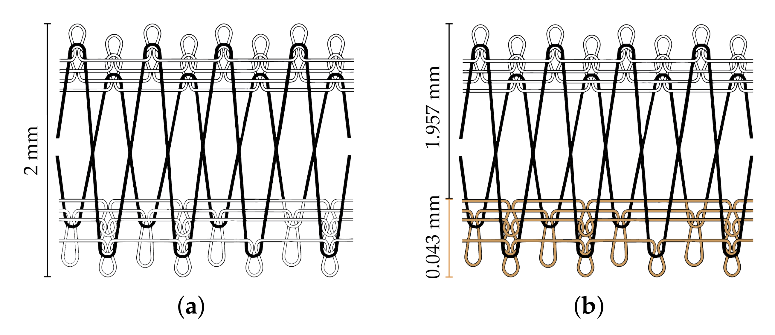
| Total Thickness (mm) | Thickness of Conductive Layer (mm) | Density (Number of Loops/cm) | Superficial Porosity (%) | |||||
|---|---|---|---|---|---|---|---|---|
| Front Side | Back Side | |||||||
| Wales | Courses | Wales | Courses | Front Side | Back Side | |||
| SIGP | 2 | 0.043 | 18 | 13 | 18 | 13 | 45.04 | 45.71 |
| Reference | 2 | - | 18 | 13 | 18 | 13 | 45.02 | 45.01 |
| Dimensions of the Samples (mm) | Sheet Resistance (/sq.) | Conductivity (kS/m) | |
|---|---|---|---|
| Length | Width | ||
| 30 | 60 | 0.428 | 54 |
| Circular Patch Antenna | Squared Patch Antenna | |||||||||||
|---|---|---|---|---|---|---|---|---|---|---|---|---|
| R1 | R2 | s | L | T | e | W | L | T | ||||
| 11.60 | 9.35 | 4.10 | 14.00 | 8.85 | 3.00 | 8.30 | 5.50 | 20.40 | 14.50 | 8.50 | 3.65 | 8.00 |
| Subject N | Gender | Chest-Wall Width [cm] | Height [m] | Distance D [cm] |
|---|---|---|---|---|
| 1 | Female | 70 | 1.50 | 7 |
| 2 | Male | 94.1 | 1.69 | 16 |
| 3 | Male | 84.5 | 1.73 | 16.5 |
| 4 | Female | 74.5 | 1.65 | 11.5 |
| 5 | Female | 75.5 | 1.56 | 12 |
| 6 | Male | 82 | 1.60 | 13 |
Publisher’s Note: MDPI stays neutral with regard to jurisdictional claims in published maps and institutional affiliations. |
© 2021 by the authors. Licensee MDPI, Basel, Switzerland. This article is an open access article distributed under the terms and conditions of the Creative Commons Attribution (CC BY) license (http://creativecommons.org/licenses/by/4.0/).
Share and Cite
Loss, C.; Gouveia, C.; Salvado, R.; Pinho, P.; Vieira, J. Textile Antenna for Bio-Radar Embedded in a Car Seat. Materials 2021, 14, 213. https://doi.org/10.3390/ma14010213
Loss C, Gouveia C, Salvado R, Pinho P, Vieira J. Textile Antenna for Bio-Radar Embedded in a Car Seat. Materials. 2021; 14(1):213. https://doi.org/10.3390/ma14010213
Chicago/Turabian StyleLoss, Caroline, Carolina Gouveia, Rita Salvado, Pedro Pinho, and José Vieira. 2021. "Textile Antenna for Bio-Radar Embedded in a Car Seat" Materials 14, no. 1: 213. https://doi.org/10.3390/ma14010213
APA StyleLoss, C., Gouveia, C., Salvado, R., Pinho, P., & Vieira, J. (2021). Textile Antenna for Bio-Radar Embedded in a Car Seat. Materials, 14(1), 213. https://doi.org/10.3390/ma14010213