Article

Strong Interfacial Perpendicular Magnetic Anisotropy in Exchange-Biased NiO/Co/Au and NiO/Co/NiO Layered Systems

1
Institute of Molecular Physics, Polish Academy of Sciences, Mariana Smoluchowskiego 17, 60-179 Poznań, Poland
2
NanoBioMedical Centre, Adam Mickiewicz University in Poznan, Wszechnicy Piastowskiej 3, 61-614 Poznań, Poland
*
Author to whom correspondence should be addressed.
Materials 2021, 14(5), 1237; https://doi.org/10.3390/ma14051237
Submission received: 19 January 2021 / Revised: 26 February 2021 / Accepted: 1 March 2021 / Published: 5 March 2021
(This article belongs to the Special Issue Functional Surface Structures and Thin Solid Films)

Abstract

:
The ability to induce and control the perpendicular magnetic anisotropy (PMA) of ferromagnetic layers has been widely investigated, especially those that offer additional functionalities (e.g., skyrmion stabilization, voltage-based magnetization switching, rapid propagation of domain walls). Out-of-plane magnetized ferromagnetic layers in direct contact with an oxide belong to this class. Nowadays, investigation of this type of system includes antiferromagnetic oxides (AFOs) because of their potential for new approaches to applied spintronics that exploit the exchange bias (EB) coupling between the ferromagnetic and the AFO layer. Here, we investigate PMA and EB effect in NiO/Co/Au and NiO/Co/NiO layered systems. We show that the coercive and EB fields increase significantly when the Co layer is coupled with two NiO layers, instead of one. Surrounding the Co layer only with NiO layers induces a strong PMA resulting in an out-of-plane magnetized system can be obtained without a heavy metal/ferromagnetic interface. The PMA arises from a significant surface contribution (0.74 mJ/m2) that can be enhanced up to 0.99 mJ/m2 by annealing at moderate temperatures (~450 K). Using field cooling processes for both systems, we demonstrate a wide-ranging control of the exchange bias field without perturbing other magnetic properties of importance.

1. Introduction

For many years, magnetic thin films have aroused great interest related to their potential uses in information technology and spintronics. For such applications, among many different properties, the most important are those that determine the magnetization reversal process and the stability of the magnetic configuration at remanence. Multilayer systems composed of ferromagnetic (FM) layers surrounded by non-ferromagnetic layers, usually heavy metals (HM) (e.g., Au, Pt, Pd [1,2,3]), exhibit surface anisotropy of the Néel type [4] that enables strong perpendicular magnetic anisotropy (PMA) and greatly stabilizes the magnetic configurations of these nanostructures [5]. Apart from PMA, the interactions between the FM layers and the surrounding layers are crucial modifiers of the magnetization reversal process. In particular, the exchange bias (EB) coupling occurring at the FM/antiferromagnetic (AF) interface [6] causes unidirectional anisotropy. The presence of this type of anisotropy is manifested in the asymmetry of the magnetization reversal process with respect to reversals of the magnetic field [7,8].
In addition to magnetic properties, the electrical properties of multilayers are also decisive in spintronic applications. Therefore, many studies have focused on layered systems consisting of FM layers surrounded by non-conductive metal oxide layers (MO) [9,10,11,12,13]. Current extensive research on such system reveals that, at the FM/MO interfaces, the MO layers induce strong PMA [9,14,15] and interfacial Dzyaloshinskii-Moriya interaction [16,17]. These responses can also be triggered using antiferromagnetic oxides (AFOs) [18,19,20], enabling new ways to tailor magnetization reversal through the EB coupling. This capability can be used to stabilize skyrmions at room temperature (RT) without external magnetic fields [21,22,23]. The EB effect induced by coupling FM with AFO might be particularly important to domain wall (DW) pinning [24], which is essential for the stabilization and optimization of the DW movement in racetrack memories [25,26].
To date, research has mainly focused on HM/FM/AFM systems, where the heavy metal (HM) induces interfacial contribution to PMA in the FM layer, and the single antiferromagnetic (AFM) layer provides EB coupling. This means that the key properties of these systems are separately activated at different interfaces, making strong interfacial PMA and large EB field ( H EB ) difficult to obtain simultaneously. However, because EB coupling originating from both interfaces may show additive behavior [27], a large H EB should be achievable by coupling the FM to AFMs on both sides. Therefore, it is essential to find suitable AFM materials to surround the FM layer so that both AFM/FM and FM/AFM interfaces simultaneously support strong PMA and high H EB . These systems should also offer the ability to tune H EB and coercive field ( H C ) , which is of particular interest to design layered stacks suitable for applications [28]. A good candidate is Co/NiO, because NiO favors both of these effects at RT [29]. Moreover, NiO is an insulator with good magnetotransport properties, useful as a barrier in magnetic tunnel junctions [30,31] or as a conductor of spin current [32,33,34] in oxide-based spintronic devices. The electrical insulating properties of NiO are also used to control the EB effect by the electric field [35], which opens a way to realize multifunctional devices with low power consumption. Furthermore, the development of layered systems in which the FM layer is surrounded only by a dielectric layer may improve the efficiency of spin-transfer torque-driven domain wall motion due to an increase in the current density flowing in the FM layer.
In this paper, we investigate EB and PMA in NiOb/Co/Au, and in a double-exchange biased NiOb/Co/NiOt systems (the superscript b and t denote the bottom and top NiO layer, respectively) that has not been studied so far. We show that in these systems, the AFM–FM interface supports a strong PMA caused by surface contributions to the effective anisotropy, with similar values as in HM/FM/HM systems. Moreover, because EB coupling between Co and both antiferromagnetic NiO layers is an additive effect, H EB reaches a large value of 45 mT. Additionally, we showed that a field cooling (FC) process enhances the PMA, which in turn allows for tuning HEB in a wide range.

2. Experiment

This work describes two systems: NiOb(10 nm)/Co(wedge shape: 0–2.2 nm)/Au(2 nm) and NiOb(10 nm)/Co(wedge shape: 0–3 nm)/NiOt(10 nm)/Au(2 nm) deposited on naturally oxidized silicon substrates with Ti(4 nm)/Au(60 nm) buffers (Figure 1). The Co thickness gradient is 0.15 and 0.27 nm/mm for the NiOb/Co/Au and NiOb/Co/NiOt systems, respectively. The thicknesses of the layers were calibrated using X-ray reflectivity and a quartz balance. The wedge-shaped Co layer was deposited using a shutter movement with constant velocity calculated according to the deposition rate. The samples were fabricated in a PREVAC (Rogów, Poland) ultra-high vacuum (UHV) system with three chambers for distinct deposition technologies: magnetron sputtering (MS), pulsed laser deposition (PLD), and ion beam sputtering. The Ti, Au, and Co layers were deposited using MS in an argon-rich atmosphere ( p Ar = 1 × 10⁻⁴ mbar), and the NiO layer was deposited by PLD in an oxygen-rich atmosphere ( p O = 1.5 × 10⁻⁵ mbar) [36]. For deposition, we used an ultra-pure Ti (Testbourne Ltd., Basingstoke, UK), Au (Mennica Metale Szlachetne S.A., Warsaw, Poland), Co (Kurt J. Lesker Company Ltd., Hastings, UK), and stoichiometric NiO (MaTeck GmbH, Jülich, Germany) targets. The transfer between MS and PLD chambers is done through a distribution chamber without breaking UHV conditions (during transfer, p ≤ 5 × 10⁻⁸ mbar). Nevertheless, formation of an ultrathin CoO layer at the Co/NiOt interface in NiOb/Co/NiOt structure is expected during deposition of NiO in the oxygen-rich atmosphere [36,37]. To stabilize the H EB in an as-deposited state, all depositions took place in perpendicular external magnetic fields ( H dep = −185 mT).
The magnetic properties of the NiOb/Co/Au and the NiOb/Co/NiOt systems were measured at RT along the Co thickness gradient using a polar magneto-optical Kerr effect (PMOKE) magnetometer. The measurements were performed in two different ranges of external perpendicular magnetic fields ( H z ): (a) between −600 and 600 mT to determine H C and H EB fields, and (b) between −1500 and 1500 mT to obtain anisotropy fields ( H K ) above the Co thickness ( t SRT ) at which spin reorientation transition (SRT) from PMA to easy-plane anisotropy (EPA) occurs.
The surface topography of the NiOb/Co/Au and the NiOb/Co/NiOt samples was measured using atomic force microscopy (Agilent 5500, Santa Clara, CA, USA) in tapping mode. The measurements were performed using an All-In-One atomic force microscope probe (Budget Sensor, Sofia, Bulgaria).
The sign and value of H EB of the NiOb/Co/Au and NiOb/Co/NiOt systems were tuned with the following four FC steps. Each step took place in a vacuum chamber ( p = 1 × 10⁻⁶ mbar), starting from RT to a given temperature ( T FC ) with a heating rate ~16 K/min. After 5 min isothermal annealing at T FC , the sample was cooled down to RT with a fixed orientation of perpendicular magnetic field ( H FC = ±170 mT) (Table 1).

3. Results and Discussion

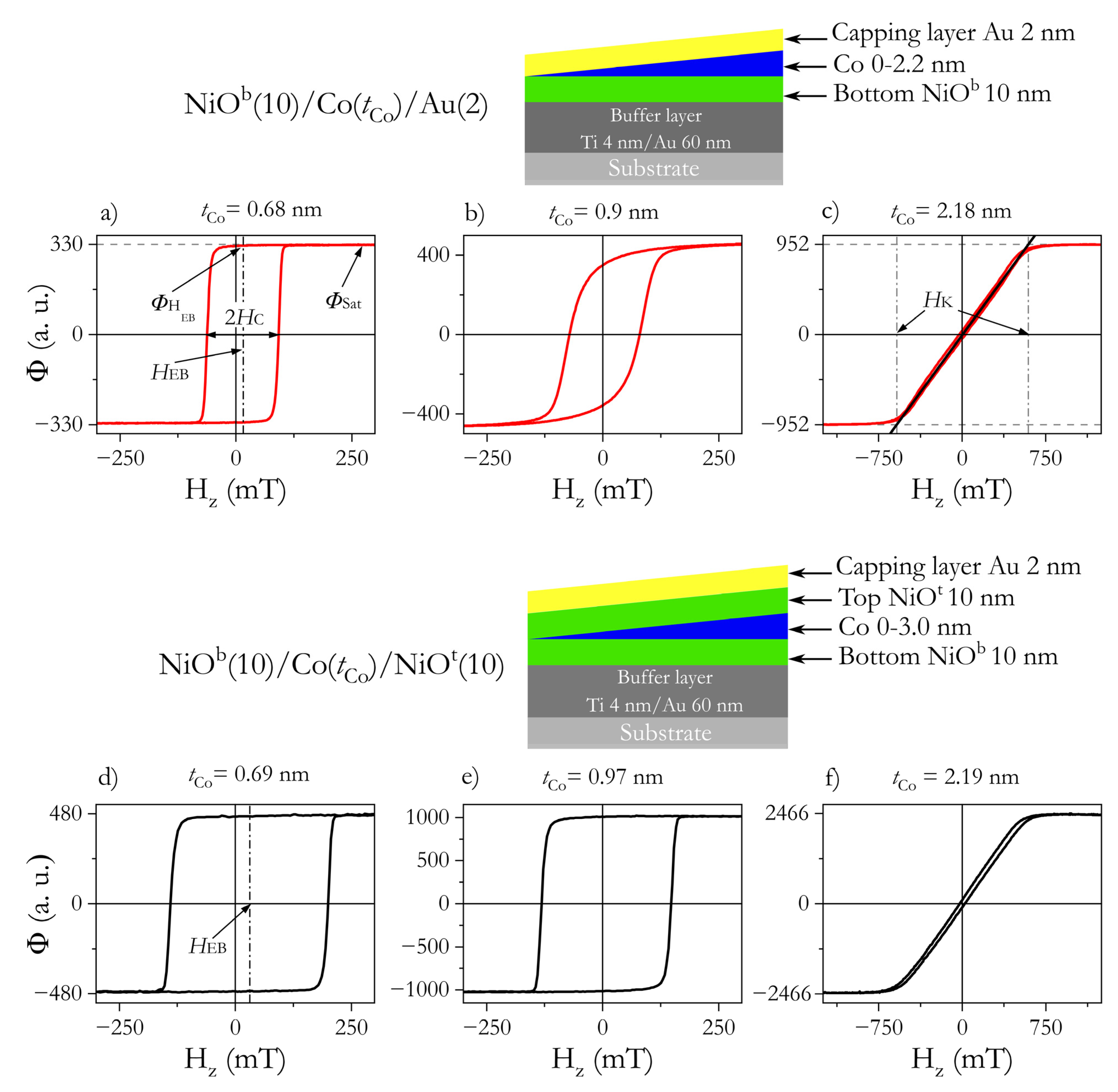
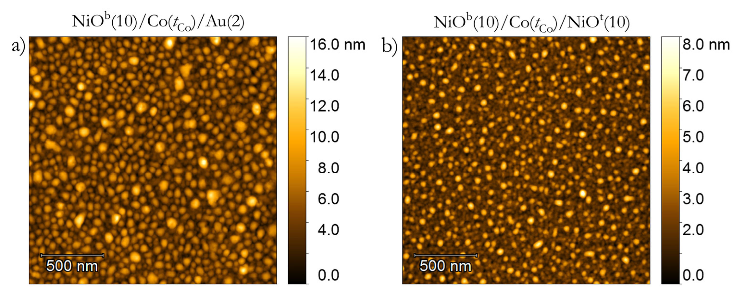
3.1. Magnetic Properties of NiOb/Co/Au and NiOb/Co/NiOt Systems in As-Deposited State

Figure 1 shows three representative PMOKE hysteresis loops for both investigated systems measured at different t Co . For thin Co layers, the rectangular shape of hysteresis loops with ϕ H EB / ϕ Sat = 1 ( ϕ H EB and ϕ Sat are PMOKE signals at H EB and saturation, respectively) (Figure 1a,d,e) shows that both systems exhibit PMA. In the case of NiOb/Co/Au with t Co slightly below SRT, the loop shape suggests (Figure 1b) that a small in-plane magnetization component exists at remanence. In all cases, a positive H EB (the hysteresis loop shift from H z = 0 is opposite to H dep ) is also clearly visible, indicating that the EB coupling is parallel to H dep . For thicker Co, the system undergoes SRT and exhibits EPA (Figure 1c,f).
Before comparing results for the entire t Co range, it should be emphasized that the dependence of the PMOKE signals versus t Co (ϕ( t Co )) of NiOb/Co/NiOt are shifted by about Δ t Co = 0.26 nm with respect to NiOb/Co/Au and Au/Co/Au systems [36]. We have previously shown that the deposition of the NiO layer in an oxygen-rich atmosphere results in the formation of a thin CoO layer between Co and NiO at the Co/NiOt interface [36,37]. The samples in this report were deposited in the same conditions; therefore, a similar CoO layer should form in NiOb/Co/NiOt. Comparisons of the present data with the NiOb/Co/Au and Au/Co/Au systems should be based on the real Co thickness (without CoO); therefore, the data in this paper were adjusted based on Δ t Co determined above.
From the analysis of hysteresis loops for NiOb/Co/Au, we distinguished three important thickness ranges: (I) for 0.5 nm < t Co ≤ 0.75 nm, the hysteresis loops are rectangular with sharp corners and ϕ H EB / ϕ Sat ≈ 1 (Figure 2a). This is typical of systems with strong PMA in which magnetization reversal takes place by domain nucleation followed by rapid propagation of domain walls [38,39]; (II) for 0.75 nm < t Co < 0.93 nm, the shape of the hysteresis loops ( ϕ H EB / ϕ Sat < 1, Figure 1b) indicates that the activation of multiple nucleation centers defines the reversal process [39]. This also suggests that there is a small in-plane magnetization component at remanence; (III) at t Co = 0.93 nm, the system undergoes SRT (see Figure 3); and as t Co , grows further, the magnetization reversal process approaches that of coherent magnetization rotations for EPA (Figure 1c).
A similar result was obtained for NiOb/Co/NiOt, with SRT happening at a slightly thicker Co layer ( t Co = 1 nm) (see Figure 3). For this system, the transition from PMA to EPA appears more abruptly for NiOb/Co/Au, where it extends over a much greater t Co range (Figure 2a). This means that the squareness of the hysteresis loops improves (Figure 1e) when the Co layer is coupled with NiO on both sides (like in ref. [27]). A rectangular loop with sharp corners occurs when the nucleation energy significantly exceeds the energy of DW propagation, and the nucleation energies do not show a significant distribution of values in the sample plane [38]. As the difference between these energies decreases and the dispersion of the nucleation energy increases, the magnetization reversal process will evolve from a situation where it occurs through the creation of a few domains and rapid propagation of DW to a situation where nucleation processes take place in many places at different values of the magnetic field. Since the effect on Co out-of-plane anisotropy is stronger in the Co/NiOt than in the Co/Au interface (this will be discussed later), we attribute the distinct magnetization reversal close to SRT to a higher magnetic anisotropy of the NiOb/Co/NiOt system. We should also emphasize that the magnetization reversal process close to SRT can also be influenced by the relation between second- and first-order magnetic anisotropy [40]. Since, for the HM/Co/Oxide systems, the second-order magnetic anisotropy can be large [41,42], this anisotropy might be a source of wider t Co transition range from PMA to EPA for NiOb/Co/Au than for NiOb/Co/NiOt. An understanding of the role of second-order magnetic anisotropy in both systems needs further investigation.
For both systems (which show polycrystalline structure (Figure 4) with grain sizes below 52 nm for NiOb/Co/Au and below 32 nm for NiOb/Co/NiOt), we found the typical behavior of the EB effect; that is, H EB is inversely proportional to t Co (Figure 2c). This reveals that the strong EB coupling is present on both Co/NiOt and NiOb/Co interfaces. The most significant difference between our systems in the as-deposited state is related to the values of H C and H EB (Figure 2b,c): for NiOb/Co/NiOt, H C and the H EB fields are almost two times larger than those of NiOb/Co/Au and Au/Co/NiO [36]. This indicates that EB coupling is a sum from both interfaces in NiOb/Co/NiOt, showing the additive nature of this coupling. Sort et al. [27] reached the same conclusion in their investigations of AFM/FM/AFM systems. In contrast to that work, our study focuses on the additive nature of EB coupling with variable FM thickness. This results in high values of magnetic properties important for applications, e.g., H C , max = 171 mT at t Co = 0.83 nm and H EB , max = 45 mT at t Co = 0.55 nm for NiOb/Co/NiOt system.
We now proceed to confirm the origin of the PMA using values of surface ( K S ) and volume ( K V ) contributions to effective anisotropy ( K eff ). Anisotropy field values ( H K ) are determined from PMOKE hysteresis loops (Figure 1c,f) for Co thicknesses above the SRT. Then, K eff is calculated using:
K eff = μ 0 M S H K 2
where μ 0 is the vacuum permeability and M S is the saturation magnetization of bulk Co. Here, we compare the data with similar Au/Co/Au and Au/Co/NiO systems; therefore, we assume the same saturation magnetization M S = 1.42 × 10⁶ A/m [36]. Linear fits using K eff t Co   =   2 K S   +   K V t Co and K eff t Co data (Figure 3) provide the values for K S and K V , as summarized in Table 2.
The data in Table 2 show that the surface contribution (2 K S ) to the effective anisotropy on both of our systems is similar to those on Au/Co/Au [2,36,43] and on Pt/Co/Pt [2,3]. In comparison with HM/Co/Oxide systems, our values are two times smaller [44,45]; however, after low-temperature annealing during the FC procedure, these values increase significantly (see Figure 5e and Figure 6e), similar to what was found in Ref. [44]. Note that a direct comparison of individual surface contributions to PMA from the Co/oxide interfaces is quite difficult because typical studies of oxide interface effects on PMA are performed for HM/Co/oxide systems, where the FM layer is adjacent to HM (e.g., Au, Pt, Pd), providing high interface anisotropy [2,3]. To get information about K S for the Co/oxide interface, the contribution from HM/Co must be subtracted from 2 K S and it is usually determined from symmetrical HM/Co/HM systems with the assumption that both HM/Co and Co/HM interfaces are identical and contribute equally to surface anisotropy. Hence, the determination of these values is often approximated under this assumption. Nevertheless, the NiOb/Co/NiOt data clearly show that the AFO/FM (FM/AFO) interface is a source of PMA, with K S of a similar order of magnitude to those of HM/FM.
If the NiOt gives a higher K S than Au [36], the 2 K S value should be higher for NiOb/Co/NiOt than for NiOb/Co/Au. Indeed, this is the case for our studies (Table 2). A larger 2 K S also explains the shift of the SRT to larger t Co (Table 2). Note that, for the NiOb/Co/Au and NiOb/Co/NiOt systems, the KV values are identical and equal to the sum of shape anisotropy for Co thin films (−1/2 μ 0 M S 2 = −1.27 MJ/m3) and magnetocrystalline anisotropy for the hexagonal structure of Co (0.53 MJ/m3) [2]. This indicates that magnetocrystalline anisotropy enhances PMA when Co is deposited on a NiO layer; however, we cannot exclude additional contribution to the K V , e.g., from magnetoelastic anisotropy. It should be emphasized that to date, the PMA has been investigated mainly in HM/FM/oxide systems, where a strong Co/HM surface anisotropy also helps to stabilize the PMA. Here, we demonstrate that HM is not necessary to stabilize PMA at RT, which offers a new type of multilayer system with strong PMA.

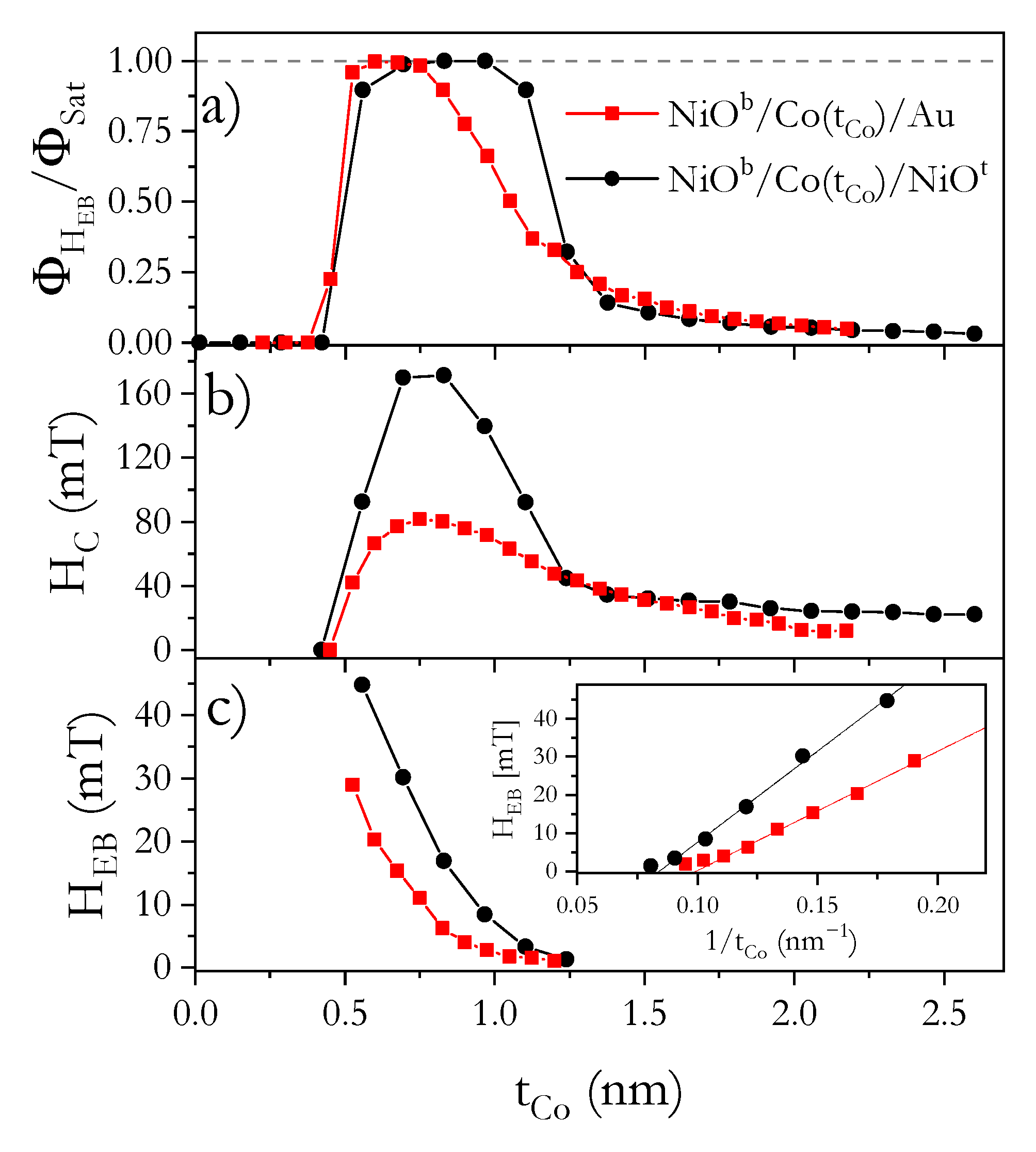
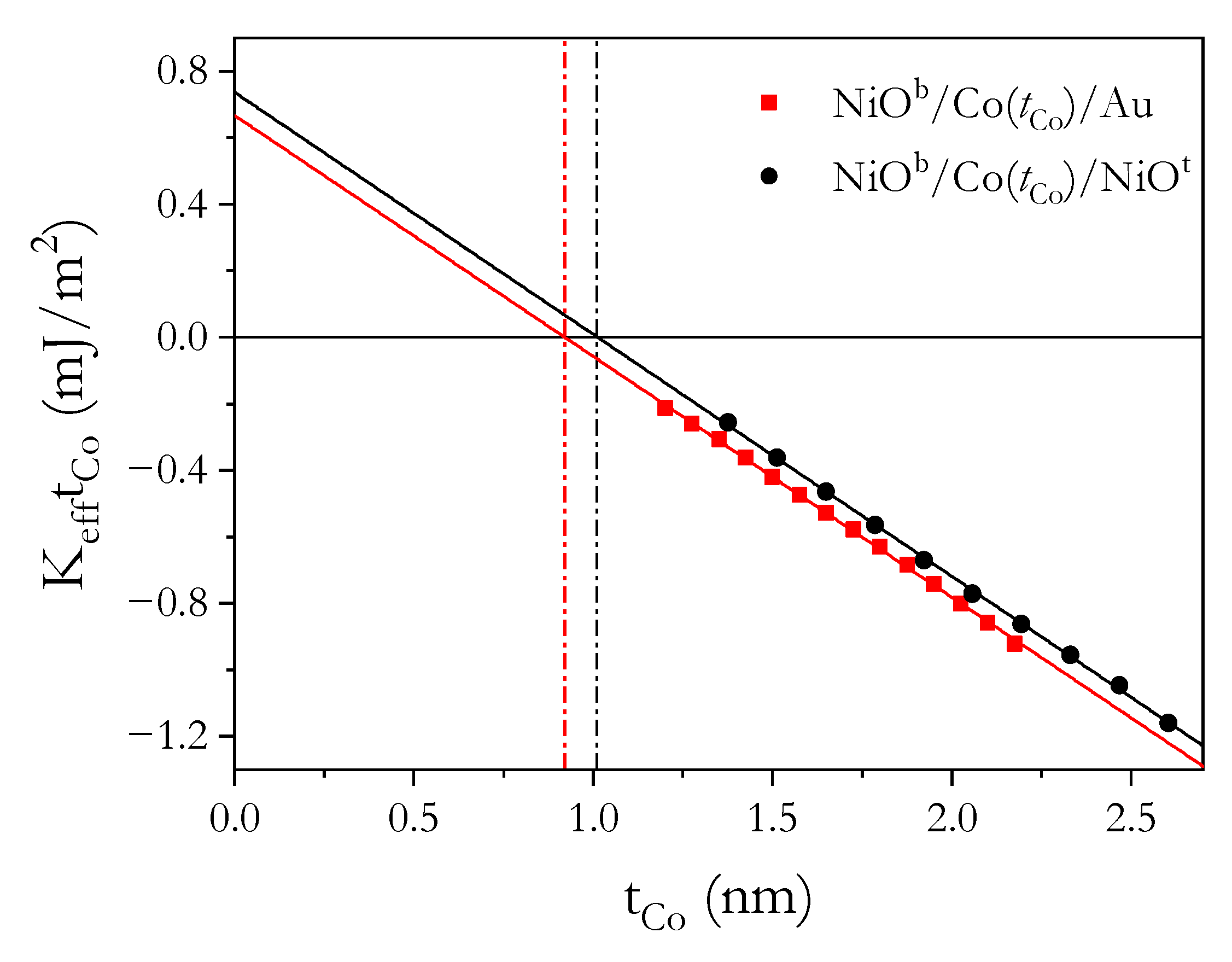
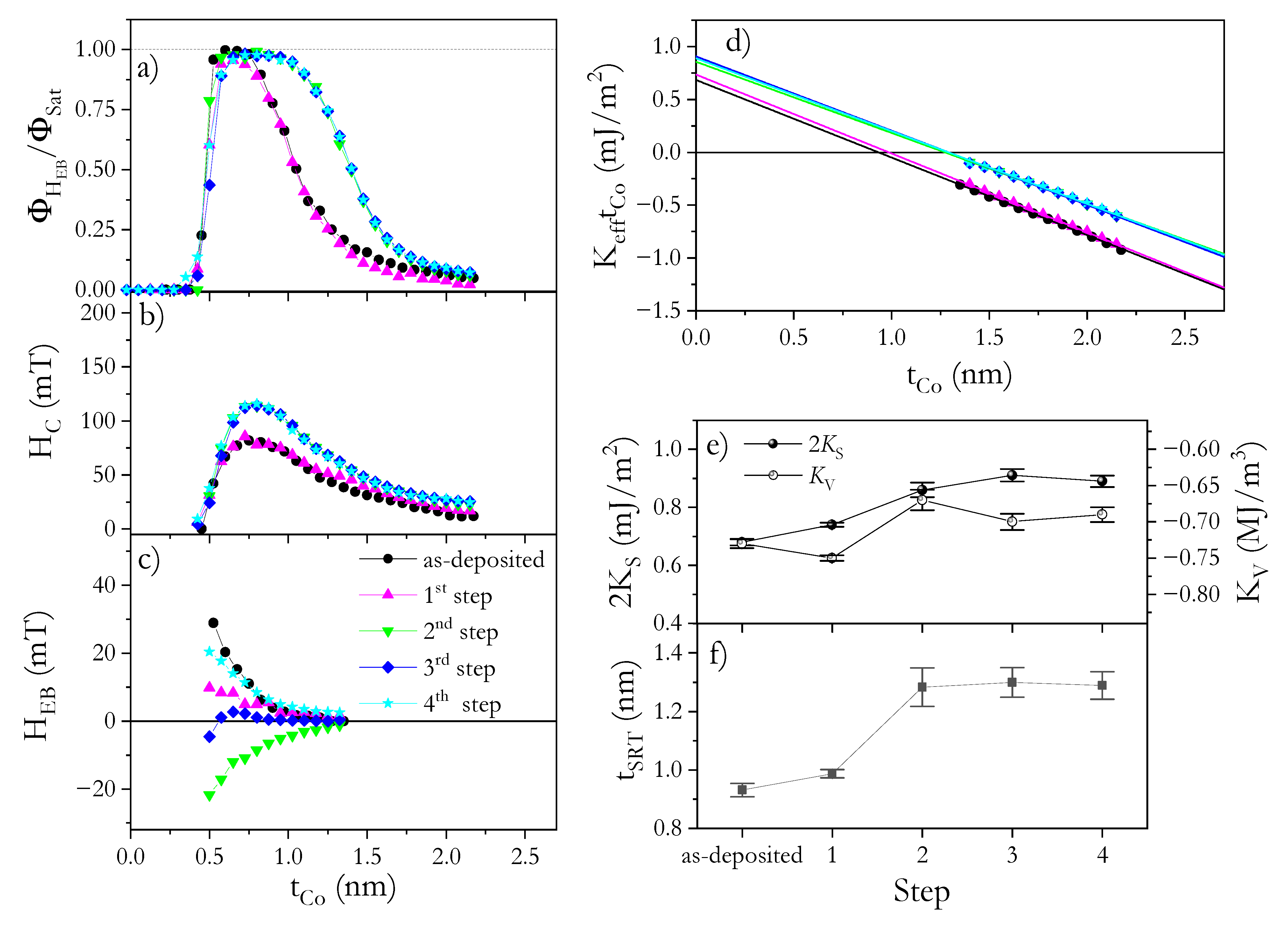
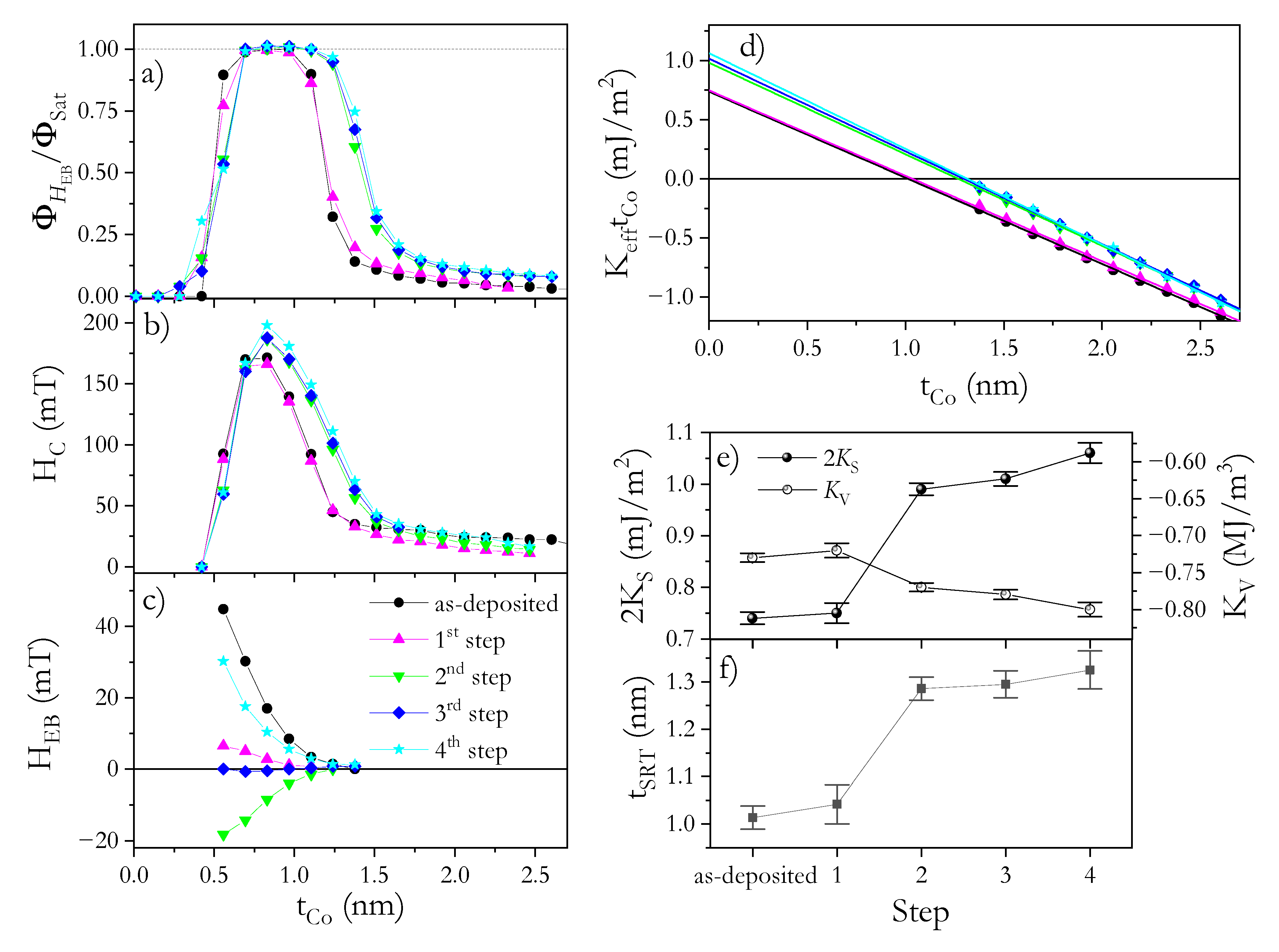
3.2. Magnetic Properties of NiOb/Co/Au and NiOb/Co/NiOt Systems after Different FC Steps

To tune the EB coupling, the NiOb/Co/Au and NiOb/Co/NiOt systems underwent the four FC steps described above (see Table 1 in the Experiment section). After the first FC step ( T FC = 350 K in H FC = +170 mT), the H EB reduces significantly (Figure 5c and Figure 6c) but coercivity (Figure 5b and Figure 6b) and effective anisotropy (Figure 5d and Figure 6d) maintain their high values for both systems. Note that the direction of H FC is opposite to the direction of H dep . One would expect a flip in the EB coupling direction for FC processes starting at T FC higher than the Néel (blocking) temperature T N ( T B ). This is not observed in our case, although H EB experiences a significant decrease. In the analysis of polycrystalline samples (Figure 4), the AFM layer is usually treated as a set of magnetically noninteracting grains with a size distribution that spreads the T B [46,47]. Therefore, grains with T B < T FC lose their AFM pinning strength and, during the FC procedure, the pinning direction may reverse from the initial direction set by H dep to the direction parallel to H FC . For NiOb/Co/Au, this means that part of the grain is coupled along H FC and part along H dep (i.e., in opposite directions), and as a result, the effective H EB is strongly reduced.
In the case of NiOb/Co/NiOt, we need to consider EB effect contributions from two interfaces simultaneously (NiO/Co and Co/NiOt), and the fact that EB couplings at each interface are too weak to introduce rotation of the Co spin across the film thickness if the EB coupling direction at both interfaces is opposite. This is due to the small thickness and higher exchange and anisotropy energies than EB coupling energy. Since after the first step of FC we found that the H EB for NiOb/Co/Au is slightly larger than for NiOb/Co/NiOt, many more grains at the Co/NiOt interface are coupled along H FC than at the NiOb/Co interface. This means that the grains of NiOb show a lower blocking temperature than NiOt, which can be correlated with CoO at the Co/NiOt interface, which reduces the ordering (blocking) temperature of NiO [48]. It should be emphasized that, at this low annealing temperature (350 K), only H EB changes significantly, showing that annealing below 350 K can be used to tune this parameter without altering magnetic anisotropy.
To couple even more grains, a second FC step was applied starting from a higher temperature ( T FC = 450 K) and with the same value and direction of H FC (+170 mT). In this step, we expected that the temperature was high enough to align the EB coupling of many more grains with H FC for both systems. Indeed, H EB became highly negative (Figure 5c and Figure 6c), indicating a strongly effective EB. However, the magnitude of H EB was smaller, especially for NiOb/Co/NiOt, than for the as-deposited state, which could have been caused by interface modification during annealing. This statement also supports an additional observation: the SRT occurs at a larger t Co (Figure 5d,f and Figure 6d,f), and the corresponding increase in PMA (Figure 5d and Figure 6d) correlates with an increase in H C (Figure 5b and Figure 6b). Therefore, at this step, irreversible changes in the microstructure take place, which are stable for further annealing up to 450 K (see Figure 5 and Figure 6 for 3rd and 4th steps). Since the second FC process did not result in the shift of t Co where PMA starts to appear (Figure 5a and Figure 6b), and we do not detect any additional shift of ϕ Sat ( t Co ) dependence, we assume that there is no further oxidation of the Co layer and therefore the anisotropy changes are not related to reductions in t Co . Note that for both systems, K V almost does not change ( K V = 0.67 MJ/m3 and K V = 0.77 MJ/m3 for NiOb/Co/Au and NiOb/Co/NiOt systems, respectively) (Figure 5e and Figure 6e); therefore, additional oxidation of Co layer can be excluded after the FC process. Thus, the increase in PMA is attributed to interface morphology modifications because 2 K S increases to 0.86 mJ/m2 for NiOb/Co/Au (Figure 5e) and to 0.99 mJ/m2 NiOb/Co/NiOt (Figure 6e). A similar increase in K S was shown for HM/Co/oxide systems after annealing, which was attributed to homogeneous oxidation along the interface and to interface smoothening [44]. Considering that this type of interface modification might be a source of smaller H EB [49] and that 2 K S increase less for the NiOb/Co/Au system than for NiOb/Co/NiOt, we expect that the changes on the Co/NiOt interface are greater than those on the NiOb/Co interface, which may be a source of the lower H EB for NiOb/Co/NiOt.
The last two FC steps described in Table 1 help us to understand the effects of PMA enhancement on EB coupling. After these steps, for both systems, neither effective magnetic anisotropy (Figure 5d–f and Figure 6d–f) ( K S and K V , and t SRT ) nor H C show significant changes. This means that strong interface modifications caused by annealing at T ≤ 450 K have ceased, and the reversible H EB changes in the 3rd and 4th step can be repeated without altering other magnetic properties.
Note that in the 4th step, the H FC is aligned in the same direction as H dep , therefore we should expect that pinning directions from all NiOb and NiOt grains are aligned in the same direction giving a high H EB effect. Indeed, these values are high; however, H EB is smaller than that observed for the as-deposited state, which we attribute to a smaller contribution to effective EB field from Co/NiOt appearing after the 2nd step of the FC process. Nevertheless, H EB and H C for NiOb/Co/NiOt (Figure 6b,c) are still much higher than for NiOb/Co/Au (Figure 5b,c) showing additive nature of EB coupling. All that shows that a carefully chosen AFM–FM system offers simultaneous support for a strong PMA and high H EB , which can be tuned over a wide range by the proper selection of an FC procedure.

4. Conclusions

In summary, the EB coupling in NiO/Co and Co/NiO interfaces has been investigated in terms of perpendicular magnetic anisotropy and EB field. Using NiO/Co/Au and NiO/Co/NiO systems, we have shown that the CoNiO interface induces strong surface contribution to the effective magnetic anisotropy, favoring out-of-plane magnetization of Co layer. We also demonstrate that strong perpendicular magnetic anisotropy can be achieved by using only AFO-FM interfaces, where the EB field can be modified over a wide range by proper selection of field cooling conditions. The presence of two interfaces, NiO/Co and Co/NiO, in a NiO/Co/NiO system allows us to reach high H C and H EB because each interface simultaneously supports EB coupling and PMA. These results establish that a new multilayer system based on antiferromagnetic oxides offers strong PMA and the ability to tune H EB and H C in a wide range, which are important qualities for spintronic applications.

Author Contributions

Conceptualization, P.K. and M.K.; methodology (samples preparation), B.A. and M.S.; samples validation, B.A. and M.S.; visualization, M.K.; investigation, M.K.; supervision, P.K.; resources P.K. and F.S.; writing—original draft preparation, M.K. and P.K.; writing—review and editing, F.S. All authors have read and agreed to the published version of the manuscript.

Funding

This work was supported by the National Science Centre, Poland under SONATA-BIS funding (Grant No. UMO-2015/18/E/ST3/00557). B.A. acknowledges support from the project “Środowiskowe interdyscyplinarne studia doktoranckie w zakresie nanotechnologii” POWR.03.02.00-00-I032/16.

Institutional Review Board Statement

Not applicable.

Informed Consent Statement

Not applicable.

Data Availability Statement

The data presented in this study are available on request from the corresponding author.

Conflicts of Interest

The authors declare no conflict of interest.

References

  1. Spörl, K.; Weller, D. Interface anisotropy and chemistry of magnetic multilayers: Au/Co, Pt/Co and Pd/Co. J. Magn. Magn. Mater. 1991, 93, 379–385. [Google Scholar] [CrossRef]
  2. Johnson, M.T.; Bloemen, P.J.H.; Broeder, F.J.A.D.; De Vries, J.J. Magnetic anisotropy in metallic multilayers. Rep. Prog. Phys. 1996, 59, 1409–1458. [Google Scholar] [CrossRef]
  3. Broeder, F.D.; Hoving, W.; Bloemen, P. Magnetic anisotropy of multilayers. J. Magn. Magn. Mater. 1991, 93, 562–570. [Google Scholar] [CrossRef]
  4. Néel, L. Anisotropie magnétique superficielle et surstructures d’orientation. J. Phys. 1954, 15, 225–239. [Google Scholar] [CrossRef]
  5. Piramanayagam, S.N. Perpendicular recording media for hard disk drives. J. Appl. Phys. 2007, 102, 011301. [Google Scholar] [CrossRef]
  6. Meiklejohn, W.H.; Bean, C.P. New Magnetic Anisotropy. Phys. Rev. 1957, 105, 904–913. [Google Scholar] [CrossRef]
  7. Meiklejohn, W.H. Exchange Anisotropy—A Review. J. Appl. Phys. 1962, 33, 1328–1335. [Google Scholar] [CrossRef]
  8. Maat, S.; Takano, K.; Parkin, S.S.P.; Fullerton, E.E. Perpendicular exchange bias ofCo/Ptmultilayers. Phys. Rev. Lett. 2001, 87, 087202. [Google Scholar] [CrossRef]
  9. Ikeda, S.; Miura, K.T.; Yamamoto, H.; Mizunuma, K.; Gan, H.D.; Endo, M.; Kanai, S.; Hayakawa, J.; Matsukura, F.; Ohno, H. A perpendicular-anisotropy CoFeB–MgO magnetic tunnel junction. Nat. Mater. 2010, 9, 721–724. [Google Scholar] [CrossRef]
  10. Schott, M.; Bernand-Mantel, A.; Ranno, L.; Pizzini, S.; Vogel, J.; Béa, H.; Baraduc, C.; Auffret, S.; Gaudin, G.; Givord, D. The skyrmion switch: Turning magnetic skyrmion bubbles on and off with an electric field. Nano Lett. 2017, 17, 3006–3012. [Google Scholar] [CrossRef] [PubMed] [Green Version]
  11. Boulle, O.; Vogel, J.; Yang, H.; Pizzini, S.; Chaves, D.D.S.; Locatelli, A.; Menteş, T.O.; Sala, A.; Buda-Prejbeanu, L.D.; Klein, O.; et al. Room-temperature chiral magnetic skyrmions in ultrathin magnetic nanostructures. Nat. Nanotechnol. 2016, 11, 449–454. [Google Scholar] [CrossRef] [Green Version]
  12. Mlynczak, E.; Gurgul, J.; Przewoznik, J.; Ślęzak, D.W.; Freindl, K.; Spiridis, N.; Korecki, J. Effect of interfacial iron oxidation on the exchange bias in CoO/Fe bilayers. Appl. Surf. Sci. 2014, 304, 86–90. [Google Scholar] [CrossRef]
  13. Ślęzak, M.; Ślęzak, T.; Dróżdż, P.; Matlak, B.; Matlak, K.; Kozioł-Rachwał, A.; Zając, M.; Korecki, J. How a ferromagnet drives an antiferromagnet in exchange biased CoO/Fe(110) bilayers. Sci. Rep. 2019, 9, 1–8. [Google Scholar] [CrossRef] [Green Version]
  14. Monso, S.; Rodmacq, B.; Auffret, S.; Casali, G.; Fettar, F.; Gilles, B.; Dieny, B.; Boyer, P. Crossover from in-plane to perpendicular anisotropy in Pt/CoFe/AlOx sandwiches as a function of Al oxidation: A very accurate control of the oxidation of tunnel barriers. Appl. Phys. Lett. 2002, 80, 4157–4159. [Google Scholar] [CrossRef]
  15. Rodmacq, B.; Auffret, S.; Dieny, B.; Monso, S.; Boyer, P. Crossovers from in-plane to perpendicular anisotropy in magnetic tunnel junctions as a function of the barrier degree of oxidation. J. Appl. Phys. 2003, 93, 7513. [Google Scholar] [CrossRef]
  16. Yang, H.; Boulle, O.; Cros, V.; Fert, A.; Chshiev, M. Controlling Dzyaloshinskii-Moriya interaction via chirality dependent atomic-layer stacking, insulator capping and electric field. Sci. Rep. 2018, 8, 1–7. [Google Scholar] [CrossRef] [PubMed]
  17. Belabbes, A.; Bihlmayer, G.; Blügel, S.; Manchon, A. Oxygen-enabled control of Dzyaloshinskii-Moriya Interaction in ultra-thin magnetic films. Sci. Rep. 2016, 6, 24634. [Google Scholar] [CrossRef] [PubMed] [Green Version]
  18. Kuświk, P.; Matczak, M.; Kowacz, M.; Szuba-Jabłoński, K.; Michalak, N.; Szymański, B.; Ehresmann, A.; Stobiecki, F. Asymmetric domain wall propagation caused by interfacial Dzyaloshinskii-Moriya interaction in exchange biased Au/Co/NiO layered system. Phys. Rev. B 2018, 97, 024404. [Google Scholar] [CrossRef]
  19. Kuświk, P.; Matczak, M.; Kowacz, M.; Lisiecki, F.; Stobiecki, F. Determination of the Dzyaloshinskii-Moriya interaction in exchange biased Au/Co/NiO systems. J. Magn. Magn. Mater. 2019, 472, 29–33. [Google Scholar] [CrossRef] [Green Version]
  20. Kolesnikov, A.; Stebliy, M.; Davydenko, A.; Kozlov, A.; Osmushko, I.; Korochentsev, V.; Ognev, A.; Gerasimenko, A.; Sadovnikov, A.; Gubanov, V.; et al. Magnetic properties and the interfacial Dzyaloshinskii-Moriya interaction in exchange biased Pt/Co/NixOy films. Appl. Surf. Sci. 2020, 543, 148720. [Google Scholar] [CrossRef]
  21. Guang, Y.; Bykova, I.; Liu, Y.; Yu, G.; Goering, E.; Weigand, M.; Gräfe, J.; Kim, S.K.; Zhang, J.; Zhang, H.; et al. Creating zero-field skyrmions in exchange-biased multilayers through X-ray illumination. Nat. Commun. 2020, 11, 1–6. [Google Scholar] [CrossRef] [PubMed] [Green Version]
  22. Yu, G.; Jenkins, A.; Jiang, W.; Han, X.; Li, X.; Jayich, A.C.B.; Amiri, P.K.; Wang, K.L.; Ma, X.; Razavi, S.A.; et al. Room-temperature skyrmions in an antiferromagnet-based heterostructure. Nano Lett. 2018, 18, 980–986. [Google Scholar] [CrossRef] [PubMed]
  23. Rana, K.G.; Finco, A.; Denneulin, T.; Dunin-Borkowski, R.E.; Gaudin, G.; Jacques, V.; Boulle, O.; Fabre, F.; Chouaieb, S.; Haykal, A.; et al. Room-temperature skyrmions at zero field in exchange-biased ultrathin films. Phys. Rev. Appl. 2020, 13, 044079. [Google Scholar] [CrossRef]
  24. Polenciuc, I.; Vick, A.J.; Allwood, D.A.; Hayward, T.J.; Vallejo-Fernandez, G.; O’Grady, K.; Hirohata, A. Domain wall pinning for racetrack memory using exchange bias. Appl. Phys. Lett. 2014, 105, 162406. [Google Scholar] [CrossRef] [Green Version]
  25. Parkin, S.S.P.; Hayashi, M.; Thomas, L. Magnetic domain-wall racetrack memory. Science 2008, 320, 190–194. [Google Scholar] [CrossRef]
  26. Zhang, Y.; Zhang, X.; Hu, J.; Nan, J.; Zheng, Z.; Zhang, Z.; Zhang, Y.; Vernier, N.; Ravelosona, D.; Zhao, W. Ring-shaped Racetrack memory based on spin orbit torque driven chiral domain wall motions. Sci. Rep. 2016, 6, 35062. [Google Scholar] [CrossRef]
  27. Sort, J.; Dieny, B.; Nogués, J. Exchange bias in antiferromagnetic-ferromagnetic-antiferromagnetic structures with out-of-plane magnetization. Phys. Rev. B 2005, 72, 104412. [Google Scholar] [CrossRef]
  28. Stamps, R.L. Mechanisms for exchange bias. J. Phys. D Appl. Phys. 2000, 33, R247–R268. [Google Scholar] [CrossRef]
  29. Jiang, J.; Xiu, X.; Wen, K.; Cao, W.; He, Y.; Wang, S. Perpendicular magnetic anisotropy of Pd/Co55Mn25Si20/NiO/Pd sputtering films. J. Magn. Magn. Mater. 2020, 505, 166709. [Google Scholar] [CrossRef]
  30. Doudin, B.; Redmond, G.; Gilbert, S.E.; Ansermet, J.-P. Magnetoresistance governed by fluctuations in ultrasmall NI/NIO/Co junctions. Phys. Rev. Lett. 1997, 79, 933–936. [Google Scholar] [CrossRef]
  31. Yang, H.; Yang, S.-H.; Qi, D.-C.; Rusydi, A.; Kawai, H.; Saeys, M.; Leo, T.; Smith, D.J.; Parkin, S.S.P. Negative tunneling magnetoresistance by canted magnetization inMgo/NioTunnel barriers. Phys. Rev. Lett. 2011, 106, 167201. [Google Scholar] [CrossRef] [PubMed] [Green Version]
  32. Wang, H.; Du, C.; Hammel, P.C.; Yang, F. Antiferromagnonic spin transport fromY3Fe5O12into NiO. Phys. Rev. Lett. 2014, 113, 097202. [Google Scholar] [CrossRef] [PubMed] [Green Version]
  33. Głowiński, H.; Lisiecki, F.; Kuświk, P.; Dubowik, J.; Stobiecki, F. Influence of adjacent layers on the damping of magnetization precession in CoxFe100-x films. J. Alloy. Compd. 2019, 785, 891–896. [Google Scholar] [CrossRef]
  34. Moriyama, T.; Takei, S.; Nagata, M.; Yoshimura, Y.; Matsuzaki, N.; Terashima, T.; Tserkovnyak, Y.; Ono, T. Anti-damping spin transfer torque through epitaxial nickel oxide. Appl. Phys. Lett. 2015, 106, 162406. [Google Scholar] [CrossRef] [Green Version]
  35. Wei, L.; Hu, Z.; Zheng, R.; Hu, Y.; Du, J.; Du, G.; Yuan, Y.; Wang, J.; Tu, H.; You, B.; et al. Full electric control of exchange bias at room temperature by resistive switching. Adv. Mater. 2018, 30. [Google Scholar] [CrossRef]
  36. Kuświk, P.; Szymański, B.; Anastaziak, B.; Matczak, M.; Urbaniak, M.; Ehresmann, A.; Stobiecki, F. Enhancement of perpendicular magnetic anisotropy of Co layer in exchange-biased Au/Co/NiO/Au polycrystalline system. J. Appl. Phys. 2016, 119, 215307. [Google Scholar] [CrossRef]
  37. Grochot, K.; Karwacki, Ł.; Łazarski, S.; Skowroński, W.; Kanak, J.; Powroźnik, W.; Kuświk, P.; Kowacz, M.; Stobiecki, F.; Stobiecki, T. Current-induced magnetization switching of exchange-biased NiO heterostructures characterized by spin-orbit torque. Phys. Rev. Appl. 2021, 15, 014017. [Google Scholar] [CrossRef]
  38. Jamet, J.-P.; Lemerle, S.; Meyer, P.; Ferré, J.; Bartenlian, B.; Bardou, N.; Chappert, C.; Veillet, P.; Rousseaux, F.; Decanini, D.; et al. Dynamics of the magnetization reversal in Au/Co/Au micrometer-size dot arrays. Phys. Rev. B 1998, 57, 14320–14331. [Google Scholar] [CrossRef]
  39. Pommier, J.; Meyer, P.; Pénissard, G.; Ferré, J.; Bruno, P.; Renard, D. Magnetization reversal in ultrathin ferromagnetic films with perpendicular anistropy: Domain observations. Phys. Rev. Lett. 1990, 65, 2054–2057. [Google Scholar] [CrossRef]
  40. Kisielewski, M.; Tekielak, M.; Wawro, A.; Baczewski, L.T.; Maziewski, A. New possibilities for tuning ultrathin cobalt film magnetic properties by a noble metal overlayer. Phys. Rev. Lett. 2002, 89, 087203. [Google Scholar] [CrossRef] [PubMed]
  41. Gweon, H.K.; Lim, S.H. Evolution of strong second-order magnetic anisotropy in Pt/Co/MgO trilayers by post-annealing. Appl. Phys. Lett. 2020, 117, 082403. [Google Scholar] [CrossRef]
  42. Gweon, H.K.; Park, H.-J.; Kim, K.-W.; Lee, K.-J.; Lim, S.H. Intrinsic origin of interfacial second-order magnetic anisotropy in ferromagnet/normal metal heterostructures. NPG Asia Mater. 2020, 12, 1–6. [Google Scholar] [CrossRef] [Green Version]
  43. Kuświk, P.; Stobiecki, F.; Szymański, B.; Urbaniak, M.; Falkowski, M.; Jagielski, J.; Mazalski, P. Effect of He ions irradiation on anisotropy and magnetoresistance of (NiFe/Au/Co/Au)10 multilayers. Nucl. Instr. Met. Phys. Res. Sect. B Beam Interact. Mater. Atoms 2012, 272, 88–91. [Google Scholar] [CrossRef]
  44. Dieny, B.; Chshiev, M. Perpendicular magnetic anisotropy at transition metal/oxide interfaces and applications. Rev. Mod. Phys. 2017, 89, 025008. [Google Scholar] [CrossRef]
  45. Chen, X.; Feng, C.; Wu, Z.L.; Yang, F.; Liu, Y.; Jiang, S.; Li, M.H.; Yu, G.H. Interfacial oxygen migration and its effect on the magnetic anisotropy in Pt/Co/MgO/Pt films. Appl. Phys. Lett. 2014, 104, 052413. [Google Scholar] [CrossRef]
  46. Ehresmann, A.; Junk, D.; Engel, D.; Paetzold, A.; Roll, K. On the origin of ion bombardment induced exchange bias modifications in polycrystalline layers. J. Phys. D Appl. Phys. 2005, 38, 801–806. [Google Scholar] [CrossRef]
  47. Kuświk, P.; Gaul, A.; Urbaniak, M.; Schmidt, M.; Aleksiejew, J.; Ehresmann, A.; Stobiecki, F. Tailoring perpendicular exchange bias coupling in AU/Co/NiO systems by Ion bombardment. Nanomaterials 2018, 8, 813. [Google Scholar] [CrossRef] [PubMed] [Green Version]
  48. Takano, M.; Terashima, T.; Bando, Y.; Ikeda, H. Neutron diffraction study of artificial CoO-NiO superlattices. Appl. Phys. Lett. 1987, 51, 205–206. [Google Scholar] [CrossRef]
  49. Kuch, W.; Chelaru, L.I.; Offi, F.; Wang, J.; Kotsugi, M.; Kirschner, J. Tuning the magnetic coupling across ultrathin antiferromagnetic films by controlling atomic-scale roughness. Nat. Mater. 2006, 5, 128–133. [Google Scholar] [CrossRef] [PubMed]
Figure 1. Morphology of samples and representative PMOKE hysteresis loops for the NiOb/Co-wedge/Au system: (a) t Co = 0.68 nm, (b) t Co = 0.9 nm, (c) t Co = 2.18 nm and for the NiOb/Co-wedge/NiOt system: (d) t Co = 0.69 nm, (e) t Co = 0.97 nm, (f) t Co = 2.19 nm.
Materials 14 01237 g001
Figure 2. Dependence of normalized Kerr signal ( ϕ H EB / ϕ Sat ) at H = H EB (a), coercivity ( H C ) (b) and exchange bias fields ( H EB ) (c) on Co layer thickness ( t Co ) for NiOb/Co/Au and NiOb/Co/NiOt systems. Inset in (c) shows H EB (1/ t Co ) dependence.
Materials 14 01237 g002
Figure 3. K eff t Co vs. t Co for NiOb/Co/Au and NiOb/Co/NiOt systems in the as-deposited state. The dashed lines indicate Co thickness corresponding to spin reorientation transition ( t SRT = −2 K S / K V ).
Materials 14 01237 g003
Figure 4. Surface topography measured by atomic force microscope of the as-deposited (a) NiOb/Co-wedge/Au system at t Co = 1 nm and (b) the NiOb/Co-wedge/NiOt system at t Co = 1 nm.
Materials 14 01237 g004
Figure 5. Normalized Kerr signal ( ϕ H EB / ϕ Sat ) at H = H EB (a), coercivity ( H C ) (b) and exchange bias field ( H EB ) (c) as functions of Co layer thickness for NiOb/Co/Au. Product of effective magnetic anisotropy and Co thickness ( K eff t Co ) as a function of t Co (d) for NiOb/Co/Au in the as-deposited state and after different FC steps. Volume and surface anisotropy constants (e) and SRT thickness (f) for NiOb/Co/Au in the as-deposited state and after four different FC steps (1st—350 K, +170 mT; 2nd—450 K, +170 mT; 3rd—350 K, −170 mT; 4th—450 K, −170 mT).
Materials 14 01237 g005
Figure 6. Normalized Kerr signal ( ϕ H EB / ϕ Sat ) at H = H EB (a), coercivity ( H C ) (b) and exchange bias field ( H EB ) (c) as functions of Co layer thickness for NiOb/Co/NiOt. Product of effective magnetic anisotropy and Co thickness ( K eff t Co ) as a function of t Co (d) for NiOb/Co/NiOt in the as-deposited state and after different FC steps. Volume and surface anisotropy constants (e) and SRT thickness (f) for NiOb/Co/NiOt in the as-deposited state and after four different FC steps (1st—350 K, +170 mT; 2nd—450 K, +170 mT; 3rd—350 K, −170 mT; 4th—450 K, −170 mT).
Materials 14 01237 g006
Table 1. Combinations of heating temperatures and signs of H FC for each field cooling (FC) step.
Steps T FC (K) H FC (mT)
1st350+170
2nd450+170
3rd350−170
4th450−170
Table 2. Volume and surface anisotropy constants ( K V , K S ) and t Co at SRT thickness ( t SRT ) for NiOb/Co/Au and NiOb/Co/NiOt in the as-deposited state.
System K V (MJ/m3) 2 K S (mJ/m2) t SRT (nm)
NiOb/Co/Au−0.73 ± 0.010.68 ± 0.010.93 ± 0.01
NiOb/Co/ NiOt−0.73 ± 0.010.74 ± 0.011.01 ± 0.01
Au/Co/Au [36]−0.580.651.12
Au/Co/NiO/Au [36]−1.061.41.32
Publisher’s Note: MDPI stays neutral with regard to jurisdictional claims in published maps and institutional affiliations.

