
Melt-Spun Fibers from Bio-Based Polyester–Fiber Structure Development in High-Speed Melt Spinning of Poly(ethylene 2,5-furandicarboxylate) (PEF)

 , and
, and 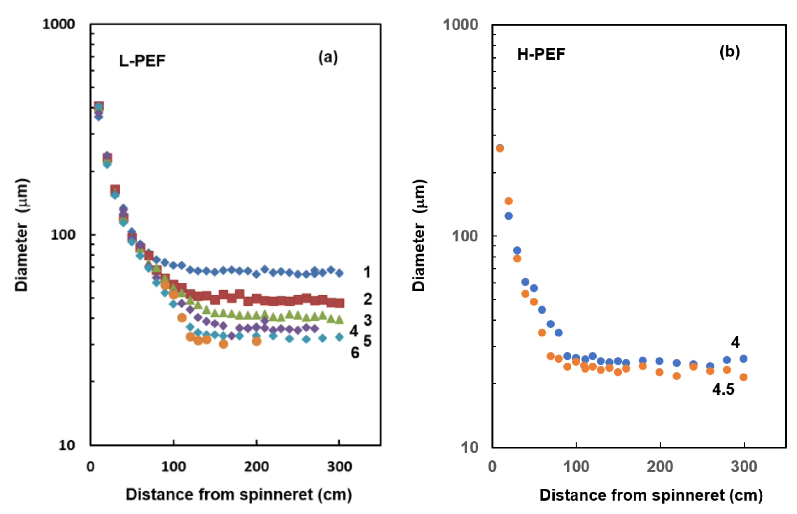
Abstract
1. Introduction
2. Materials and Methods
2.1. Preparation of Fibers
2.1.1. Highspeed Melt Spinning
2.1.2. Drawing and Annealing
2.2. Characterization of the Obtained Fibers
2.2.1. Birefringence
2.2.2. Tensile Test
2.2.3. Wide Angle X-ray diffraction (WAXD)
3. Results and Discussion
3.1. Diameter Profile of Spin-Line
3.2. WAXD Intensity Profile
3.3. Mechanical Properties
4. Conclusions
Author Contributions
Funding
Institutional Review Board Statement
Informed Consent Statement
Data Availability Statement
Conflicts of Interest
References
- Codou, A.; Moncel, M.; van Berkel, J.G.; Guigoa, N.; Sbirrazzuoli, N. Glass transition dynamics and cooperativity length of poly(ethylene 2,5-furandicarboxylate) compared to poly(ethylene terephthalate). Phys. Chem. Chem. Phys. 2016, 18, 16647–16658. [Google Scholar] [CrossRef] [PubMed]
- Burgess, S.K.; Kriegel, R.M.; Koros, W.J. Carbon Dioxide Sorption and Transport in Amorphous Poly(ethylene furanoate). Macromolecules 2015, 48, 2184–2193. [Google Scholar] [CrossRef]
- Burgess, S.K.; Karvan, O.; Johnson, J.R.; Kriegel, R.M.; Koros, W.J. Oxygen sorption and transport in amorphous poly(ethylene furanoate). Polymer 2014, 55, 4748–4756. [Google Scholar] [CrossRef]
- Burgess, S.K.; Mikkilineni, D.S.; Yu, D.B.; Kim, D.J.; Mubarak, C.R.; Kriegel, R.M.; Koros, W.J. Water sorption in poly(ethylene furanoate) compared to poly(ethylene terephthalate). Part 1: Equilibrium sorption. Polymer 2014, 55, 6861–6869. [Google Scholar] [CrossRef]
- Sun, L.; Wang, J.; Mahmud, S.; Jiang, Y.; Zhu, J.; Liu, X. New insight into the mechanism for the excellent gas properties of poly(ethylene 2,5-furandicarboxylate) (PEF): Role of furan ring’s polarity. Eur. Polym. J. 2019, 118, 642–650. [Google Scholar] [CrossRef]
- Gruter, G.-J. The bio-based transition: Drop-in versus new products (1). Chem. Today 2017, 35, 66–67. [Google Scholar]
- Gruter, G.-J. The bio-based transition: Drop-in versus new products (2). Chem. Today 2017, 35, 61–62. [Google Scholar]
- Codou, A.; Guigo, N.; Berkel, J.G.; de Jong, E.; Sbirrazzuoli, N. Non-isothermal Crystallization Kinetics of Biobased Poly(ethylene 2,5-furandicarboxylate) Synthesized via the Direct Esterification Process. Macromol. Chem. Phys. 2014, 215, 2065–2074. [Google Scholar] [CrossRef]
- Van Berkel, J.G.; Guigo, N.; Kolstad, J.J.; Sipos, L.; Wang, B.; Dam, M.A.; Sbirrazzuoli, N. Isothermal Crystallization Kinetics of Poly (Ethylene 2,5-Furandicarboxylate): Isothermal Crystallization Kinetics of Poly (Ethylene 2,5-Furandicarboxylate). Macromol. Mater. Eng. 2015, 300, 466–474. [Google Scholar] [CrossRef]
- Stoclet, G.; Lefebvre, J.M.; Yeniad, B.; Sart, G.G.d.; de Vos, S. On the strain-induced structural evolution of Poly(ethylene-2,5-furanoate) upon uniaxial stretching: An in-situ SAXS-WAXS study. Polymer 2017, 134, 227–241. [Google Scholar] [CrossRef]
- Menager, C.; Guigo, N.; Martino, L.; Sbirrazzuoli, N.; Visser, H.; Boyer, S.A.E.; Billon, N.; Monge, G.; Combeaud, C. Strain induced crystallization in biobased Poly(ethylene 2,5-furandicarboxylate) (PEF); conditions for appearance and microstructure analysis. Polymer 2018, 158, 364–371. [Google Scholar] [CrossRef]
- Forestier, E.; Combeaud, C.; Guigo, N.; Sbirrazzuoli, N.; Billon, N. Understanding of strain-induced crystallization developments scenarios for polyesters: Comparison of poly(ethylene furanoate), PEF, and poly(ethylene terephthalate), PET. Polymer 2020, 203, 122755. [Google Scholar] [CrossRef]
- Burgess, S.K.; Mubarak, C.R.; Kriegel, R.M.; Koros, W.J. Physical aging in amorphous poly(ethylene furanoate): Enthalpic recovery, density, and oxygen transport considerations. J. Polym. Sci. Part B Polym. Phys. 2015, 53, 389–399. [Google Scholar] [CrossRef]
- Burgess, S.K.; Leisen, J.E.; Kraftschik, B.E.; Mubarak, C.R.; Kriegel, R.M.; Koros, W.J. Chain Mobility, Thermal, and Mechanical Properties of Poly(ethylene furanoate) Compared to Poly(ethylene terephthalate). Macromolecules 2014, 47, 1383–1391. [Google Scholar] [CrossRef]
- Aurélie Bourdet, A.; Araujo, S.; Thiyagarajan, S.; Delbreilh, L.; Esposito, A.; Dargent, E. Molecular mobility in amorphous biobased copolyesters obtained with 2,5- and 2,4-furandicarboxylate acid. Polymer 2021, 213, 123225. [Google Scholar] [CrossRef]
- Araujo, C.F.; Nolasco, M.M.; Ribeiro-Claro, P.J.; Rudić, S.; Silvestre, A.J.; Vaz, P.D.; Sousa, A.F. Inside PEF: Chain Conformation and Dynamics in Crystalline and Amorphous Domains. Macromolecules 2018, 51, 3515–3526. [Google Scholar] [CrossRef]
- Van Berkel, J.G.; Guigo, N.; Visser, H.A.; Sbirrazzuoli, N. Chain Structure and Molecular Weight Dependent Mechanics of Poly(ethylene 2,5-furandicarboxylate) Compared to Poly(ethylene terephthalate). Macromolecules 2018, 51, 8539–8549. [Google Scholar] [CrossRef]
- Dolmans, R.P.L. Evaluation of commercially available biobased polymers in textile filament extrusion. In Dissertation for Doctor of Engineering; RWTH Aachen University: Aachen, Germany, 2014. [Google Scholar]
- Ji, P.; Lu, D.; Zhang, S.; Zhang, W.; Wang, C.; Wang, H. Modification of Poly(Ethylene 2,5-Furandicarboxylate) with Poly(Ethylene Glycol) for Biodegradable Copolyesters with Good Mechanical Properties and Spinnability. Polymers 2019, 11, 2105. [Google Scholar] [CrossRef]
- Kokubun, Y.; Iga, K. Index Profile Measurement of Optical Fibers by Means of a Transverse Interferogram. Trans. IECE 1978, 61, 184–187. [Google Scholar]
- Kikutani, T.; Radhakrishnan, J.; Arikawa, S.; Takaku, A.; Okui, N.; Jin, X.; Niwa, F.; Kudo, Y. High-Speed Melt Spinning of Bicomponent Fibers: Mechanism of Fiber structure Development in Poly(ethylene terephthalate)/Polypropylene System. J. Appl. Polym. Sci. 1996, 62, 1913–1924. [Google Scholar] [CrossRef]
- Shimizu, J.; Okui, N.; Kikutani, T. Simulation of Dynamics and Structure Formation in High-Speed Melt Spinning. In High-Speed Fiber Spinning, 1st ed.; Science and Engineering Aspects; Ziabicki, A., Kawai, H., Eds.; Wiley: New York, NY, USA, 1985; pp. 173–201. [Google Scholar]
- Kikutani, T.; Matsui, T.; Takaku, A.; Shimizu, J. Diameter Measurement in the Vicinity of Neck-like Deformation in High-speed Melt Spinning Process. Sen’i Gakkaishi 1989, 45, 441–446. [Google Scholar] [CrossRef][Green Version]
- Kikutani, T.; Kawahara, Y.; Ogawa, N.; Okui, N. Capturing of Real Image of Neck-Like Deformation from High-Speed Spinning Line. Sen’i Gakkaishi 1994, 50, 561–566. [Google Scholar] [CrossRef][Green Version]
- Kikutani, T.; Nakao, K.; Takarada, W.; Ito, H. On-line Measurement of Orientation Development in the High-Speed Melt Spinning Process. Polym. Eng. Sci. 1999, 39, 2349–2357. [Google Scholar] [CrossRef]
- Miyata, K.; Kikutani, T.; Okui, N. Fiber Structure Formation in Ultra-High-Speed Melt Spinning of Poly(ethylene 2,6-naphthalene dicarboxylate). J. Appl. Polym. Sci. 1997, 65, 1415–1427. [Google Scholar] [CrossRef]
- Shimizu, J.; Okui, N.; Kikutani, T. Finer Structure and Physical Properties of Fibers Melt-Spun at High-speeds from Various Polymers. In High-speed Fiber Spinning, 1st ed.; Science and Engineering Aspects; Ziabicki, A., Kawai, H., Eds.; Wiley: New York, NY, USA, 1985; pp. 429–483. [Google Scholar]
- Kikutani, T.; Wakayama, K.; Sato, M.; Takaku, A. Fiber Structure Formation in High-Speed Melt Spinning of Poly(Phenylene Sulfide). Sen’i Gakkaishi 1992, 48, 549–556. [Google Scholar] [CrossRef][Green Version]
- Murase, Y.; Nagai, A. Melt Spinning. In Advanced Fiber Spinning Technology; Nakajima, T., Kajiwara, K., McIntyre, J.E., Eds.; Woodhead Publishing: Sawston, Cambridge, UK, 1994; pp. 25–64. [Google Scholar]
- Daubeny, R.D.P.; Bunn, C.; Brown, C.J. The crystal structure of polyethylene terephthalate. Proc. R. Soc. Lond. Ser. A 1954, 226, 531–542. [Google Scholar]
- Shimizu, J.; Kikutani, T.; Takaku, A.; Okui, N. Fiber structure formation in high speed melt spinning of poly(ethylene terephthalate)—characterization of fiber structure by considering oriented mesophase. Sen’i Gakkaishi 1984, 40, 177–184. [Google Scholar] [CrossRef]
- Mao, Y.; Kriegel, R.M.; Bucknail, D. The crystal structure of poly(ethylene furanoate). Polymer 2016, 102, 308–314. [Google Scholar] [CrossRef]
- Forestier, E.; Combeaud, C.; Guigo, N.; Monge, G.; Haudin, J.-M.; Sbirrazzuoli, N.; Billon, N. Strain-induced crystallization of poly(ethylene 2,5-furandicarboxylate). Mechanical and crystallographic analysis. Polymer 2020, 187, 122126. [Google Scholar] [CrossRef]
- Eichhorn, S.J.; Hearle, J.W.S.; Jaffe, M.; Kikutani, T. (Eds.) Handbook of Textile Fibre Structure Volume 1: Fundamentals and Manufactured Polymer Fibres; Woodhead Publishing Limited: Cambridge, UK, 2009. [Google Scholar]


Publisher’s Note: MDPI stays neutral with regard to jurisdictional claims in published maps and institutional affiliations. |
© 2021 by the authors. Licensee MDPI, Basel, Switzerland. This article is an open access article distributed under the terms and conditions of the Creative Commons Attribution (CC BY) license (http://creativecommons.org/licenses/by/4.0/).
Share and Cite
Takarada, W.; Sugimoto, K.; Nakajima, H.; Visser, H.A.; Gruter, G.-J.M.; Kikutani, T. Melt-Spun Fibers from Bio-Based Polyester–Fiber Structure Development in High-Speed Melt Spinning of Poly(ethylene 2,5-furandicarboxylate) (PEF). Materials 2021, 14, 1172. https://doi.org/10.3390/ma14051172
Takarada W, Sugimoto K, Nakajima H, Visser HA, Gruter G-JM, Kikutani T. Melt-Spun Fibers from Bio-Based Polyester–Fiber Structure Development in High-Speed Melt Spinning of Poly(ethylene 2,5-furandicarboxylate) (PEF). Materials. 2021; 14(5):1172. https://doi.org/10.3390/ma14051172
Chicago/Turabian StyleTakarada, Wataru, Kenichi Sugimoto, Hajime Nakajima, Hendrikus A. Visser, Gert-Jan M. Gruter, and Takeshi Kikutani. 2021. "Melt-Spun Fibers from Bio-Based Polyester–Fiber Structure Development in High-Speed Melt Spinning of Poly(ethylene 2,5-furandicarboxylate) (PEF)" Materials 14, no. 5: 1172. https://doi.org/10.3390/ma14051172
APA StyleTakarada, W., Sugimoto, K., Nakajima, H., Visser, H. A., Gruter, G.-J. M., & Kikutani, T. (2021). Melt-Spun Fibers from Bio-Based Polyester–Fiber Structure Development in High-Speed Melt Spinning of Poly(ethylene 2,5-furandicarboxylate) (PEF). Materials, 14(5), 1172. https://doi.org/10.3390/ma14051172