Investigation of Electromagnetic Pulse Compaction on Conducting Graphene/PEKK Composite Powder

 ,
,
Abstract
1. Introduction
2. Performance of Graphene/PEKK Composite
3. Electromagnetic Pulse Compaction
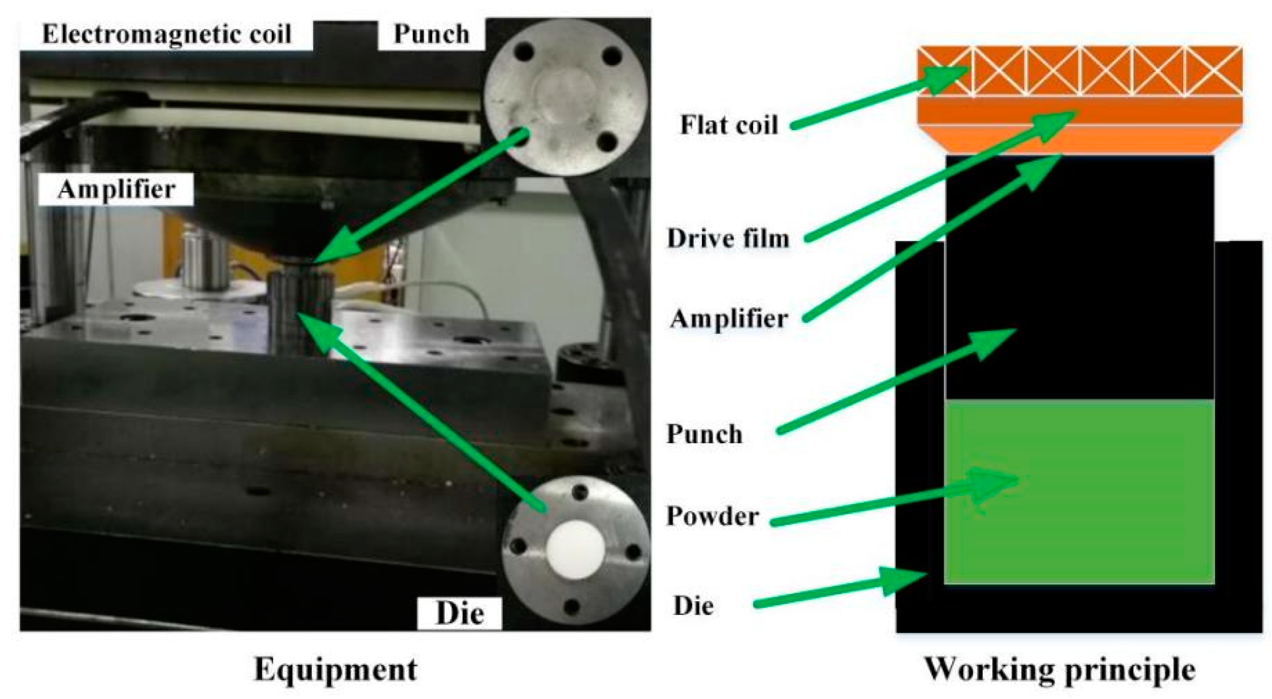
3.1. Experimental Equipment
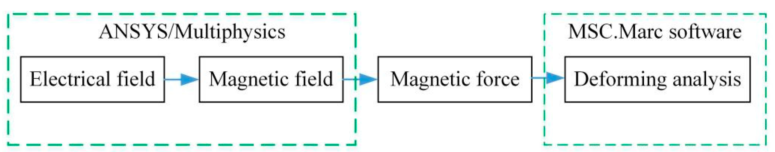
3.2. Finite Element Analysis
3.2.1. Electrical and Magnetic Analysis
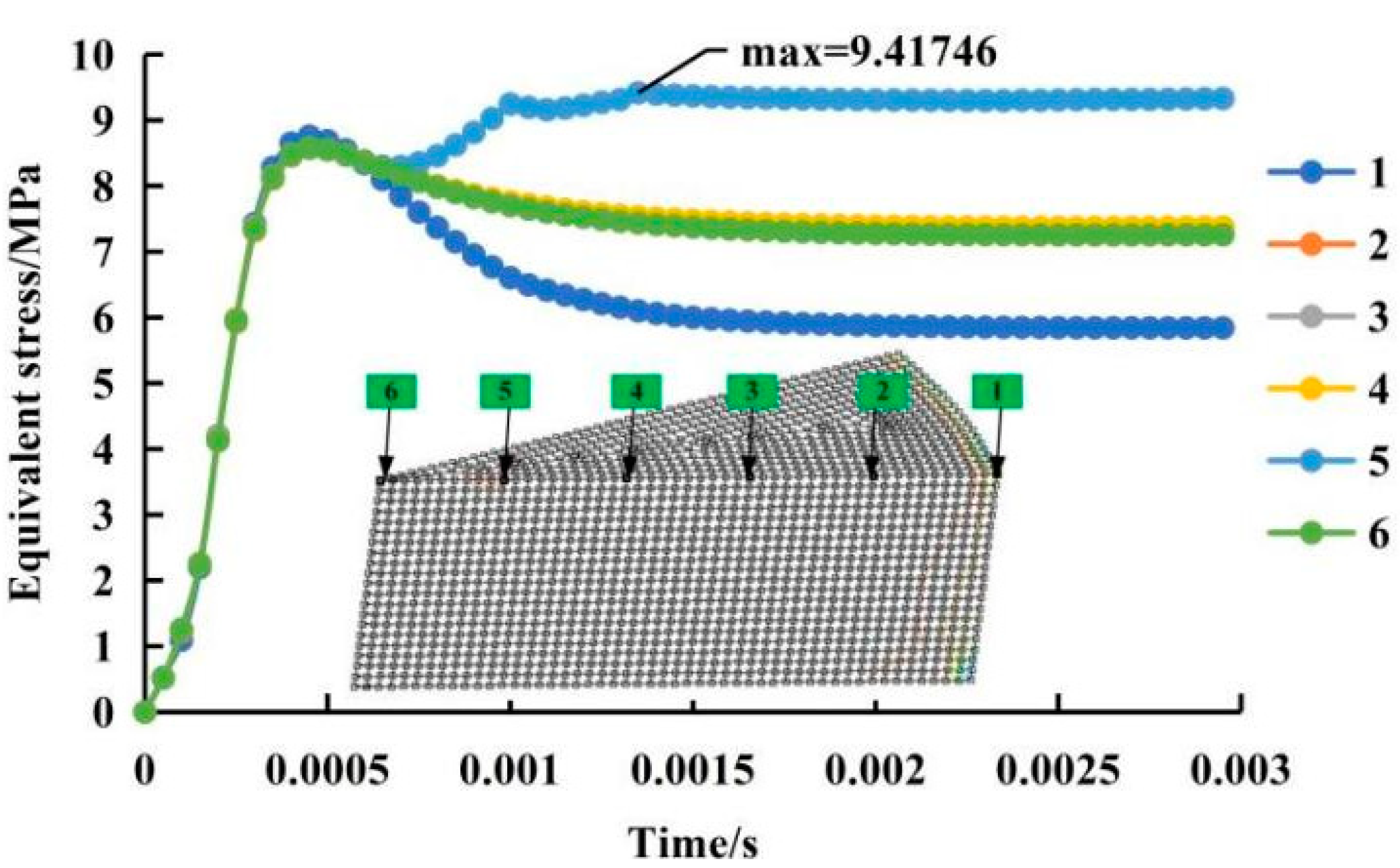
3.2.2. Moulding Analysis
4. Conclusions
Abbreviation
| No | Original Words | Abbreviation |
| 1 | Poly (ether-ketone-ketone) | PEKK |
| 2 | Poly (ether-ether-ketone) | PEEK |
| 3 | Spark Plasma Sintering | SPS |
| 4 | Lead Zirconate Titanate | PZT |
| 5 | Magnetic Pulsed Compaction | MPC |
| 6 | Dynamic Magnetic Consolidation | DMC |
| 7 | Direct Current | DC |
| 8 | Differential Scanning Calorimetry | DSC |
| 9 | Scanning Electron Microscopy | SEM |
| 10 | Finite Element | FE |
Supplementary Materials
Author Contributions
Funding
Institutional Review Board Statement
Informed Consent Statement
Data Availability Statement
Conflicts of Interest
References
- Sherwani, S.F.K.; Ilyas, R.A.; Sapuan, S.M. Application of polymer composite materials in motorcycles:A Comprehensive review. Biocompos. Synth. Compos. Autom. Appl. 2021, 401–426. [Google Scholar] [CrossRef]
- Zherebtsov, D.; Chukov, D.; Torokhov, V.; Statnik, E. Manufacturing of Single-Polymer Composite Materials Based on Ultra-High Molecular Weight Polyethylene Fibers by Hot Compaction. J. Mat. Eng. Perfor. 2020, 29, 1522–1527. [Google Scholar] [CrossRef]
- Biswal, T.; Badjena, S.K.; Pradhan, D. Synthesis of polymer composite materials and their biomediacal applications. J. Mat. Today Proceed. 2020, 30, 305–315. [Google Scholar] [CrossRef]
- Kumar, J.G.K.; Venkates, R.; Babu, H. Tribological and Mechanical behavior of reinforced polymer composite material for clutch facing in automobile application. IOP Conf. Ser. Mat. Sci. Eng. 2020, 954, 012047. [Google Scholar] [CrossRef]
- Yadav, R.; Tirumli, M.; Wang, X.; Naebe, M.; Kandasubramanian, B. Polymer composite for antistatic application in aerospace. Def. Technol. 2020, 16, 107–118. [Google Scholar] [CrossRef]
- Muhammad, A.; Rahman, M.R.; Baini, R.; Bakri, M.K.B. 8–Applications of sustainable polymer composites in automobile and aerospace industry. Adv. Sustain. Polym. Comp. 2021, 185–207. [Google Scholar] [CrossRef]
- Faris, M.A.-Q.; Sapuan, S.M. Natural fiber reinforced polymer composites in industrial applications: Feasibility of date palm fibers for sustainabl. e automotive industry. J. Clean. Prod. 2014, 66, 347–354. [Google Scholar]
- Davies, P.; Cantwell, W.; Kausch, H.H. Measurement of Initiation Values of GIC in IM6/PEEK Composites. Comp. Sci. Tehnol. 1989, 35, 310–313. [Google Scholar] [CrossRef]
- Cortes, L.Q.; Lonjon, A.; Dantras, E.; Lacabanne, C. High-performance thermoplastic composites poly(ether ketone ketone)/silver nanowires: Morphological, mechanical and electrical properties. J. Non-Cryst. Solids 2014, 391, 106–111. [Google Scholar] [CrossRef]
- Stankovich, S.; Dikin, A.D.; Dommetti, G.H.B.; Kohlhaas, K.M.; Zimney, E.J.; Stach, E.A.; Piner, R.D.; Nguyen, S.T.; Ruoff, R.S. Graphene-based composite materials. Nature 2006, 442, 282–286. [Google Scholar] [CrossRef]
- Rivière, L.; Lonjon, A.; Dantras, E.; Lacabanne, C.; Olivier, P.; Gleizes, N.R. Silver fillers aspect ratio influence on electrical and thermal conductivity in PEEK/Ag nanocomposites. Eur. Polym. J. 2016, 85, 115–125. [Google Scholar] [CrossRef]
- Dhand, V.; Rhee, K.Y.; Kim, H.J.; Jung, D.H. A comprehensive review of graphene nanocomposites: Research status and trends. J. Nanomater. 2013, 14, 1–50. [Google Scholar] [CrossRef]
- Lee, C.; Wei, X.; Kysar, J.W.; Hone, J. Measurement of elastic properties and intrinsic strength of monolayer graphene. Science 2008, 321, 385–388. [Google Scholar] [CrossRef]
- Kuilla, T.; Bhadra, S.; Yao, D.; Kim, N.; Bose, H.S.; Lee, J.H. Recent Advances in Graphene Based Polymer Composites. Progr. Polym. Sci. 2010, 35, 1350–1375. [Google Scholar] [CrossRef]
- Ahmed, E.M. Hydrogel: Preparation, characterization, and applications: A review. J. Adv. Res. 2015, 6, 105–121. [Google Scholar] [CrossRef]
- Kim, H.; Miura, Y.; Macosko, C.W. Graphene/polyurethane nanocomposites for improved gas barrier and electrical conductivity. Chem. Mat. 2010, 22, 3441–3450. [Google Scholar] [CrossRef]
- Li, F.; Long, L.; Weng, Y. A Review on the Contemporary Development of Composite Materials Comprising Graphene/Graphene Derivatives. Adv. Mat. Sci. Eng. 2020, 2, 1–16. [Google Scholar] [CrossRef]
- Tiwari, I.; Singh, K.P.; Singh, M. An insight review on the application of polymer-carbon nanotube based composite material in sensor technology. Rus. J. Gen. Chem. 2009, 79, 2685–2694. [Google Scholar] [CrossRef]
- Yang, L.; Zhang, S.; Chen, Z.; Guo, Y.; Luan, J.; Geng, Z.; Wang, G. Design and preparation of graphene/poly (ether ether ketone) composites with excellent electrical conductivity. J. Mat. Sci. 2014, 49, 2372–2382. [Google Scholar] [CrossRef]
- Bessaguet, C.; Dantras, E.; Michon, G.; Chevalier, M.; Laffont, L.; Lacabanne, C. Electrical behavior of a Graphene/PEKK and carbon black/PEKK nanocomposites in the vicinity of the percolation threshold. J. Non-Cryst. Solids 2019, 512, 1–6. [Google Scholar] [CrossRef]
- Dey, B.; Ahad, M.W.; Mezeni, A.A.L.; Sarkhel, G.; Bag, D.S.; Choudhury, A. Enhancing electrical, mechanical, and thermal properties of polybenzimidazole by 3D carbon nanotube@graphene oxide hybrid. Compos. Commun. 2020, 17, 87–96. [Google Scholar] [CrossRef]
- Tkalya, E.; Ghislandi, M.; Otten, R.; Lotya, M.; Alekseev, A.; Van Der Schoot, P.; Koning, C. Experimental and theoretical study of the influence of the state of dispersion of graphene on the percolation threshold of conductive graphene/polystyrene nanocomposites. ACS Appl. Mat. Interf. 2014, 6, 15113–15121. [Google Scholar] [CrossRef] [PubMed]
- Asprone, D.; Auricchio, F.; Menna, C.; Mercuri, V. 3D printing of reinforced concrete elements: Technology and design approach. Constr. Build. Mat. 2018, 165, 218–231. [Google Scholar] [CrossRef]
- Ngo, T.D.; Kashani, A.; Immbalzano, G.; Nguyen Kate, T.Q.; Hui, D. Additive manufacturing (3D printing): A review of materials, methods, applications and challenges. Compos. Part B Eng. 2018, 143, 172–196. [Google Scholar] [CrossRef]
- Calignano, F.; Manfredi, D.; Ambrosio, E.P.; Biamino, S.; Lombardi, M.; Atzeni, E.; Salmi, A.; Minetola, P.; Fino, P. Overview on additive manufacturing technologies. Proceed. IEEE 2017, 105, 593–612. [Google Scholar] [CrossRef]
- Wang, Y.; Zhou, Y.; Lin, L.; Corker, J.; Fan, M. Overview of 3D additive manufacturing (AM) and corresponding AM composites. Compos. Part A 2020, 139, 106114. [Google Scholar] [CrossRef]
- Utela, B.; Storti, D.; Anderson, R.; Ganter, M. A review of process development steps for new material systems in three dimensional printing (3DP). J. Manuf. Proc. 2008, 10, 96–104. [Google Scholar] [CrossRef]
- Butschher, A.; Bohner, M.; Roth, C.; Ernstberger, A.; Heuberger, R.; Doebelin, N.; Von Rohr, P.R.; Müller, R. Printability of calcium phosphate powders for three-dimensional printing of tissue engineering scaffolds. Acta Biomater. 2012, 8, 373–385. [Google Scholar] [CrossRef]
- Huang, Z.; Tang, Y.; Guo, H.; Feng, X.; Zhang, T.; Li, P.; Qian, B.; Xie, Y. 3D printing of ceramics and graphene circuits-on-ceramics by thermal bubble inkjet technology and high temperature sintering. Ceram. Int. 2020, 46, 10096–10104. [Google Scholar] [CrossRef]
- Bikas, H.; Stavropoulos, P.; Chryssolouris, G. Additive manufacturing methods and modelling approaches: A critical review. Int. J. Adv. Manuf. Technol. 2016, 83, 389–405. [Google Scholar] [CrossRef]
- Boparai, K.S.; Singh, R.; Fabbrocino, F.; Fraternali, F. Thermal characterization of recycled polymer for additive manufacturing applications. Compos. Part B Eng. 2016, 106, 42–47. [Google Scholar] [CrossRef]
- Rahman, A.; Singh, A.; Harimkar, S.P.; Singh, R.P. Spark Plasma Sintering and Characterization of Graphene Reinforced Silicon Carbide Nanocomposites. Compos. Mat. Join. Technol. Compos. 2013, 7, 139–146. [Google Scholar]
- Meng, Z.H.; Huang, S.Y.; Yang, M. Effects of processing parameters on density and electric properties of electric ceramic compacted by low-voltage electromagnetic compaction. J. Mat. Proces. Technol. 2009, 209, 672–678. [Google Scholar] [CrossRef]
- Hong, S.J.; Lee, G.H.; Rhee, C.K.; Kim, W.W.; Lee, K.S. Magnetic pulsed compaction of ferromagnetic nano-powders for soft-magnetic core. Mat. Sci. Eng. A 2007, 449, 401–406. [Google Scholar] [CrossRef]
- Chelluri, B. Dynamic Magnetic Consolidation (DMC) Process for Powder Consolidation of Advanced Materials. Mat. Manuf. Proces. 2007, 1127–1142. [Google Scholar] [CrossRef]
- Song, J.W.; Raihanuzzaman, R.M.; Hong, S.J. Consolidation of WC-Co alloys by magnetic pulsed compaction and evaluation of their mechanical properties. Powder Technol. 2013, 235, 723–727. [Google Scholar] [CrossRef]
- Chae, H.J.; Kim, Y.D.; Kim, T.S. Microstructure and mechanical properties of rapidly solidified Mg alloy powders compacted by magnetic pulsed compaction method. J. Alloys Compd. 2011, 5095, S250–S253. [Google Scholar] [CrossRef]
- Boltachev, G.S.; Volkov, N.B.; Chingina, E.A. Nanopowders in dynamic magnetic pulse compaction processes. Nanotechnol. Rus. 2014, 9, 650–659. [Google Scholar] [CrossRef]
- Dobrov, S.V.; Ivanov, V.V. Simulation of pulsed magnetic molding of long powdered products. Tech. Phys. 2004, 49, 413–419. [Google Scholar] [CrossRef]
- Boltachev, G.S.; Volkon, N.B.; Dobrov, S.V.; Ivanov, V.V.; Nozdrin, A.A.; Paranin, S.N. Simulation of radial pulsed magnetic compaction of a granulated medium in a quasi-static approximation. Tech. Phys. 2007, 52, 1306–1315. [Google Scholar] [CrossRef]
- Ovlevsky, E.A.; Bokov, A.A.; Boltachev, G.S.; Volkon, N.B.; Zayats, S.V.; Ilyina, A.M.; Nozdrin, A.A.; Paranin, S.N. Modeling and optimization of uniaxial magnetic pulse compaction of nanopowders. Acta Mech. 2013, 224, 3177–3195. [Google Scholar] [CrossRef]
- Mamalis, A.G.; Manolakos, D.E.; Kladas, A.G.; Koumoutsos, A.K. Electromagnetic forming tools and processing conditions: Numerical simulation. Mat. Manuf. Proc. 2007, 21, 411–423. [Google Scholar] [CrossRef]
- Huang, H.; Kelder, E.M.; Jak, M.J.G.; Schoonman, J. Influences of dynamic compaction on lithium intercalation into graphite anode. Solid State Ionics 2001, 139, 67–74. [Google Scholar] [CrossRef]
- Xu, F.; Zhang, H.; Zhao, S.; Chen, C.; Cao, M.; Chen, W. Optimized Calibration Procedure of the Damage Parameters of AA6082-T6 Sheets. Materials 2018, 11, 248. [Google Scholar] [CrossRef] [PubMed]
- Mironovs, V.; Korjakins, A.; Tatarinov, A.; Barone, E.; Glushchenkov, V. Combined static-dynamic compaction of metal powder and ceramic materials. Mat. Sci. Eng. 2017, 251, 012020. [Google Scholar] [CrossRef]
- Li, C.F. Electromagnetic Forming. Sci. Press 2016, 252–287. [Google Scholar]


| No | Pressure (A) | Pre-Pressure Time (B) | Heating Rate (C) | Cooling Rate (D) | Holding Time (E) |
|---|---|---|---|---|---|
| 1 | 6 MPa | 1 min | 40 °C/min | 5 °C/min | 1 min |
| 2 | 8 MPa | 3 min | 45 °C/min | 10 °C/min | 3 min |
| 3 | 10 MPa | 5 min | 50 °C/min | 15 °C/min | 5 min |
| 4 | 12 MPa | 7 min | 55 °C/min | 20 °C/min | 7 min |
| 5 | 14 MPa | 9 min | 60 °C/min | 25 °C/min | 9 min |
| Tools | Pressure | Pre-Pressure | Heating Rate | Cooling Rate | Holding Time | Sintering Temperature | Circulating Water |
|---|---|---|---|---|---|---|---|
| Graphite | 10 MPa | 5 min | 50 °C/min | 15 °C/min | 5 min | 145 °C | 30 °C |
| Voltage (KV) | Capacitance (μF) (Adjustable) |
|---|---|
| 0.45, 1, 2, 3, 5, 10, 20, 30, 50, 100, 200 | 500–10,000 μF |
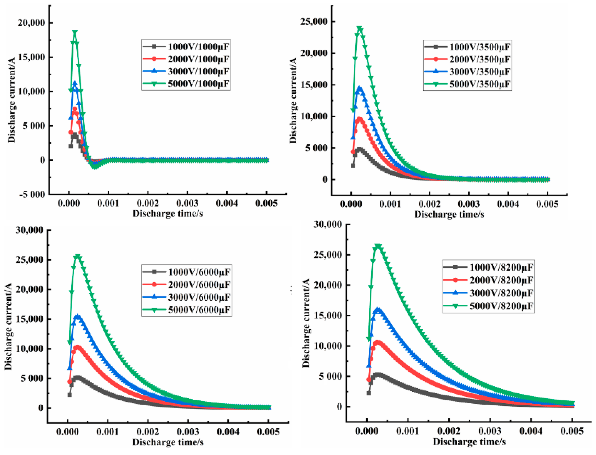
| No | Voltage (V) | Capacitance (µF) | Energy (KJ) | Inductance (µH) | Resistance (Ω) | Densification (Max) | Electromagnetic Force (N) | Discharge Current (A) |
|---|---|---|---|---|---|---|---|---|
| 1 | 1000 | 1000 | 0.5 | 0.164 | 13.795 | 0.4286 | −32,020 | 3732.2 |
| 2 | 1000 | 3500 | 1.75 | 0.164 | 13.795 | 0.4796 | −52,480 | 4805.96 |
| 3 | 1000 | 6000 | 3 | 0.164 | 13.795 | 0.5147 | −59,500 | 5148.8 |
| 4 | 1000 | 8200 | 4.1 | 0.164 | 13.795 | 0.5774 | −63,340 | 5309.63 |
| 5 | 2000 | 1000 | 2 | 0.164 | 13.795 | 0.4808 | −128,100 | 7464.4 |
| 6 | 2000 | 3500 | 7 | 0.164 | 13.795 | 0.5911 | −209,900 | 9611.92 |
| 7 | 2000 | 6000 | 12 | 0.164 | 13.795 | 0.6578 | −238,000 | 10,297.6 |
| 8 | 2000 | 8200 | 16.4 | 0.164 | 13.795 | 0.7614 | −253,300 | 10,619.3 |
| 9 | 3000 | 1000 | 4.5 | 0.164 | 13.795 | 0.5383 | −288,200 | 11,196.6 |
| 10 | 3000 | 3500 | 15.75 | 0.164 | 13.795 | 0.6962 | −472,300 | 14,417.9 |
| 11 | 3000 | 6000 | 27 | 0.164 | 13.795 | 0.7786 | −535,500 | 15,446.4 |
| 12 | 3000 | 8200 | 36.9 | 0.164 | 13.795 | 0.961 | −570,000 | 15,928.9 |
| 13 | 5000 | 1000 | 12.5 | 0.164 | 13.795 | 0.7631 | −800,600 | 18,661 |
| 14 | 5000 | 3500 | 43.75 | 0.164 | 13.795 | 0.9444 | −1,312,000 | 24,029.8 |
| 15 | 5000 | 6000 | 75 | 0.164 | 13.795 | 0.9691 | −1,488,000 | 25,744 |
| 16 | 5000 | 8200 | 102.5 | 0.164 | 13.795 | 0.9895 | −1,583,000 | 26,548.1 |
Publisher’s Note: MDPI stays neutral with regard to jurisdictional claims in published maps and institutional affiliations. |
© 2021 by the authors. Licensee MDPI, Basel, Switzerland. This article is an open access article distributed under the terms and conditions of the Creative Commons Attribution (CC BY) license (http://creativecommons.org/licenses/by/4.0/).
Share and Cite
Wang, Q.; Jia, D.; Pei, X.; Wu, X.; Xu, F.; Wang, H.; Cao, M.; Chen, H. Investigation of Electromagnetic Pulse Compaction on Conducting Graphene/PEKK Composite Powder. Materials 2021, 14, 636. https://doi.org/10.3390/ma14030636
Wang Q, Jia D, Pei X, Wu X, Xu F, Wang H, Cao M, Chen H. Investigation of Electromagnetic Pulse Compaction on Conducting Graphene/PEKK Composite Powder. Materials. 2021; 14(3):636. https://doi.org/10.3390/ma14030636
Chicago/Turabian StyleWang, Quanbin, Deli Jia, Xiaohan Pei, Xuelian Wu, Fan Xu, Huixiong Wang, Minghao Cao, and Haidong Chen. 2021. "Investigation of Electromagnetic Pulse Compaction on Conducting Graphene/PEKK Composite Powder" Materials 14, no. 3: 636. https://doi.org/10.3390/ma14030636
APA StyleWang, Q., Jia, D., Pei, X., Wu, X., Xu, F., Wang, H., Cao, M., & Chen, H. (2021). Investigation of Electromagnetic Pulse Compaction on Conducting Graphene/PEKK Composite Powder. Materials, 14(3), 636. https://doi.org/10.3390/ma14030636