
A Design Method to Induce Ductile Failure of Flexural Strengthened One-Way RC Slabs


Abstract
:1. Introduction
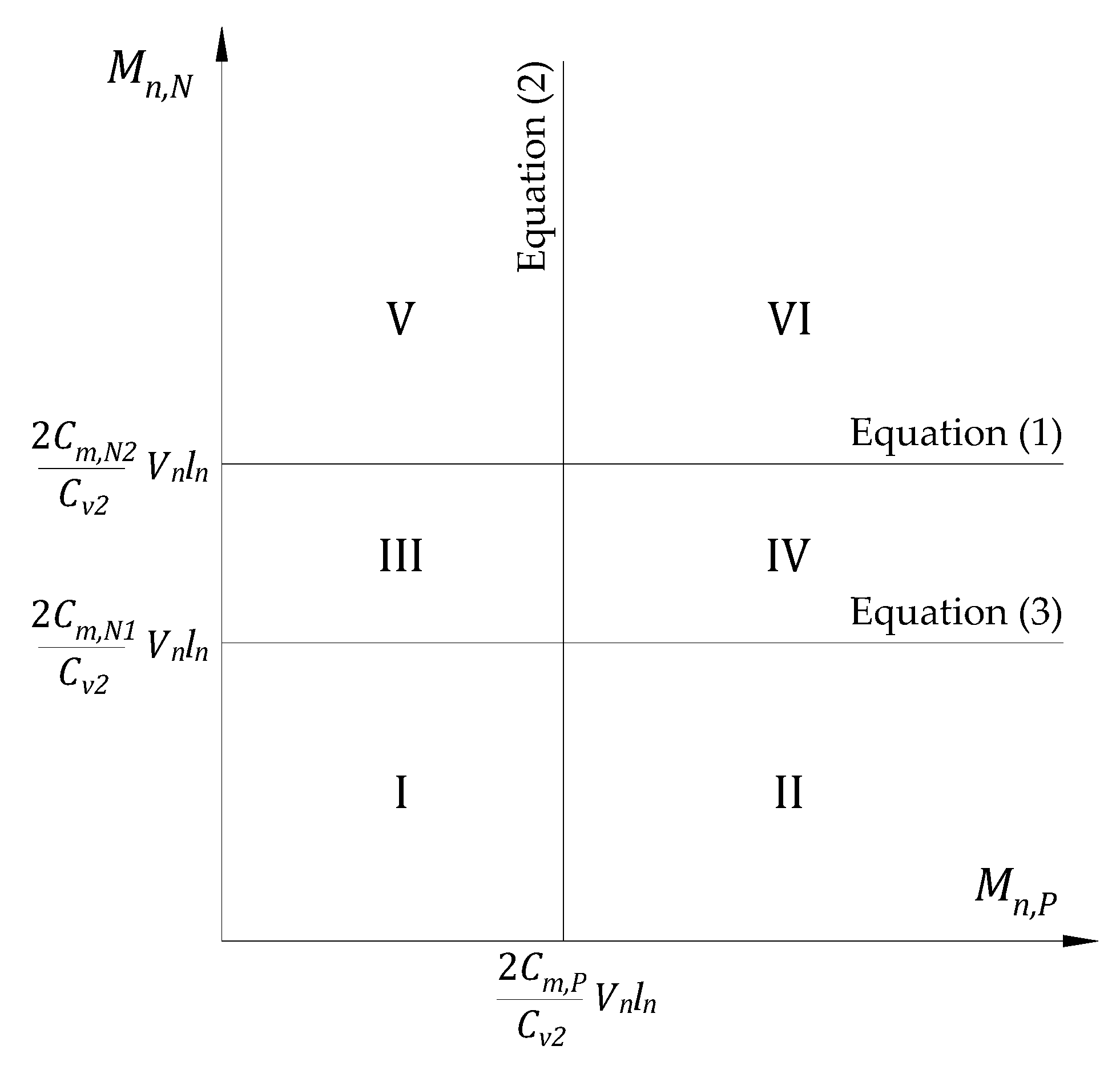
2. Failure Limits
- Failure mode D-1
- Failure mode D-2
- Failure mode D-3
3. Design Example
4. Results and Discussions
5. Conclusions
Author Contributions
Funding
Institutional Review Board Statement
Informed Consent Statement
Data Availability Statement
Conflicts of Interest
Appendix A


References
- Zamani Beydokhti, E.; Shariatmadar, H. Strengthening and rehabilitation of exterior RC beam–column joints using carbon-FRP jacketing. Mater. Struct. 2016, 49, 5067–5083. [Google Scholar] [CrossRef]
- Martínez, S.; de Diego, A.; Castro, V.J.; Echevarría, L.; Barroso, F.J.; Rentero, G.; Soldado, R.P.; Gutiérrez, J.P. Strengthening of low-strength concrete columns with fibre reinforced polymers. Full-scale tests. Infrastructures 2020, 5, 91. [Google Scholar] [CrossRef]
- Hariri-Ardebili, M.A.; Sanchez, L.; Rezakhani, R. Aging of concrete structures and infrastructures: Causes, consequences, and cures. Adv. Mater. Sci. Eng. 2020, 2020, 9370591. [Google Scholar] [CrossRef]
- Fanning, P.J.; Kelly, O. Ultimate response of rc beams strengthened with CFRP plates. J. Compos. Constr. 2001, 5, 122–127. [Google Scholar] [CrossRef]
- Ma, Y.; Zhang, J.; Wang, L.; Liu, Y. Probabilistic prediction with Bayesian updating for strength degradation of RC bridge beams. Struct. Saf. 2013, 44, 102–109. [Google Scholar] [CrossRef]
- Fathelbab, F.A.; Ramadan, M.S.; Al-Tantawy, A. Strengthening of RC bridge slabs using CFRP sheets. Alex. Eng. J. 2014, 53, 843–854. [Google Scholar] [CrossRef] [Green Version]
- Moon, J.; Taha, M.M.R.; Kim, J.J. Flexural strengthening of RC slabs using a hybrid FRP-UHPC system including shear connector. Adv. Mater. Sci. Eng. 2017, 2017, 4387545. [Google Scholar] [CrossRef] [Green Version]
- Bashandy, A. Flexural strengthening of reinforced concrete beams using valid strengthening techniques. Arch. Civ. Eng. 2013, 59, 275–293. [Google Scholar] [CrossRef] [Green Version]
- Canning, L.; Luke, S. Development of FRP bridges in the UK—An overview. Adv. Struct. Eng. 2010, 13, 823–835. [Google Scholar] [CrossRef]
- Haji, M.; Naderpour, H.; Kheyroddin, A. Experimental study on influence of proposed FRP-strengthening techniques on RC circular short columns considering different types of damage index. Compos. Struct. 2019, 209, 112–128. [Google Scholar] [CrossRef]
- Barris, C.; Sala, P.; Gómez, J.; Torres, L. Flexural behaviour of FRP reinforced concrete beams strengthened with NSM CFRP strips. Compos. Struct. 2020, 241, 112059. [Google Scholar] [CrossRef]
- Mukhtar, F.M.; Arowojolu, O. Recent developments in experimental and computational studies of hygrothermal effects on the bond between FRP and concrete. J. Reinf. Plast. Compos. 2020, 39, 422–442. [Google Scholar] [CrossRef]
- Basaran, B.; Kalkan, I. Development length and bond strength equations for FRP bars embedded in concrete. Compos. Struct. 2020, 251, 112662. [Google Scholar] [CrossRef]
- Emmons, P.H.; Vaysburd, A.M.; Thomas, J. Strengthening concrete structures, Part II. Concr. Int. 1998, 20, 56–60. [Google Scholar]
- Rizkalla, S.; Hassan, T.; Hassan, N. Design recommendations for the use of FRP for reinforcement and strengthening of concrete structures. Prog. Struct. Eng. Mater. 2003, 5, 16–28. [Google Scholar] [CrossRef]
- De Lorenzis, L.; Teng, J.G. Near-surface mounted FRP reinforcement: An emerging technique for strengthening structures. Compos. Part B Eng. 2007, 38, 119–143. [Google Scholar] [CrossRef]
- El Maaddawy, T.; Soudki, K. Strengthening of reinforced concrete slabs with mechanically-anchored unbonded FRP system. Constr. Build. Mater. 2008, 22, 444–455. [Google Scholar] [CrossRef]
- Mugahed Amran, Y.H.; Alyousef, R.; Rashid, R.S.M.; Alabduljabbar, H.; Hung, C.-C. Properties and applications of FRP in strengthening RC structures: A review. Structures 2018, 16, 208–238. [Google Scholar] [CrossRef]
- Mosallam, A.; Taha, M.M.R.; Kim, J.J.; Nasr, A. Strength and ductility of RC slabs strengthened with hybrid high-performance composite retrofit system. Eng. Struct. 2012, 36, 70–80. [Google Scholar] [CrossRef]
- Salman, W.D.; Mansor, A.A.; Mahmood, M. Behavior of reinforced concrete one-way slabs strengthened by CFRP sheets in flexural zone. Int. J. Civ. Eng. Technol. 2018, 9, 10. [Google Scholar]
- Torabian, A.; Isufi, B.; Mostofinejad, D.; Pinho Ramos, A. Flexural strengthening of flat slabs with FRP composites using EBR and EBROG methods. Eng. Struct. 2020, 211, 110483. [Google Scholar] [CrossRef]
- Moshiri, N.; Czaderski, C.; Mostofinejad, D.; Hosseini, A.; Sanginabadi, K.; Breveglieri, M.; Motavalli, M. Flexural strengthening of RC slabs with nonprestressed and prestressed CFRP strips using EBROG method. Compos. Part B Eng. 2020, 201, 108359. [Google Scholar] [CrossRef]
- Rabinovitch, O.; Frostig, Y. Experiments and analytical comparison of RC beams strengthened with CFRP composites. Compos. Part B Eng. 2003, 34, 663–677. [Google Scholar] [CrossRef]
- Hawileh, R.A.; Rasheed, H.A.; Abdalla, J.A.; Al-Tamimi, A.K. Behavior of reinforced concrete beams strengthened with externallybonded hybrid fiber reinforced polymer systems. Mater. Des. 2014, 53, 972–982. [Google Scholar] [CrossRef] [Green Version]
- Haciyev, V.C.; Sofiyev, A.H.; Kuruoglu, N. Free bending vibration analysis of thin bidirectionally exponentially graded orthotropic rectangular plates resting on two-parameter elastic foundations. Compos. Struct. 2018, 184, 372–377. [Google Scholar] [CrossRef]
- Breveglieri, M.; Barros, J.; Dalfre, G.; Aprile, A. Assessment of the effectiveness of a NSM-CFRP flexural strengthening technique for continuous RC slabs. In Proceedings of the Fib Symposium PRAGUE 2011, Session 5: Combination of Structural Concrete with Other Materials, Prague, Czech Republic, 8–10 June 2011; pp. 1–10. [Google Scholar]
- Al-Rousan, R.; Issa, M.; Shabila, H. Performance of reinforced concrete slabs strengthened with different types and configurations of CFRP. Compos. Part B Eng. 2012, 43, 510–521. [Google Scholar] [CrossRef]
- Phan Duy, N.; Viet Quoc, D. Limiting reinforcement ratios for hybrid GFRP/Steel reinforced concrete beams. Int. J. Eng. Technol. Innov. 2021, 11, 1–11. [Google Scholar] [CrossRef]
- Sherwood, E.; Bentz, E. Where is shear reinforcement required? Review of research results and design procedures. Aci Struct. J. 2008, 108, 590–600. [Google Scholar]
- Zhou, C.; Wang, B.; Ma, J.; You, Z. Dynamic axial crushing of origami crash boxes. Int. J. Mech. Sci. 2016, 118, 1–12. [Google Scholar] [CrossRef]
- Zhou, C.; Zhou, Y.; Wang, B. Crashworthiness design for trapezoid origami crash boxes. Thin Walled Struct. 2017, 117, 257–267. [Google Scholar] [CrossRef]
- Ming, S.; Zhou, C.; Li, T.; Song, Z.; Wang, B. Energy absorption of thin-walled square tubes designed by kirigami approach. Int. J. Mech. Sci. 2019, 157–158, 150–164. [Google Scholar] [CrossRef]
- FIB. Externally Bonded FRP Reinforcement for RC Structures; Bulletin No. 14; FIB: Lausanne, Switzerland, 2001. [Google Scholar]
- Bocciarelli, M.; Feo, C.D.; Nisticò, N.; Pisani, M.A.; Poggi, C. Failure of RC beams strengthened in bending with unconventionally arranged CFRP laminates. Compos. Part B Eng. 2013, 54, 246–254. [Google Scholar] [CrossRef]
- Nair, A.; Cai, C.S.; Kong, X. Using acoustic emission to monitor failure modes in CFRP-strengthened concrete structures. J. Aerosp. Eng. 2020, 33, 04019110. [Google Scholar] [CrossRef]
- Al-Jelawy Haider, M.; Mackie Kevin, R. Durability and failure modes of concrete beams strengthened with polyurethane or epoxy CFRP. J. Compos. Constr. 2021, 25, 04021021. [Google Scholar] [CrossRef]
- Kim, J.J.; Noh, H.-C.; Taha, M.M.R.; Mosallam, A. Design limits for RC slabs strengthened with hybrid FRP–HPC retrofit system. Compos. Part B 2013, 51, 19–27. [Google Scholar] [CrossRef] [Green Version]
- Beer, F.P.; Johnston, E.R.; DeWolf, J.T.; Mazurek, D.F. Mechanics of Materials; McGraw-Hill: New York, NY, USA, 2014. [Google Scholar]
- Institute, A.C. ACI Committee 318. In Building Code Requirements for Structural Concrete (ACI 318-11) and Commentary; American Concrete Institute: Farmington Hills, MI, USA, 2011. [Google Scholar]
- ACI Committee 440. Guide for the design and construction of externally bonded FRP systems for strengthening concrete structures. In ACI 440.2R-08; American Concrete Institute: Farmington Hills, MI, USA, 2008. [Google Scholar]
- ACI Committee 440. Report on Fiber-Reinforced Polymer (FRP) Reinforcement for Concrete Structures. In ACI 440R-07; American Concrete Institute: Farmington Hills, MI, USA, 2007. [Google Scholar]


| Failure Modes | First Plastic Hinge | Second Plastic Hinge | Third Plastic Hinge | Shear Failure | Failure Type |
|---|---|---|---|---|---|
| D-1 | N2 | N1 | M | - | Ductile |
| D-2 | N2 | M | N1 | - | Ductile |
| D-3 | M | N2 | N1 | - | Ductile |
| DB-1 | N2 | N1 | - | N2 | Brittle |
| DB-2 | N2 | M | - | N2 | Brittle |
| DB-3a | M | - | - | N2 | Brittle |
| DB-3b | M | N2 | - | N2 | Brittle |
| B-1 | N2 | - | - | N2 | Brittle |
| B-2 | - | - | - | N2 | Brittle |
| Section | h (mm) | b (mm) | As (mm2) | d (mm) | f’c (MPa) | γc (kg/m3) | fy (MPa) | Es (GPa) |
|---|---|---|---|---|---|---|---|---|
| Supports | 150 | 1000 | 355 | 120 | 27 | 2400 | 410 | 200 |
| Mid-span |
| Calculation | Existing RC Slab |
|---|---|
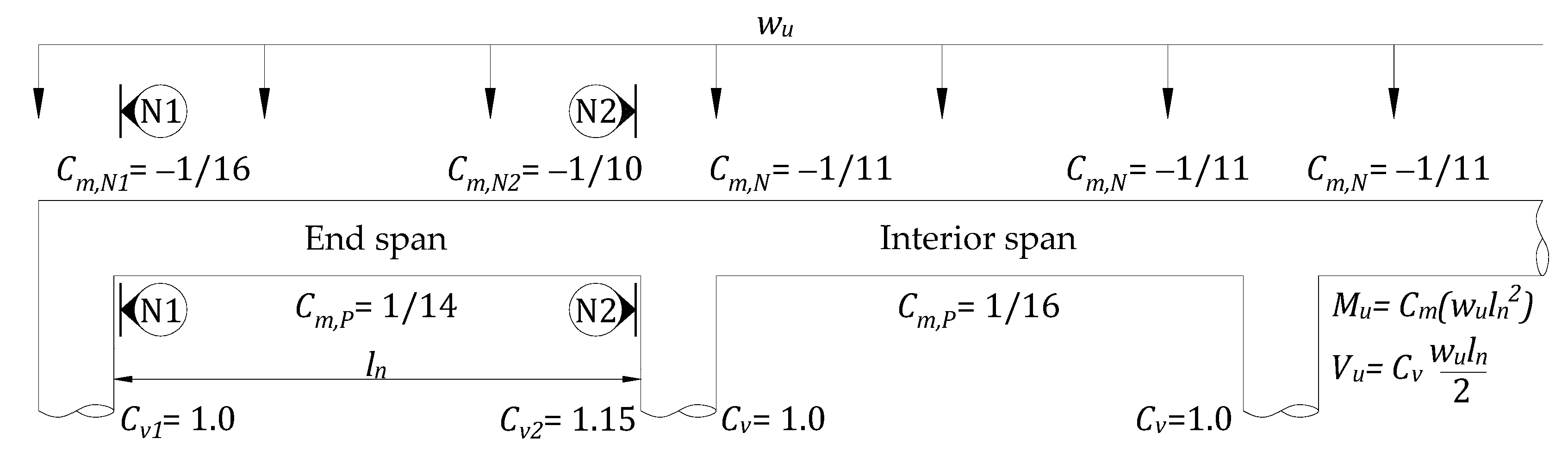
| Moment and shear coefficients for the end span of the column support case [39] | |
| Designed resistance | = 77.94 kNm; |
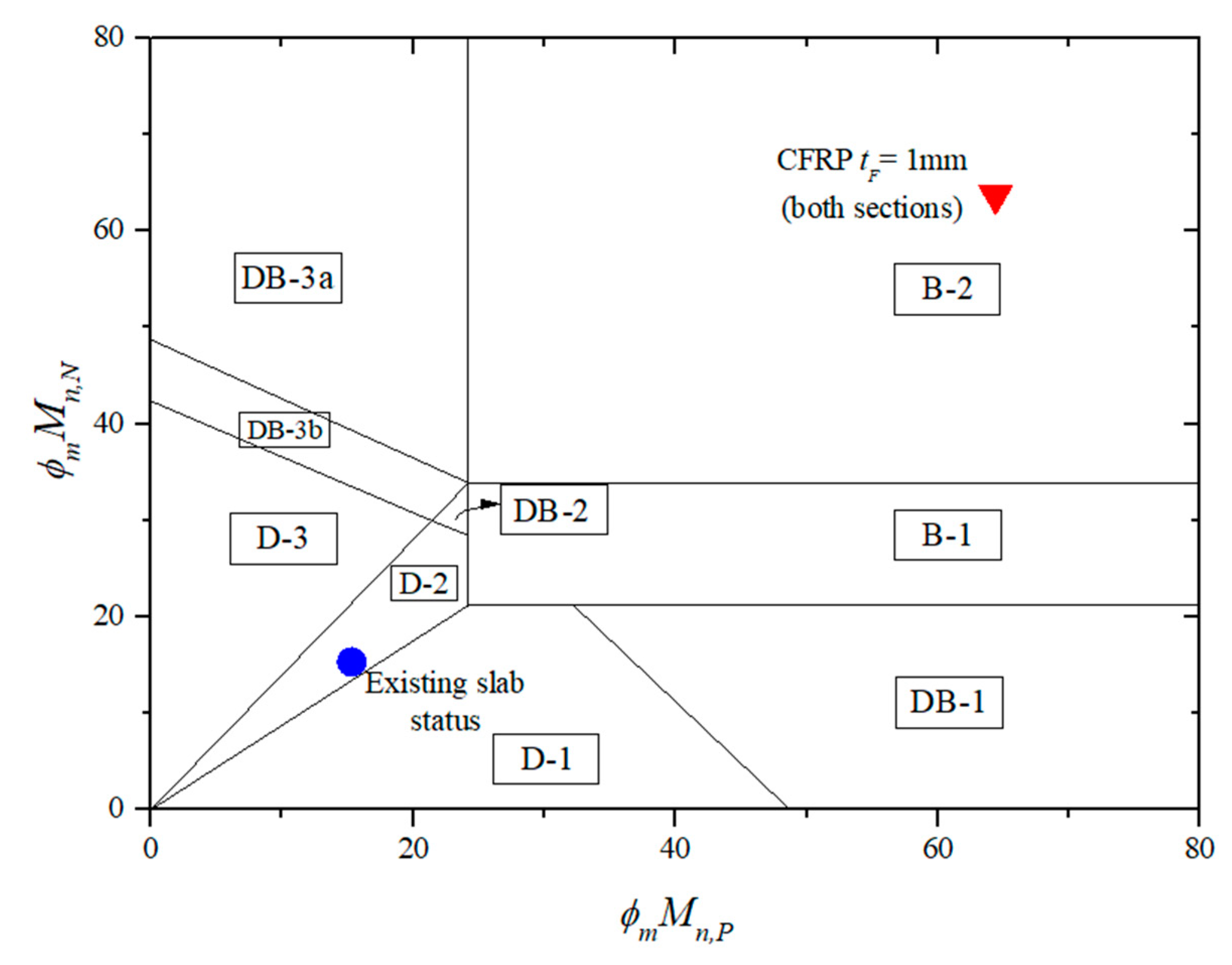
| Failure mode | D-2, as shown in Figure 6 |
| Ultimate failure load: Equation (5) for D-2 | |
| Preparatory computations for strengthened design | |
| Self-weight | |
| Factored moment | At N2 section At mid-span section |
| Modulus of elasticity | |
| Cracking moment Neutral axis depth c = kd | At both sections (N2 and mid-span sections) |
| Procedure | Strengthened Slab |
|---|---|
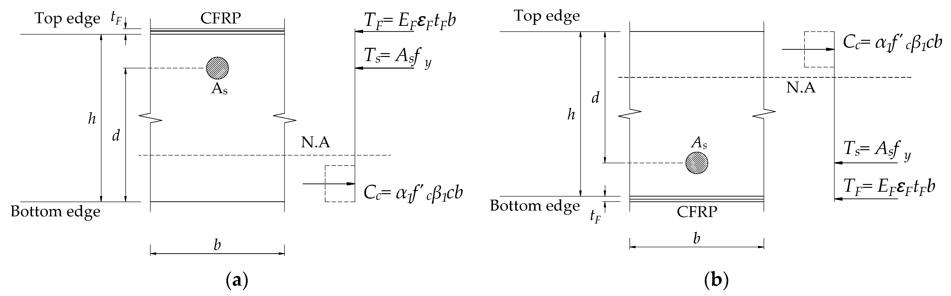
| 1. CFRP thickness, tF | At both sections: tF,N = tF,P = 1 mm |
| 2. Existing state of strain kd is c in Table 3 | At N2 section: At mid-span section: |
| 3. Design strain of CFRP | |
| 4. Assume concrete strain at failure ε Revise ε until equilibrium achieved | At both sections: |
| 5. Compute neutral axis depth | At both sections: |
| 6. Compute CFRP strain | At N2 section: At mid-span section: |
| 7. Compute tension steel strain | At both sections: |
| 8. Check for force equilibrium , is strain relative to Check the neutral axis depth | , At N2 section: (OK) At mid-span section: (OK) Assumption of ε is satisfied. |
| 9. Compute flexural strength at N2 section provided by - Steel: - CFRP: | |
| 10. Compute flexural strength at mid-span section provided by - Steel: - CFRP: | |
| 11. The design flexural strength | At N2 section: At mid-span section: |
| 12. The design shear strength | |
| 13. Failure mode | B-2, as shown in Figure 6 |
| 14. Ultimate failure load Equation (7) for B-2 |
| Slabs | Failure Mode | tFN (mm) | tFP (mm) | ||
|---|---|---|---|---|---|
| Existing slab | D-2 | 31.0 | [100%] | - | - |
| Strengthened both sections | D-2 | 47.9 | [155%] | 0.12 | 0.12 |
| Strengthened negative sections | D-3 | 47.1 | [152%] | 0.26 | - |
Publisher’s Note: MDPI stays neutral with regard to jurisdictional claims in published maps and institutional affiliations. |
© 2021 by the authors. Licensee MDPI, Basel, Switzerland. This article is an open access article distributed under the terms and conditions of the Creative Commons Attribution (CC BY) license (https://creativecommons.org/licenses/by/4.0/).
Share and Cite
Nguyen, H.Q.; Nguyen, T.N.M.; Lee, D.H.; Kim, J.J. A Design Method to Induce Ductile Failure of Flexural Strengthened One-Way RC Slabs. Materials 2021, 14, 7647. https://doi.org/10.3390/ma14247647
Nguyen HQ, Nguyen TNM, Lee DH, Kim JJ. A Design Method to Induce Ductile Failure of Flexural Strengthened One-Way RC Slabs. Materials. 2021; 14(24):7647. https://doi.org/10.3390/ma14247647
Chicago/Turabian StyleNguyen, Huy Q., Tri N. M. Nguyen, Do Hyung Lee, and Jung J. Kim. 2021. "A Design Method to Induce Ductile Failure of Flexural Strengthened One-Way RC Slabs" Materials 14, no. 24: 7647. https://doi.org/10.3390/ma14247647
APA StyleNguyen, H. Q., Nguyen, T. N. M., Lee, D. H., & Kim, J. J. (2021). A Design Method to Induce Ductile Failure of Flexural Strengthened One-Way RC Slabs. Materials, 14(24), 7647. https://doi.org/10.3390/ma14247647