
Cyclic Relaxation, Impact Properties and Fracture Toughness of Carbon and Glass Fiber Reinforced Composite Laminates


Abstract
:1. Introduction
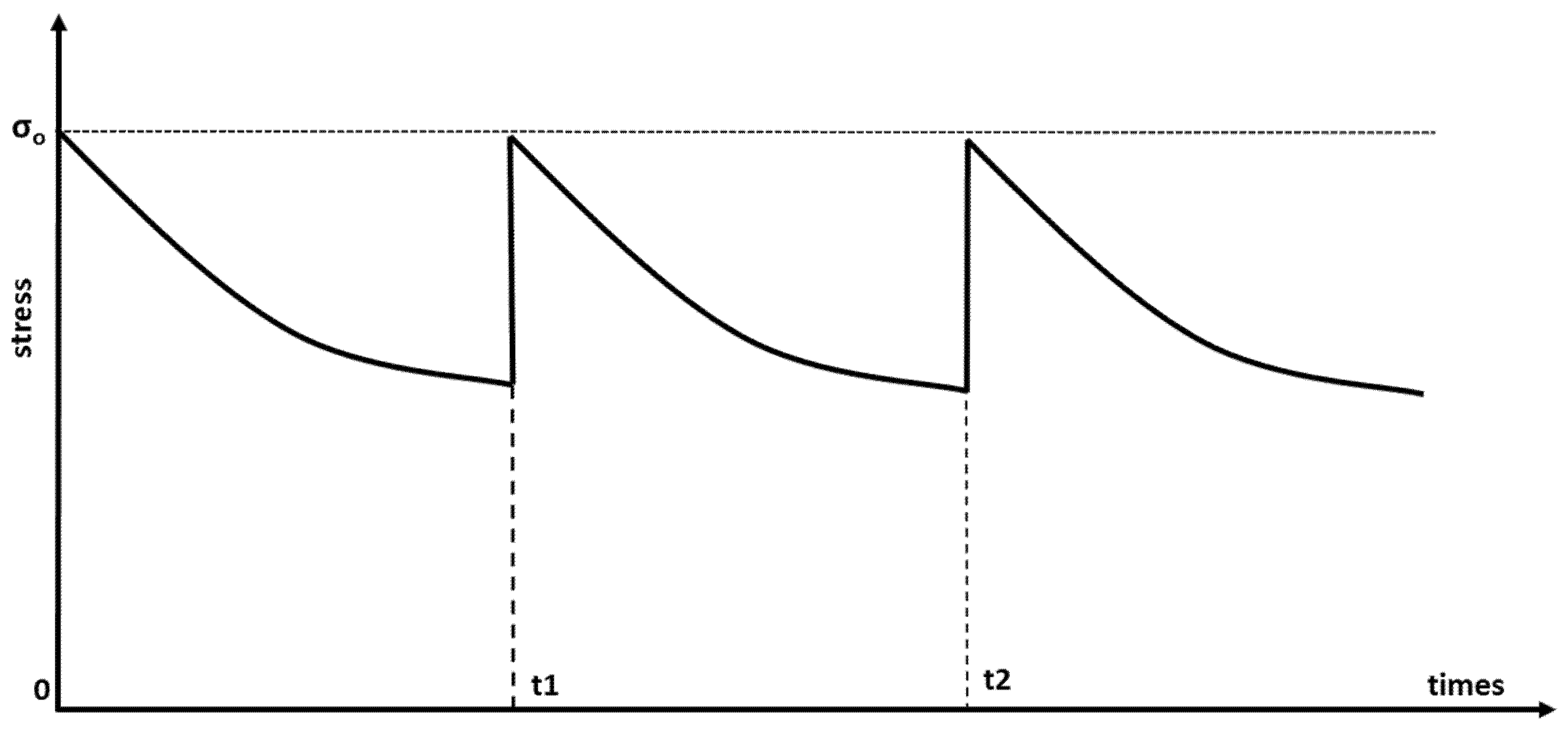
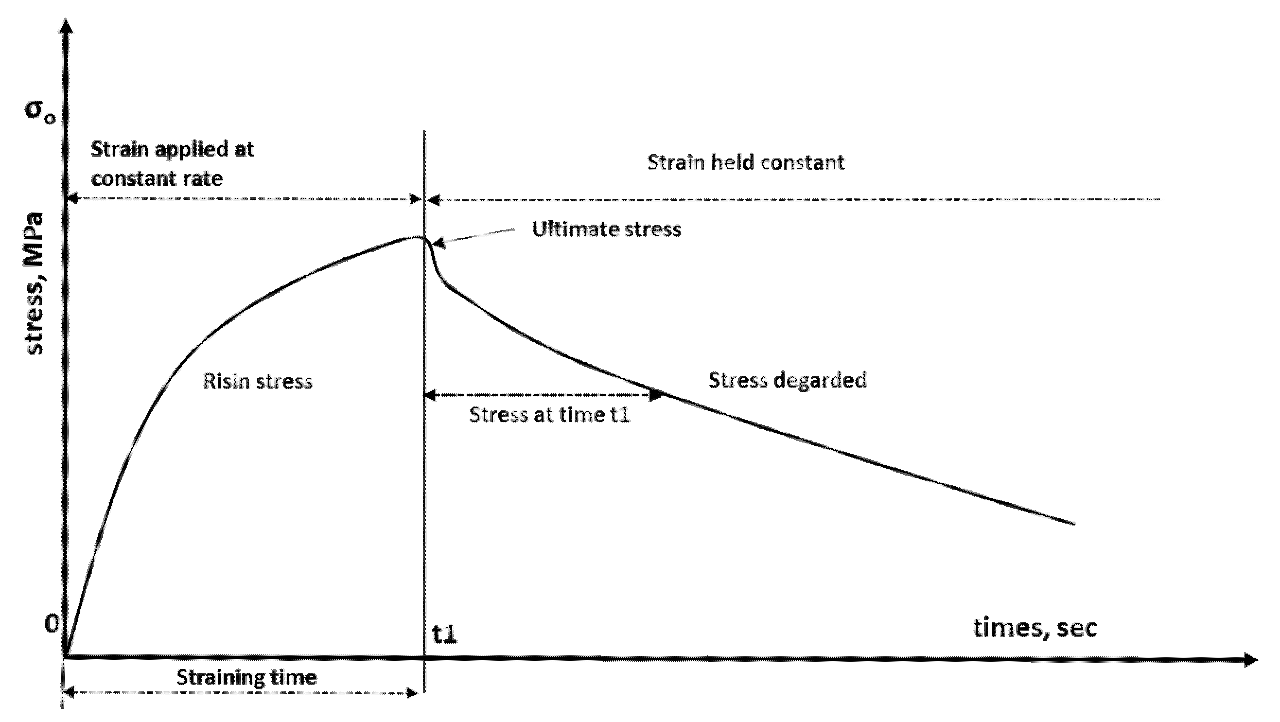
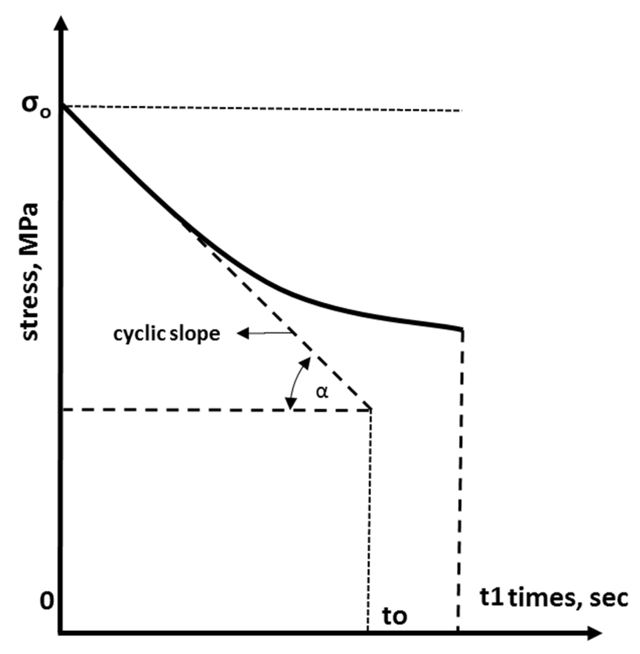
2. Stress Relaxation
3. Materials and Methods
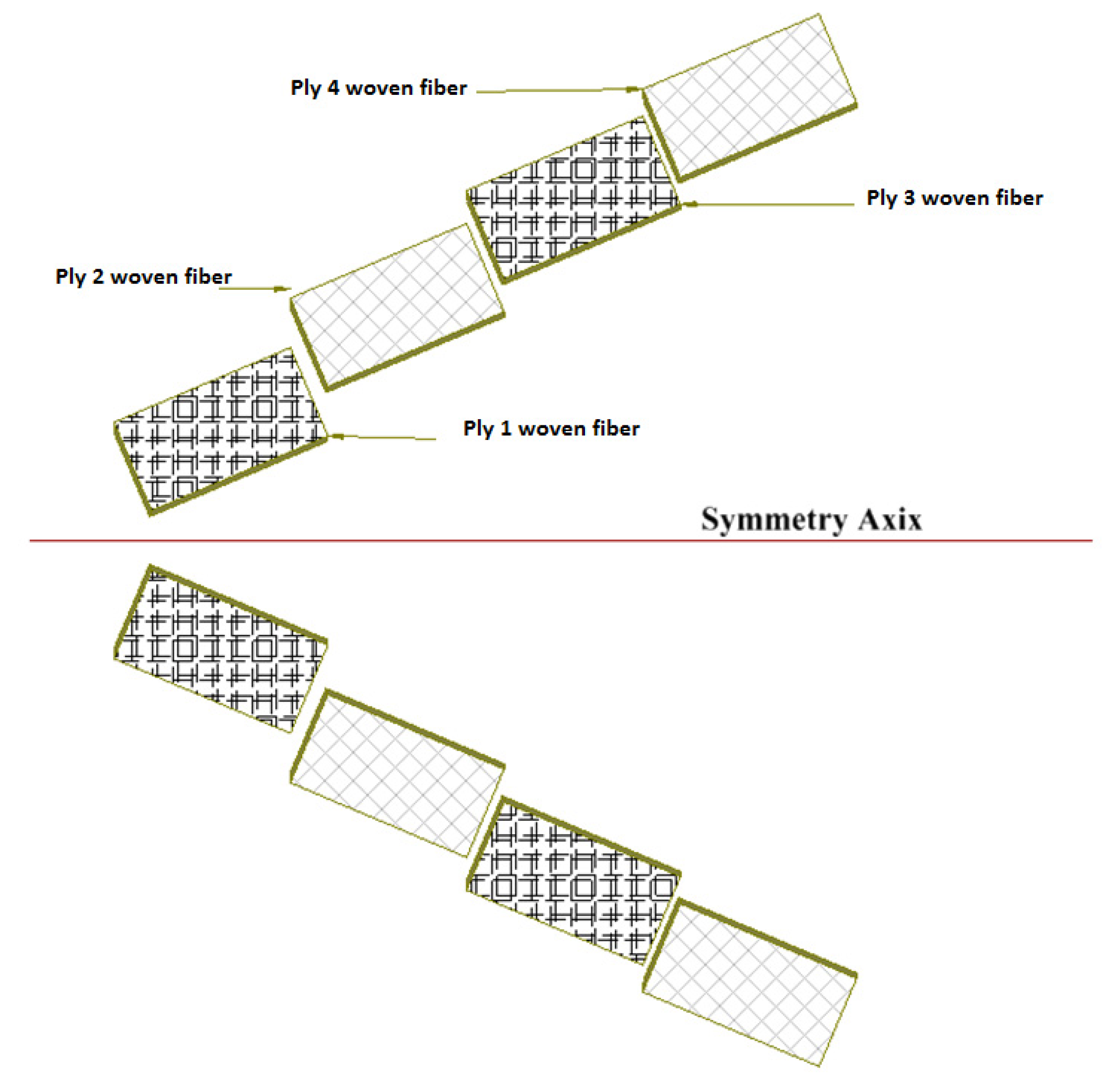
3.1. Hand Layup
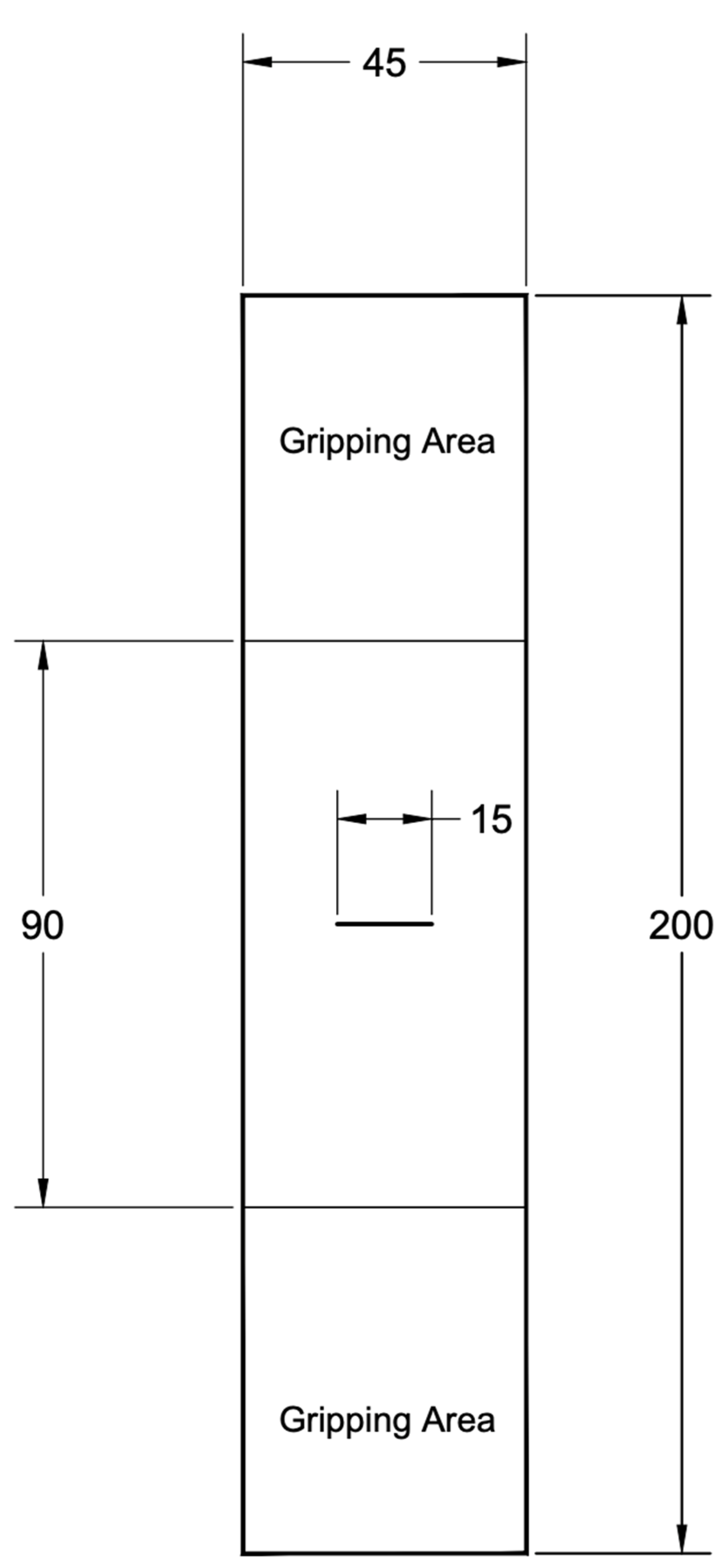
3.2. Tensile Test
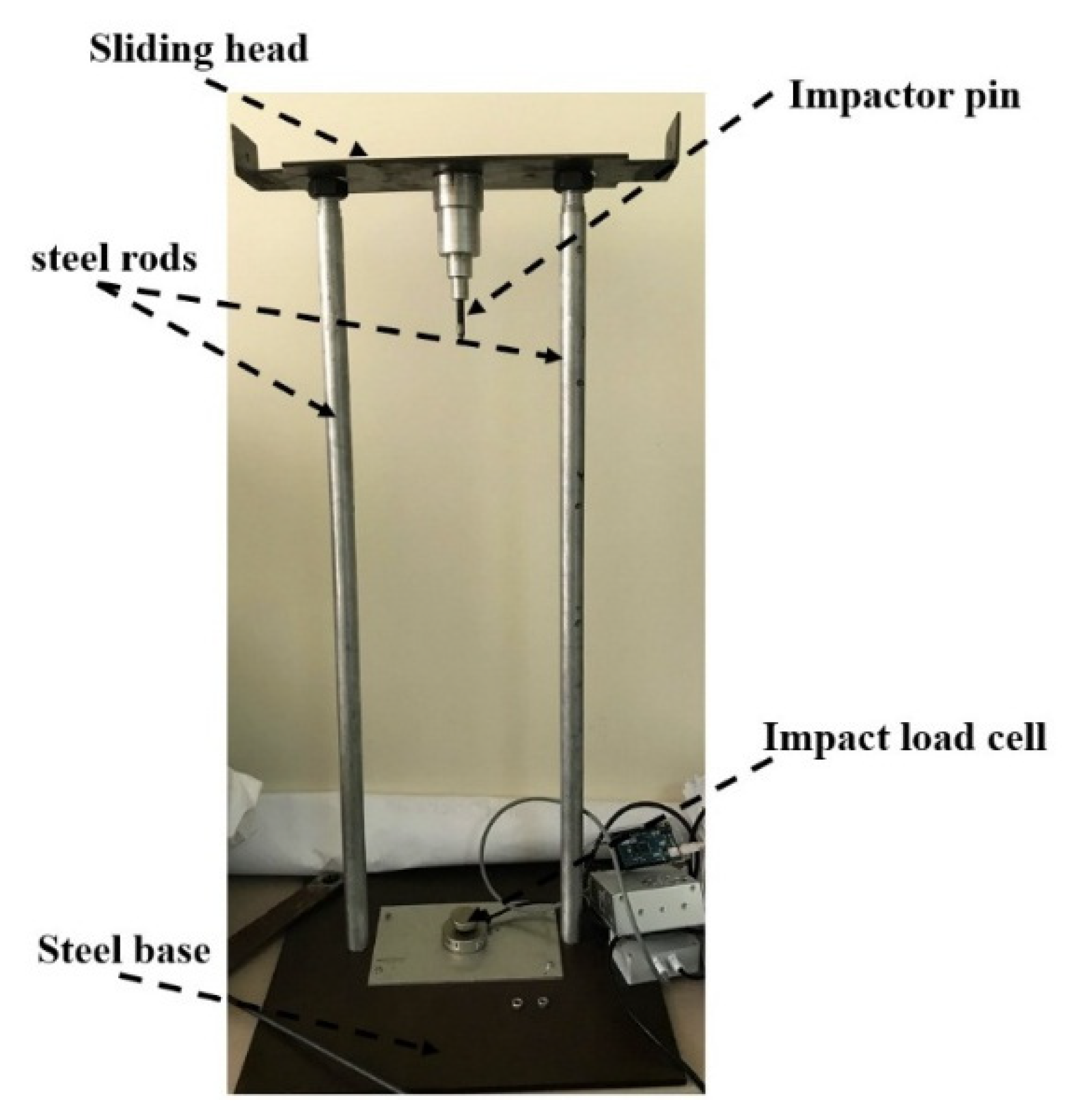
3.3. Drop Weight Impact Test
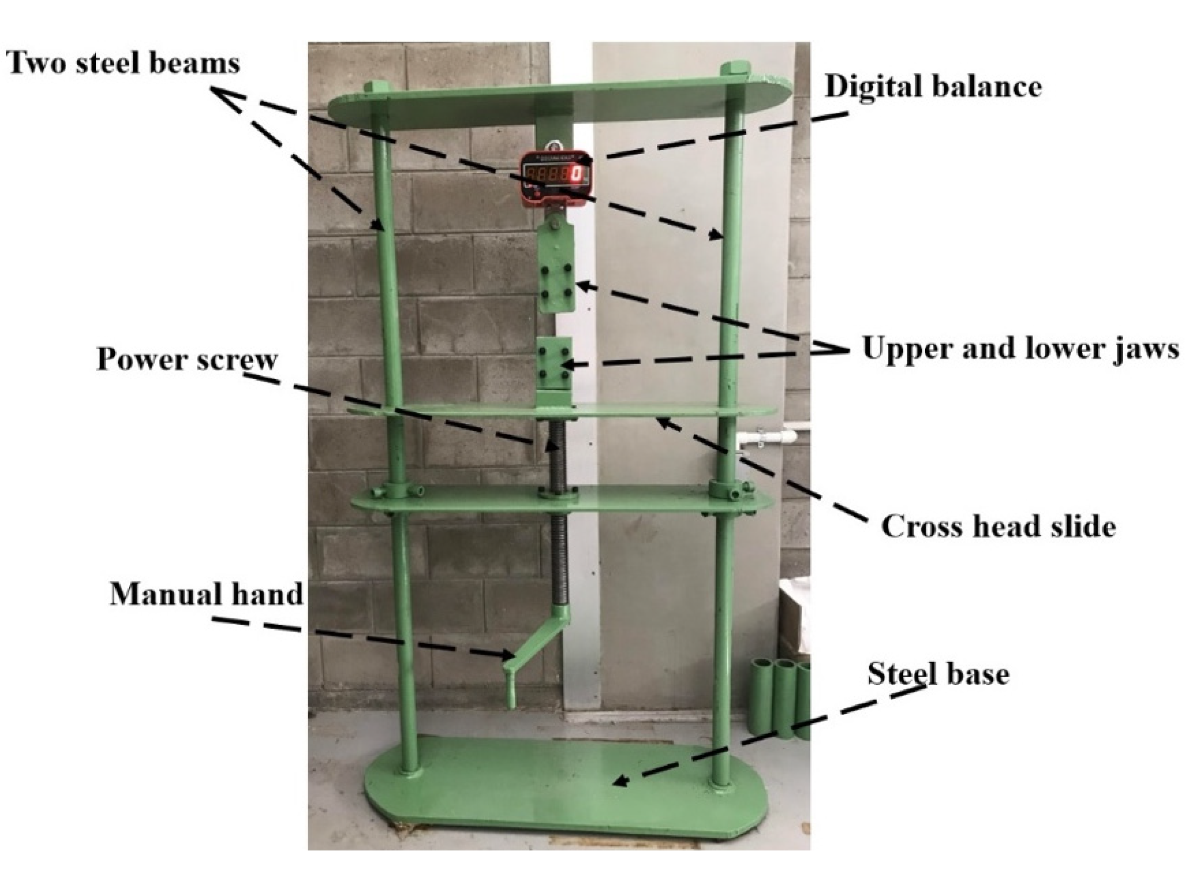
3.4. Relaxation Test
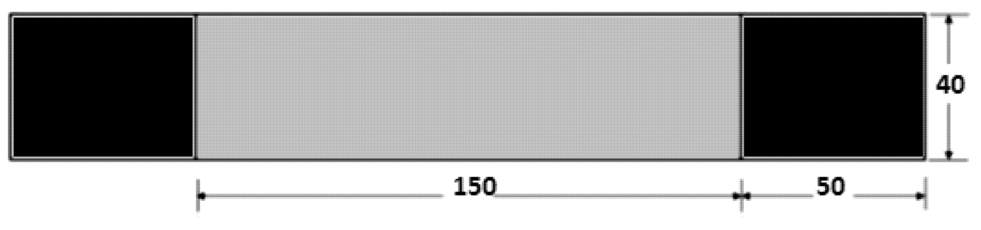
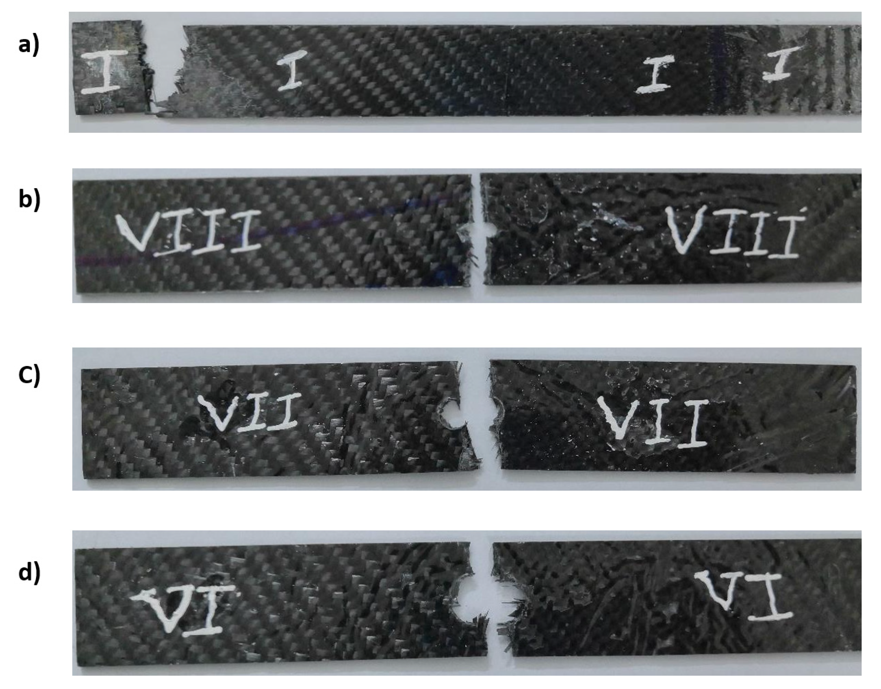
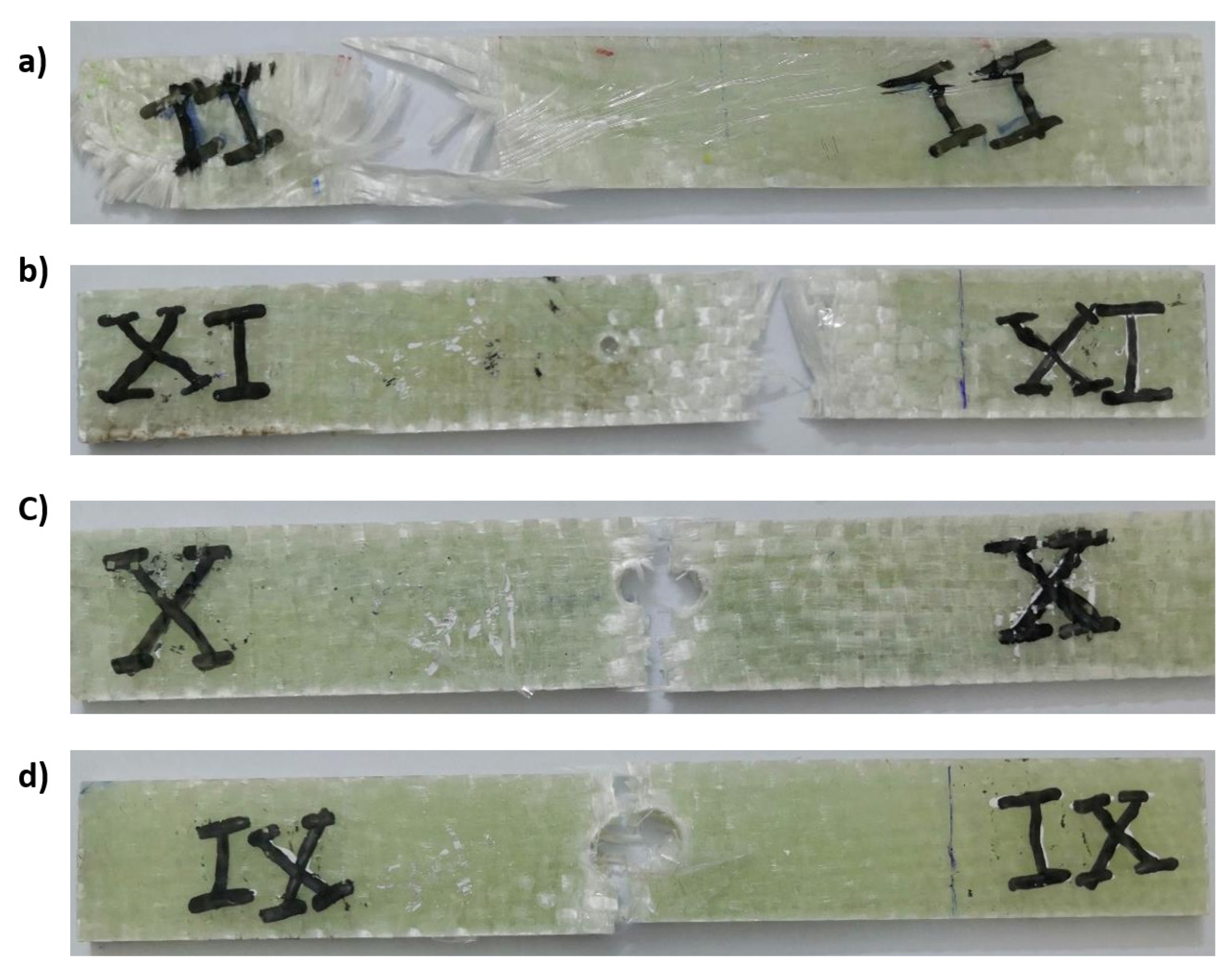
4. Center Notch Specimen
5. Results and Discussion
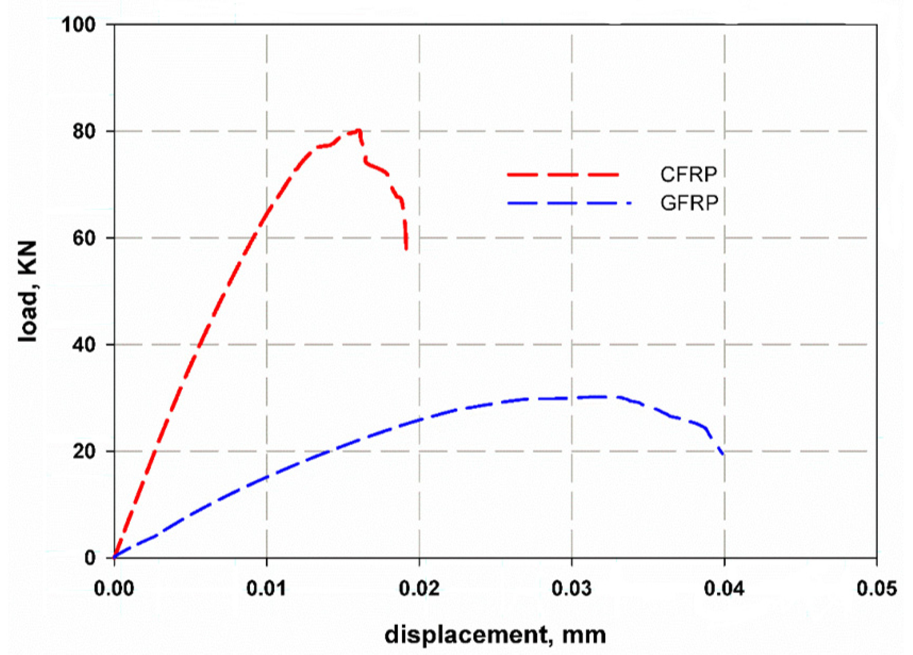
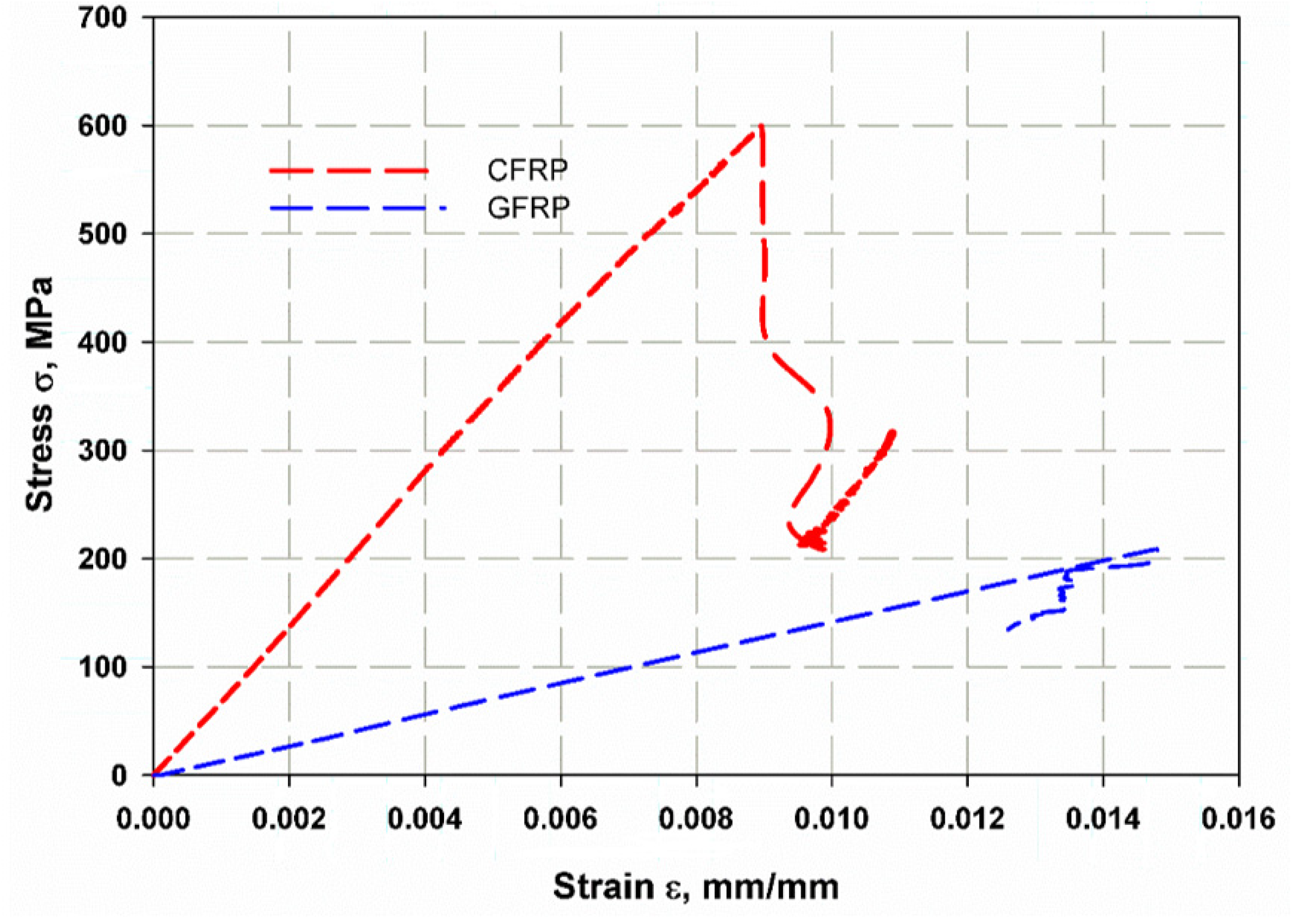
5.1. Tension Test
5.2. Center Crack Notch
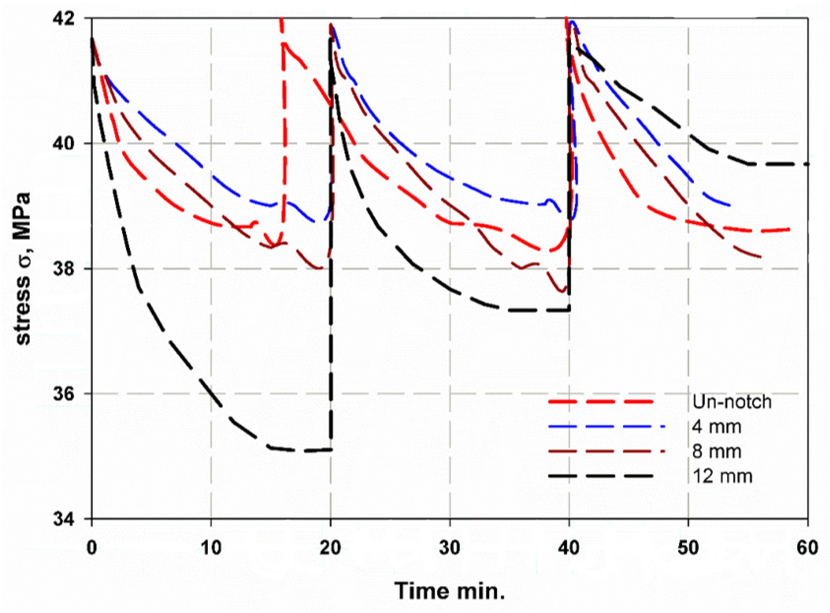
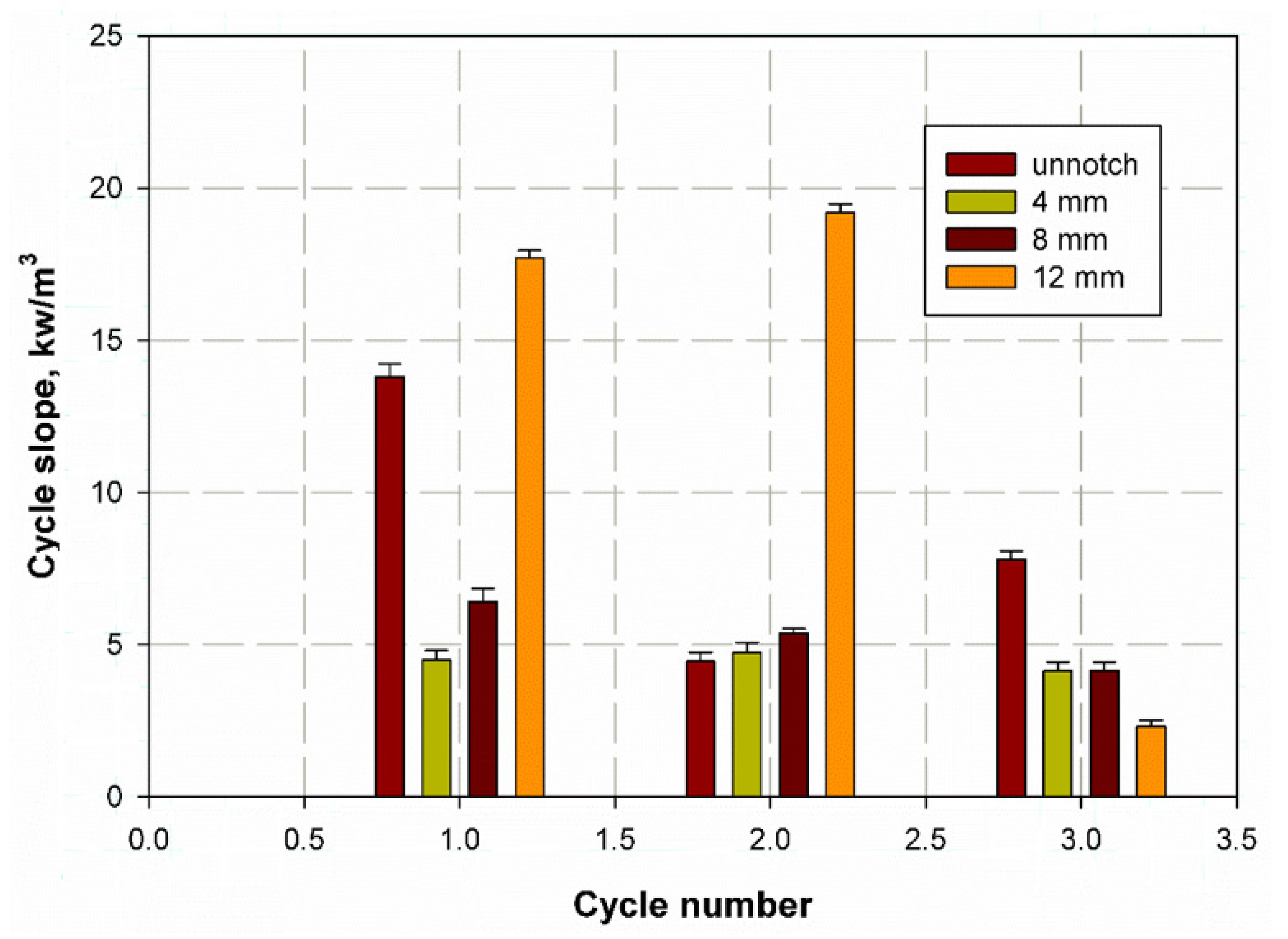
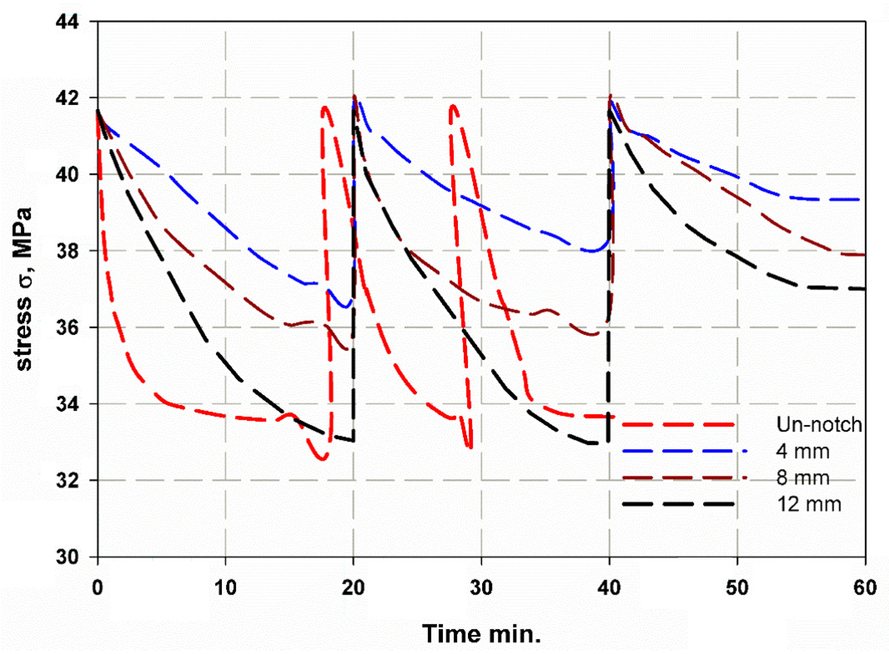
5.3. Relaxation Test
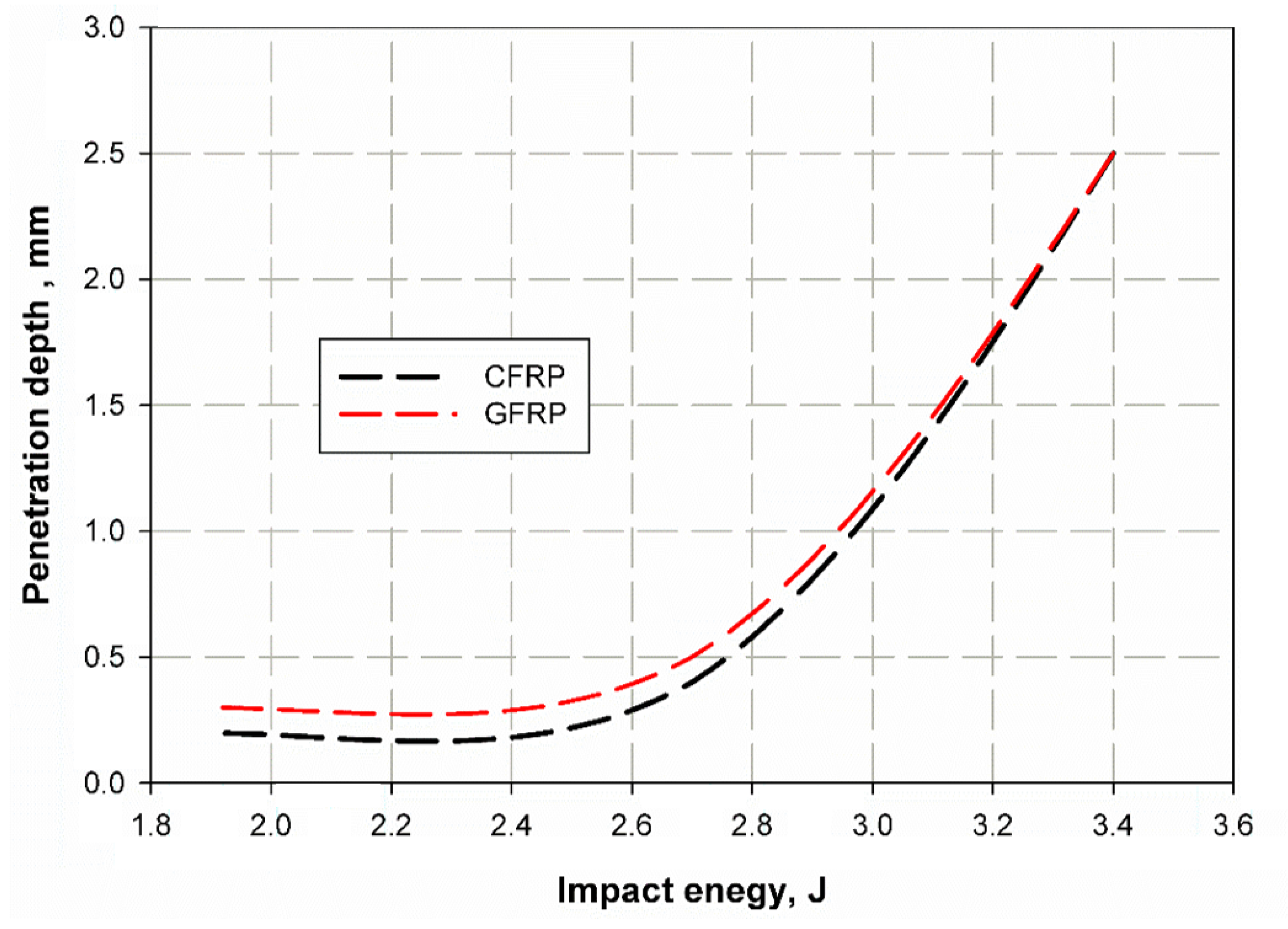
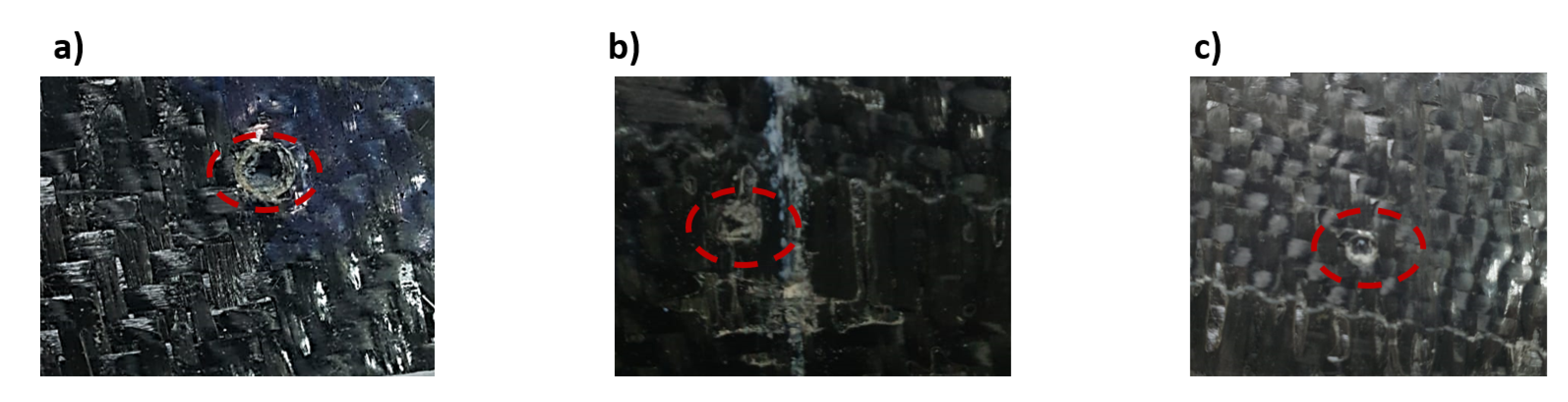
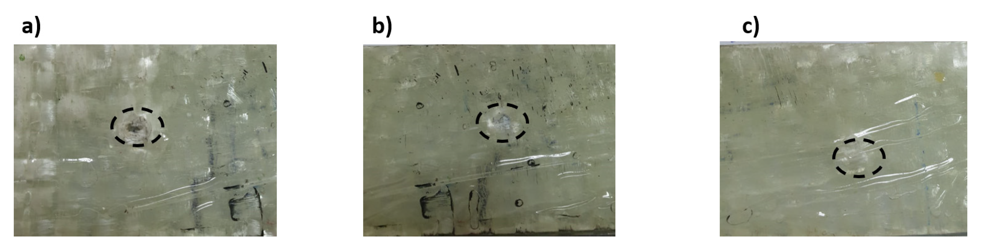
5.4. Drop Weight Impact Test
6. Concussions
Author Contributions
Funding
Institutional Review Board Statement
Informed Consent Statement
Data Availability Statement
Acknowledgments
Conflicts of Interest
References
- Abdellah, M.Y.; Alsoufi, M.S.; Hassan, M.K.; Ghulman, H.A.; Mohamed, A.F. Extended finite element numerical analysis of scale effect in notched glass fiber reinforced epoxy composite. Arch. Mech. Eng. 2015, 62, 2. [Google Scholar] [CrossRef] [Green Version]
- Alharthi, H.; Abdellah, M.Y.; Abdo, H.S.; Hassan, M.K. Size Effect and Fracture Toughness of Glass Fiber Composite Structures. Int. J. Adv. Sci. Technol. 2020, 29, 8567–8577. [Google Scholar]
- Mohammed, Y.; Hassan, M.K.; El-Ainin, H.A.; Hashem, A.M. Size Effect Analysis in Laminated Composite Structure using General Bilinear Fit. Int. J. Nonlinear Sci. Numer. Simul. 2013, 14, 217–224. [Google Scholar] [CrossRef]
- Mohammed, Y.; Hassan, M.K.; El-Ainin, H.A.; Hashem, A.M. Size effect analysis of open-hole glass fiber composite laminate using two-parameter cohesive laws. Acta Mech. 2015, 226, 1027–1044. [Google Scholar] [CrossRef]
- Guo, R.; Xian, G.; Li, C.; Huang, X.; Xin, M. Effect of fiber hybridization types on the mechanical properties of carbon/glass fiber reinforced polymer composite rod. Mech. Adv. Mater. Struct. 2021, 28, 1–13. [Google Scholar] [CrossRef]
- Xian, G.; Guo, R.; Li, C.; Hong, B. Effects of rod size and fiber hybrid mode on the interface shear strength of carbon/glass fiber composite rods exposed to freezing-thawing and outdoor environments. J. Mater. Res. Technol. 2021, 14, 2812–2831. [Google Scholar] [CrossRef]
- Abdellah, M.Y.; Sulaiman, S.; Mohamed, A.F.; Gomaa, A.A.; Abdel-Jaber, G.T. Relaxation, Impact and Flexural Properties of Glass Fiber Reinforced Epoxy. Int. J. Mech. Mechatron. Eng. IJMME-IJENS 2019, 19, 126–131. [Google Scholar]
- Abdellah, M.Y.; Mohamed, A.F.; Hasan, M.K. Characteristic Analysis: Vibration Behaviour of Composite Laminated Structures Compared to Monotonic Materials. Int. J. Mech. Mechatron. Eng. IJMME-IJENS 2019, 19, 57–69. [Google Scholar]
- Fouad, H.; Mourad, A.H.I.; ALshammari, B.A.; Hassan, M.K.; Abdallah, M.Y.; Hashem, M. Fracture toughness, vibration modal analysis and viscoelastic behavior of Kevlar, glass, and carbon fiber/epoxy composites for dental-post applications. J. Mech. Behav. Biomed. Mater. 2020, 101, 103456. [Google Scholar] [CrossRef] [PubMed]
- Mohammed, Y.; Hassan, M.K.; Hashem, A. Analytical model to predict multiaxial laminate fracture toughness from 0 ply fracture toughness. Polym. Eng. Sci. 2014, 54, 234–238. [Google Scholar] [CrossRef]
- Gong, Y.; Zhao, L.; Zhang, J.; Hu, N.; Zhang, C. Development of a standardized test procedure and an improved data reduction method for the mixed-mode I/II delamination in composite laminates. Compos. Sci. Technol. 2021, 201, 108488. [Google Scholar] [CrossRef]
- Ouyang, T.; Sun, W.; Bao, R.; Tan, R. Effects of matrix cracks on delamination of composite laminates subjected to low-velocity impact. Compos. Struct. 2021, 262, 113354. [Google Scholar] [CrossRef]
- Staniszewski, J.M.; Boyd, S.E.; Bogetti, T.A. A multi-scale modeling approach for UHMWPE composite laminates with application to low-velocity impact loading. Int. J. Impact Eng. 2022, 159, 104031. [Google Scholar] [CrossRef]
- Papanicolaou, G.; Zaoutsos, S. Viscoelastic constitutive modeling of creep and stress relaxation in polymers and polymer matrix composites. In Creep and Fatigue in Polymer Matrix Composites; Elsevier: Amsterdam, The Netherlands, 2019; pp. 3–59. [Google Scholar]
- Eftekhari, M.; Fatemi, A. On the strengthening effect of increasing cycling frequency on fatigue behavior of some polymers and their composites: Experiments and modeling. Int. J. Fatigue 2016, 87, 153–166. [Google Scholar] [CrossRef]
- Eftekhari, M.; Fatemi, A. Creep behavior and modeling of neat, talc-filled, and short glass fiber reinforced thermoplastics. Compos. Part B Eng. 2016, 97, 68–83. [Google Scholar] [CrossRef]
- Obaid, N.; Kortschot, M.T.; Sain, M. Understanding the stress relaxation behavior of polymers reinforced with short elastic fibers. Materials 2017, 10, 472. [Google Scholar] [CrossRef] [PubMed] [Green Version]
- George, J.; Sreekala, M.S.; Thomas, S.; Bhagawan, S.S.; Neelakantan, N.R. Stress relaxation behavior of short pineapple fiber reinforced polyethylene composites. J. Reinf. Plast. Compos. 1998, 17, 651–672. [Google Scholar] [CrossRef]
- Pothan, L.A.; Neelakantan, N.R.; Rao, B.; Thomas, S. Stress relaxation behavior of banana fiber-reinforced polyester composites. J. Reinf. Plast. Compos. 2004, 23, 153–165. [Google Scholar] [CrossRef]
- Obaid, N.; Kortschot, M.T.; Sain, M. Modeling and predicting the stress relaxation of composites with short and randomly oriented fibers. Materials 2017, 10, 1207. [Google Scholar] [CrossRef]
- Saeed, U.; Al-Turaif, H.; Siddiqui, M.E. Stress relaxation performance of glass fiber-reinforced high-density polyethylene composite. Polym. Polym. Compos. 2021, 29, 705–713. [Google Scholar] [CrossRef]
- Arif, M.; Saintier, N.; Meraghni, F.; Fitoussi, J.; Chemisky, Y.; Robert, G. Multiscale fatigue damage characterization in short glass fiber reinforced polyamide-66. Compos. Part B Eng. 2014, 61, 55–65. [Google Scholar] [CrossRef] [Green Version]
- Sato, N.; Kurauchi, T.; Sato, S.; Kamigaito, O. Microfailure behaviour of randomly dispersed short fibre reinforced thermoplastic composites obtained by direct SEM observation. J. Mater. Sci. 1991, 26, 3891–3898. [Google Scholar] [CrossRef]
- Pérez-Pacheco, E.; Moreno-Chulim, M.V.; Valadez-González, A.; Rios-Soberanis, C.R.; Herrera-Franco, P.J. Effect of the interphase microstructure on the behavior of carbon fiber/epoxy resin model composite in a thermal environment. J. Mater. Sci. 2011, 46, 4026–4033. [Google Scholar] [CrossRef]
- Ma, L.; Meng, L.; Wu, G.; Wang, Y.; Zhao, M.; Zhang, C.; Huang, Y. Effects of bonding types of carbon fibers with branched polyethyleneimine on the interfacial microstructure and mechanical properties of carbon fiber/epoxy resin composites. Compos. Sci. Technol. 2015, 117, 289–297. [Google Scholar] [CrossRef]
- Wu, G.; Ma, L.; Liu, L.; Wang, Y.; Xie, F.; Zhong, Z.; Zhao, M.; Jiang, B.; Huang, Y. Interfacially reinforced methylphenylsilicone resin composites by chemically grafting multiwall carbon nanotubes onto carbon fibers. Compos. Part B Eng. 2015, 82, 50–58. [Google Scholar] [CrossRef]
- Varghese, S.; Kuriakose, B.; Thomas, S. Stress relaxation in short sisal-fiber-reinforced natural rubber composites. J. Appl. Polym. Sci. 1994, 53, 1051–1060. [Google Scholar]
- Ahmed, F.M.; Mohammed, Y.A.; Mohammed, K.H. Relaxation and Compressive Characteristic in Composite Glass Fiber reinforced Pipes. Int. J. Sci. Eng. Res. 2015, 6, 1823–1827. Available online: https://www.ijser.org/onlineResearchPaperViewer.aspx?Relaxation-and-Compressive-Characteristic-in-Composite-Glass-Fiber-reinforced-Pipes.pdf (accessed on 2 November 2021).
- Ornaghi, H.L., Jr.; Almeida, J.H.S., Jr.; Monticeli, F.M.; Neves, R.M. Stress relaxation, creep, and recovery of carbon fiber non-crimp fabric composites. Compos. Part C Open Access 2020, 3, 100051. [Google Scholar] [CrossRef]
- Tobushi, H.; Matsui, R.; Takeda, K.; Hayashi, S. Mechanical testing of shape-memory polymers for biomedical applications. In Shape Memory Polymers for Biomedical Applications; Woodhead Publishing: Sawston, UK, 2015; pp. 65–75. [Google Scholar]
- Khashaba, U.A. In-plane shear properties of cross-ply composite laminates with different off-axis angles. Compos. Struct. 2004, 65, 167–177. [Google Scholar] [CrossRef]
- Mohammed, Y.; Hassan, M.K.; Hashem, A.M. Effect of stacking sequence and geometric scaling on the brittleness number of glass fiber composite laminate with stress raiser. Sci. Eng. Compos. Mater. 2014, 21, 281–288. [Google Scholar] [CrossRef]
- Hassan, M.K.; Abdellah, M.Y.; Azabi, S.K.; Marzouk, W.W. Fracture Toughness of a Novel GLARE Composite Material. Int. J. Eng. Technol. IJET-IJENS 2015, 15, 36–41. [Google Scholar]
- Korim, N.S.; Abdellah, M.Y.; Dewidar, M.; Abdelhaleem, A.M. Crushable Finite Element Modeling of Mechanical Properties of Titanium Foam. Int. J. Sci. Eng. Res. 2015, 6, 1221–1227. [Google Scholar]
- Mohamed, K.; Hassan, Y.M.; Abu El-Ainin, H. Improvement of Al-6061 alloys mechanical properties by controlling processing parameters. Int. J. Mech. Mechatron. Eng. IJMME-IJENS 2012, 12, 14–18. [Google Scholar]
- Hassan, M.K.; Abdellah, M.Y.; Azabi, S.K.; Marzouk, W. Investigation of the Mechanical Behavior of Novel Fiber Metal Laminates. Int. J. Mech. Mechatron. Eng. IJMME-IJENS 2015, 15, 112–118. [Google Scholar]
- Hagnestål, A.; Sellgren, U.; Andersson, K. Durable winch-based point absorbers. In Proceedings of the Ewtec 2017: The 12th European Wave and Tidal Energy Conference, Cork, Ireland, 27 August–1 September 2017. [Google Scholar]
- Shukla, M.J.; Kumar, D.S.; Mahato, K.K.; Rathore, D.; Prusty, R.K.; Ray, B.C. A comparative study of the mechanical performance of Glass and Glass/Carbon hybrid polymer composites at different temperature environments. IOP Conf. Ser. Mater. Sci. Eng. 2015, 75. [Google Scholar] [CrossRef] [Green Version]
- ASTM D3171. Standard Test Methods for Constituent Content of Composite Materials; ASTM International: West Conshohocken, PA, USA, 2011. [Google Scholar]
- Available online: http://www.victorytest.com/products/wdw-50100-and-computerized-electromechanical-universal-testing-machine (accessed on 11 February 2021).
- ASTM D3039/D 3039M. Standard Test Method for Tensile Properties of Polymer Matrix Composite Materials; ASTM International: West Conshohocken, PA, USA, 1995. [Google Scholar]
- Taheri-Behrooz, F.; Shokrieh, M.M.; Abdolvand, H. Designing and manufacturing of a drop weight impact test machine. Eng. Solid Mech. 2013, 1, 69–76. [Google Scholar] [CrossRef]
- Swallowe, G.M. Mechanical Properties and Testing of Polymers: An A–Z reference; Springer Science & Business Media: Berlin, Germany, 1999; Volume 3. [Google Scholar]
- Meyers, M.A.; Chawla, K.K. Mechanical Behavior of Materials; Cambridge University Press: Cambridge, UK, 2008. [Google Scholar]
- Rutter, E.; Atkinson, B.; Mainprice, D. On the use of the stress relaxation testing method in studies of the mechanical behaviour of geological materials. Geophys. J. Int. 1978, 55, 155–170. [Google Scholar] [CrossRef] [Green Version]
- Soutis, C.; Curtis, P.T.; Fleck, N.A. Compressive failure of notched carbon fibre composites. Proc. R. Soc. Lond. Ser. A Math. Phys. Sci. 1993, 440, 241–256. [Google Scholar]


Publisher’s Note: MDPI stays neutral with regard to jurisdictional claims in published maps and institutional affiliations. |
© 2021 by the authors. Licensee MDPI, Basel, Switzerland. This article is an open access article distributed under the terms and conditions of the Creative Commons Attribution (CC BY) license (https://creativecommons.org/licenses/by/4.0/).
Share and Cite
Abdellah, M.Y.; Hassan, M.K.; Mohamed, A.F.; Backar, A.H. Cyclic Relaxation, Impact Properties and Fracture Toughness of Carbon and Glass Fiber Reinforced Composite Laminates. Materials 2021, 14, 7412. https://doi.org/10.3390/ma14237412
Abdellah MY, Hassan MK, Mohamed AF, Backar AH. Cyclic Relaxation, Impact Properties and Fracture Toughness of Carbon and Glass Fiber Reinforced Composite Laminates. Materials. 2021; 14(23):7412. https://doi.org/10.3390/ma14237412
Chicago/Turabian StyleAbdellah, Mohammed Y., Mohamed K. Hassan, Ahmed F. Mohamed, and Ahmed H. Backar. 2021. "Cyclic Relaxation, Impact Properties and Fracture Toughness of Carbon and Glass Fiber Reinforced Composite Laminates" Materials 14, no. 23: 7412. https://doi.org/10.3390/ma14237412
APA StyleAbdellah, M. Y., Hassan, M. K., Mohamed, A. F., & Backar, A. H. (2021). Cyclic Relaxation, Impact Properties and Fracture Toughness of Carbon and Glass Fiber Reinforced Composite Laminates. Materials, 14(23), 7412. https://doi.org/10.3390/ma14237412