Article

Effect of Electrolytic Manganese Residue in Fly Ash-Based Cementitious Material: Hydration Behavior and Microstructure

1
State Key Laboratory of Advanced Metallurgy, School of Metallurgical and Ecological Engineering, University of Science and Technology Beijing, Beijing 100083, China
2
Beijing Key Laboratory of Materials Utilization of Nonmetallic Minerals and Solid Wastes, National Laboratory of Mineral Materials, School of Materials Science and Technology, China University of Geosciences, Beijing 100083, China
*
Authors to whom correspondence should be addressed.
Materials 2021, 14(22), 7047; https://doi.org/10.3390/ma14227047
Submission received: 30 August 2021 / Revised: 6 November 2021 / Accepted: 16 November 2021 / Published: 20 November 2021

Abstract

:
Electrolytic manganese residue (EMR) is a solid waste with a main mineralogical composition of gypsum. It is generated in the production of metal manganese by the electrolysis process. In this research, EMR, fly ash, and clinker were blended to make fly ash-based cementitious material (FAC) to investigate the effect of EMR on strength properties, hydration behavior, microstructure, and environmental performance of FAC. XRD, TG, and SEM studied the hydration behavior of FAC. The pore structure and [SiO4] polymerization degree were characterized by MIP and 29Si NMR, respectively. The experimental results indicate that FAC shows excellent mechanical properties when the EMR dosage is 10%. Moderate content of sulfate provided by EMR can promote hydration reaction of FAC, and it shows a denser pore structure and higher [SiO4] polymerization degree in this case. Heavy metal ions derived from EMR can be adsorbed in the hydration products of FAC to obtain better environmental properties. This paper presents an AFt covering model for the case of excessive EMR in FAC, and it importantly provides theoretical support for the recycling of EMR in cementitious materials.

Graphical Abstract

1. Introduction

Electrolytic manganese residue (EMR) is the main kind of solid waste generated in the production of metal manganese by the electrolysis process [1]. About 6–9 tons of EMR is produced with the production of per ton of manganese [2]. The prime hazardous substances in EMR are ammonia nitrogen (NH3-N) and manganese ion, leading to serious environmental pollution problems [3,4,5]. Although electrolytic manganese plants have used many different methods to dispose of EMR, the environmental pollution problem is still serious [6,7]. Therefore, rational recycling and utilization of EMR can alleviate the environmental problems caused by EMR and bring good environmental benefits to society. The electrolytic manganese enterprises will obtain good economic benefits as well [8].
Quartz and gypsum are the main mineral components in EMR. The difference between EMR and other slags is that EMR is rich in sulfate. According to the detection, the content of SO3 in EMR reaches 30% [9]. The sulfate in EMR exists in many forms, not limited to gypsum. For example, it can be found in ammonium sulfate and manganese sulfate [10]. In recent years, great progress has been achieved in the recycling of EMR. Preparation of building materials is a valid way for the recycling of EMR. Li et al. [11] found that if using EMR and fly ash to prepare a composite admixture, the strength of the cement system will be improved with the adding of calcined EMR. Moreover, EMR can be used as a raw material to produce sulfoaluminate-like cement [12] and sulfur concrete [13]. At present, the application of EMR in building materials is simply blended into cement and concrete. However, the effect of sulfate in EMR has not been considered in these researches [14,15,16].
Fly ash is one of the largest industrial solid wastes in the world. SiO2, Al2O3, Fe2O3, and CaO are the main chemical composition in fly ash [17,18]. It is a composite structure composed of crystal and amorphous phases under the microscope. Crystal phases include quartz, mullite, magnetite, etc. Amorphous phases include smooth spherical vitreous particles, small particles with irregular pore shapes, porous and irregular vitreous spheres [19]. Fly ash belongs to an artificial pozzolanic material that shows good cementitious activity in lime and gypsum solutions. Its cementitious activity mainly comes from the hydration of active SiO2 and active Al2O3 in the vitreous phases under certain alkaline conditions. Therefore, fly ash is commonly used as a cement admixture for its potential pozzolanic activity [20].
In previous studies [21,22,23], desulfurization gypsum or phosphogypsum has been applied to cement as a cement retarder because its main component is CaSO4·2H2O. It can react with calcium aluminate (C3A) in cement clinker to form ettringite and delay the setting time. Xu et al. [24] studied the effect of sulfate on the hydration characteristics of blast furnace slag. The results showed that a proper amount of sulfate could facilitate the reaction of blast furnace slag to produce C-S-H gel and AFt, which makes cementitious material’s internal structure more compact. Li et al. [25] studied the effect of gypsum on the working and mechanical properties of red mud and blast furnace slag-based cementitious materials. The results showed that different kinds of gypsum could reduce the fluidity of mortar, shorten the setting time, and improve the mechanical properties of mortar. It is worth noting that previous studies focused more on the effect of sulfate on the hydration of blast furnace slag by using desulfurized gypsum or phosphogypsum, which provides an effective reference for the utilization of EMR in cementitious materials. Although there is no effective way to use EMR, it contains a certain amount of sulfate. In addition, when electrolytic manganese slag is used as supplementary cementitious material, it contains many heavy metal salts, which must also be paid attention to.
In this work, EMR, fly ash, and clinker were used to prepare fly ash-based cementitious material (FAC) to investigate the effect of EMR with different dosages on the mechanical properties, hydration behavior, microstructure, and environmental performance of FAC. The hydration behavior was characterized by scanning electron microscopy (SEM), X-ray diffraction (XRD), and thermogravimetric analysis (TG). The pore structure and [SiO4] polymerization degree were analyzed by mercury intrusion porosimetry (MIP) and 29Si nuclear magnetic resonance (NMR), respectively. The environmental performance was analyzed by a heavy metal leaching test. This work helps to understand the real roles of EMR in cementitious materials. It is conducive to solving environmental problems through the effective utilization of EMR in construction and building materials.

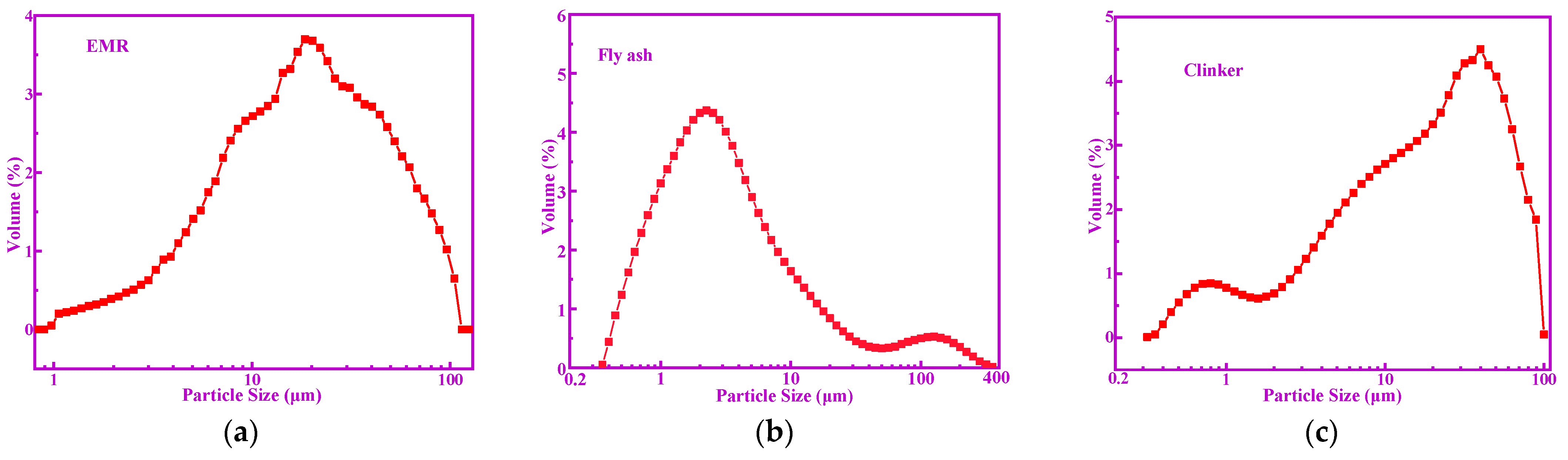
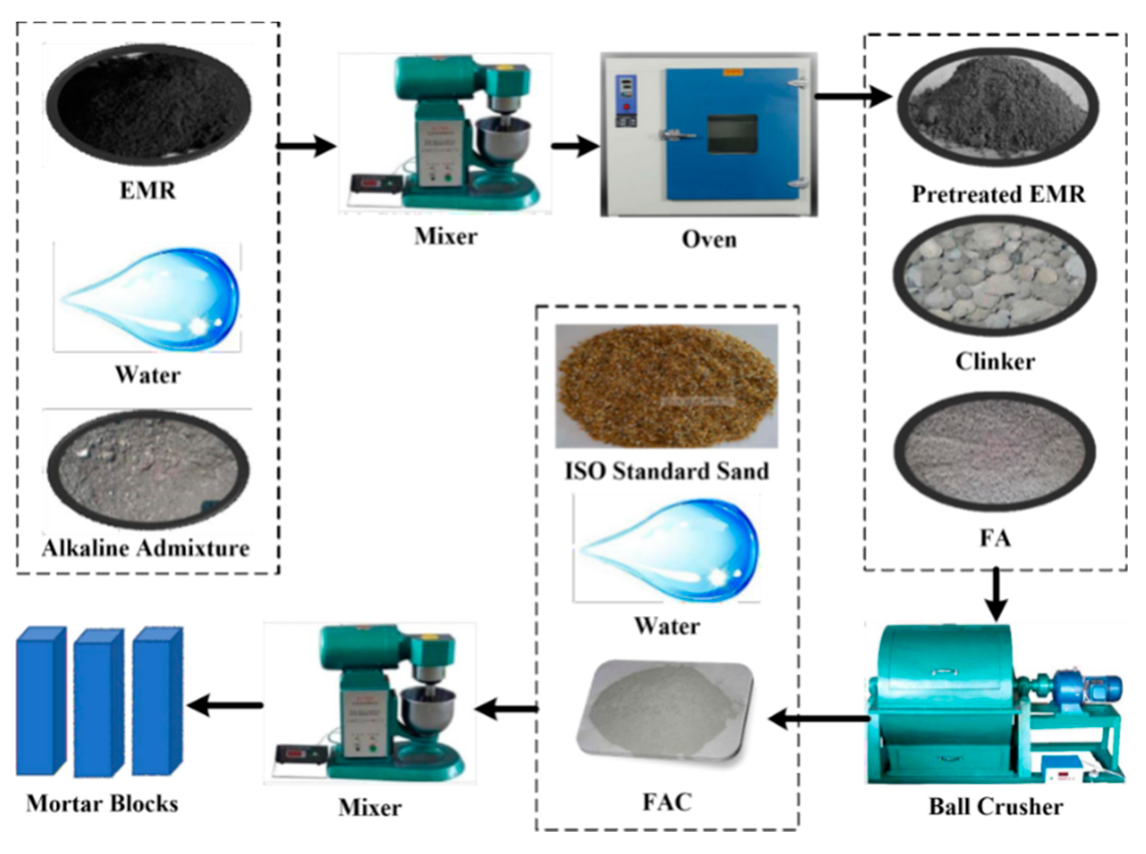
2. Materials and Methods

EMR used in this work is the waste residue of an electrolytic manganese plant (Songtao Sanhe Manganese Industry Group Co., Ltd.) in Tongren, Guizhou province of China, and its color is black. Fly ash (FA) was also supplied by a power plant (Dalong power plant) from Guizhou province of China. The clinker was obtained from a cement plant (Tangshan Jidong Cement Co., Ltd) in Tangshan, Hebei province of China, the strength grade of which is 42.5. Standard sand was obtained from China ISO Sand Co., Ltd (Beijing, China). Table 1 shows the chemical composition of raw materials, in which EMR presents a high content of SO3 close to 30%. The specific surface areas of the FA, EMR, and clinker were 568.58 m2/kg, 610.73 m2/kg, and 454.27 m2/kg, respectively. The particle size distribution of raw materials is shown in Figure 1 (EMR: d50 = 15.24 μm; FA: d50 = 2.59 μm; Clinker: d50 = 17.93 μm).
Previous studies have shown that it is necessary to pretreat EMR before it is used to reduce NH3-N content and solidify heavy metals [26]. In our experiment, a kind of alkaline admixture was used to pretreat EMR. The main component of this alkaline additive is carbide slag (The XRD spectrum of carbide slag is shown in Figure S1). Therefore, it can be used as lime to pretreat EMR. Firstly, EMR and alkaline admixture were mixed together at a 10:1 ratio, and then they were mixed well with water in a cement mortar mixer. Then they were dried in an oven until the mass no longer changed. The pretreated EMR, clinker, and FA were mixed as designed proportions are shown in Table 2. The raw materials were put into a ball crusher to mix and grind. After XRF (xrf-1800) analysis, the SO3 content in the resultant FAC can be obtained, and they are also listed in Table 2. It can be seen that the content of SO3 in the FAC samples increases obviously with the increasing dosage of EMR. An FBT-9 specific surface area tester obtained the fineness of FAC powder. The preparation process of FAC and mortar blocks is shown in Figure 2.
In order to investigate the effect of EMR on the mechanical properties of FAC, mortar blocks in size of 40 mm × 40 mm × 160 mm were prepared, in which the water/binder ratio was 0.5, and sand/binder ratio was 3. The mortar samples were kept in the curing box for maintenance for 24 h. The curing temperature was maintained at 25 ± 1 °C, and the humidity was 95 ± 1%. Then the mortar samples were released from the mold and placed in a maintenance pool, in which the water height was 2 cm taller than the upper surface of mortar samples. An automatic pressure testing machine obtained the mechanical properties of the FAC mortar samples.
In order to investigate the effect of EMR on the hydration characteristics and microstructure of FAC, paste samples in the size of 20 mm × 20 mm × 20 mm were prepared, in which the water/binder ratio was 0.35. The paste samples were cured for several days, and then they were taken out from the curing box for characterization. The hydration of paste samples was ended with absolute ethanol. After that, they were put in a vacuum drying box at 60 °C. The hardened paste after dehydrating with anhydrous ethanol and vacuum drying treatment can be used for MIP detection. These hardened pastes were ground for XRD, TG, and NMR analysis. The XRD data were recorded using a Bruker XRD-7000 diffractometer (Bruker, Beijing, China). The experimental conditions were 40 kV, 100 mA, Cu Target, and scanning speed of 4 °C/min. TG-DTG data were recorded by using a TGA 4000 thermogravimetric analyzer (PerkinElmer, Shanghai, China). The experimental conditions were N2, heating rate of 10 °C/min, and heating temperature range of 20 to 1000 °C. In the MIP analysis, the pore size distribution of the sample was measured by AutoPore IV 9500 automatic mercury injector (Micromeritics Instruments Corporation, Shanghai, China) at 25 °C and 60,000 psi (423,685 kpa). The high-pressure pore diameter analysis is a minimum 3 nm. The low-pressure analysis pressure range is 0.5–50 psia (3.45–310 kpa). The low-pressure aperture analysis range is 360–3.6 μm. The 29Si NMR spectroscopy was obtained by using Bruker ADVANCE III 600M spectrometer (Beijing, China) to study the [SiO4] polymerization degree of hydration products. The microstructure of FAC hydrated pastes was characterized by using a JEOL JSM-6701F scanning electron microscope (Beijing, China).

3. Results and Discussion

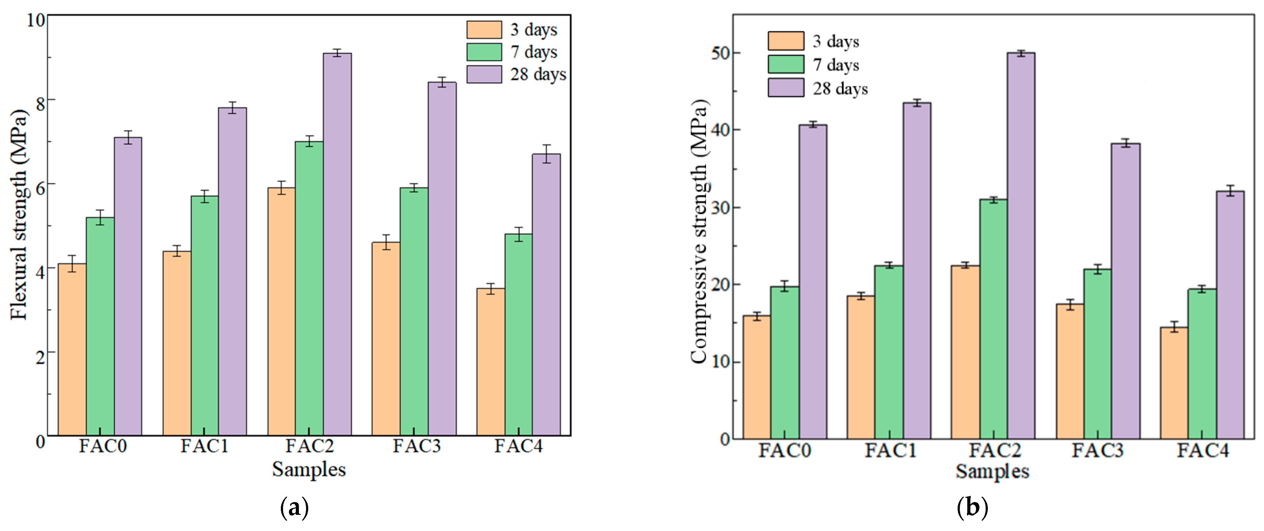
3.1. Effect of Electrolytic Manganese Residue on the Strength of FAC

In this experiment, the flexural strength and compressive strength of FAC mortar samples at 3d, 7d, and 28d were tested, and the results are recorded in Figure 3. As shown from Figure 3a,b, with the increase of EMR dosage, the peak values of flexural strength and compressive strength appeared at the EMR dosage of 10%. Meanwhile, as maintenance time increased from 3d to 28d, the strength was also enhanced. The best 3d compressive strength of 22.5 MPa and 28d compressive strength of 50 MPa were obtained by FAC2 sample. The compressive strength of FAC2 can even reach the strength level of 42.5R ordinary Portland cement.
As the maintenance time increases, the strength of FAC mortar samples increases, but the strength of FAC3 and FAC4 is still below that of FAC2. The reason could be complicated. First, EMR contains a considerable number of inert components. When the EMR dosage is excessive, the increasing inert components will weaken the cementation properties of the FAC system to weaken the compactness and reduce the strength of the mortar specimen. Second, excessive gypsum in EMR can inhibit the hydration reaction and hinder the growth of AFt. Meanwhile, excessive gypsum could also lead to volume expansion and poor volume stability in the later period, resulting in small cracks in the sample and affecting the strength of FAC. Therefore, a proper amount of EMR can stimulate the formation of hydration products and improve the compactness of hardened FAC, but excessive EMR will reduce the strength of FAC.
Considering that the strength of FAC4 containing 20% EMR is lower than that of 42.5 ordinary Portland cement, the effect of 20% EMR on the hydration characteristics and microstructure of FAC was ignored in the following analysis.

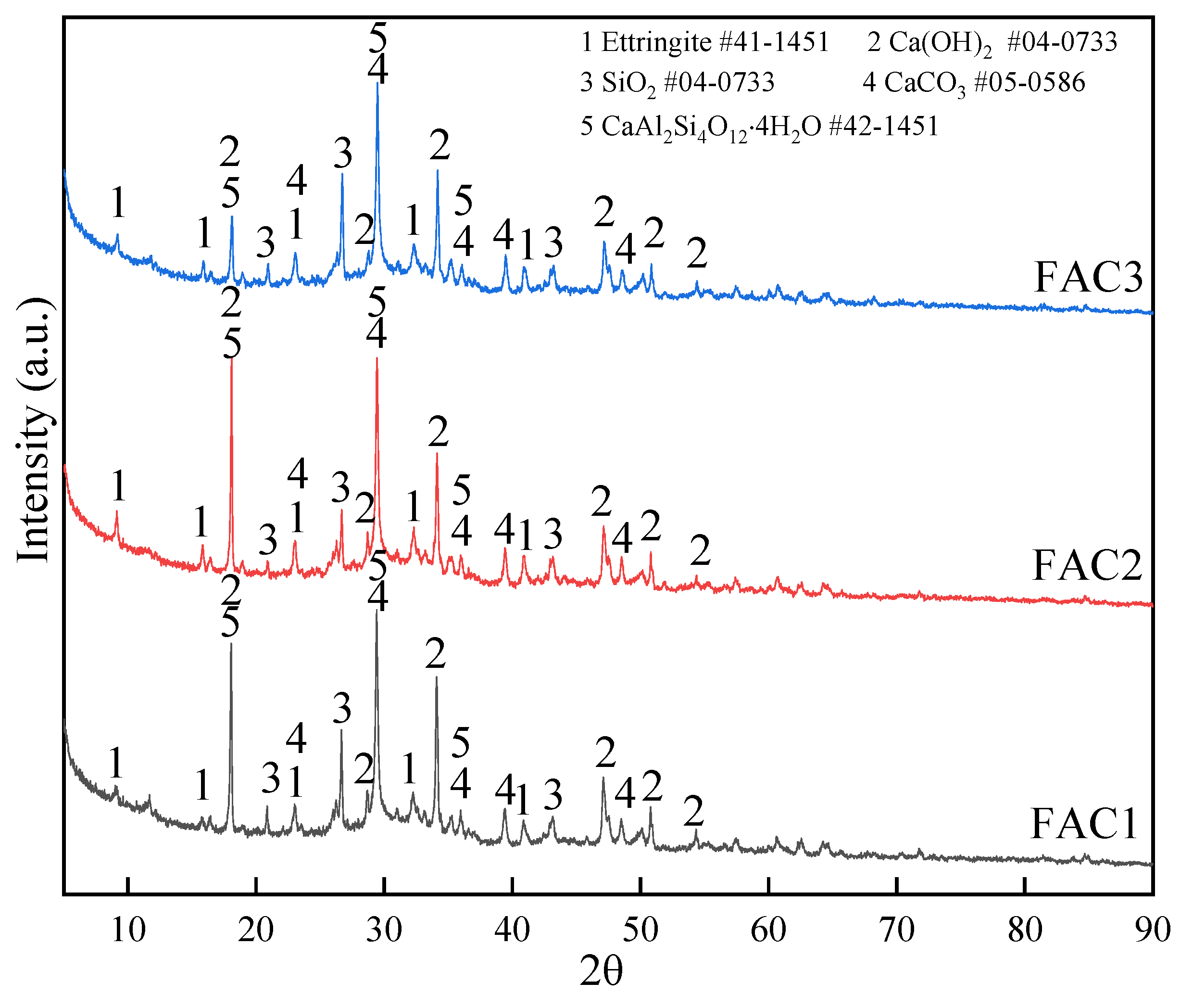
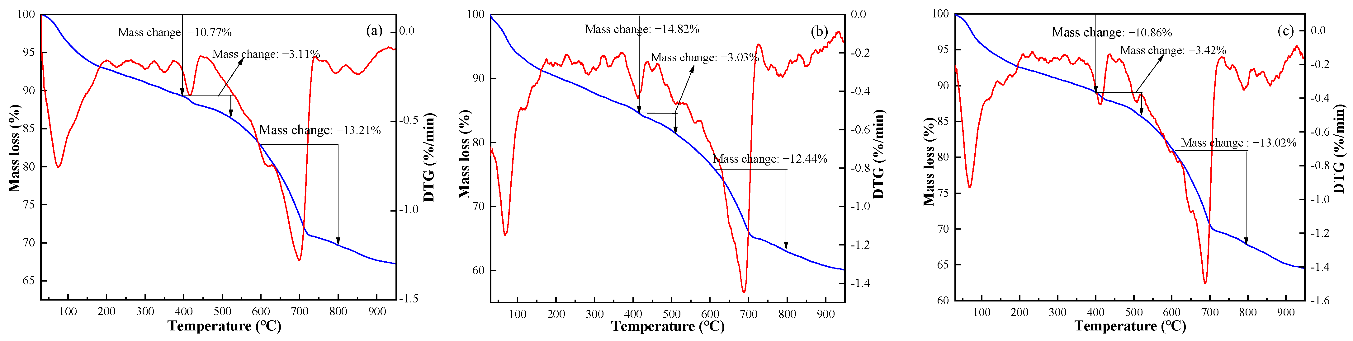
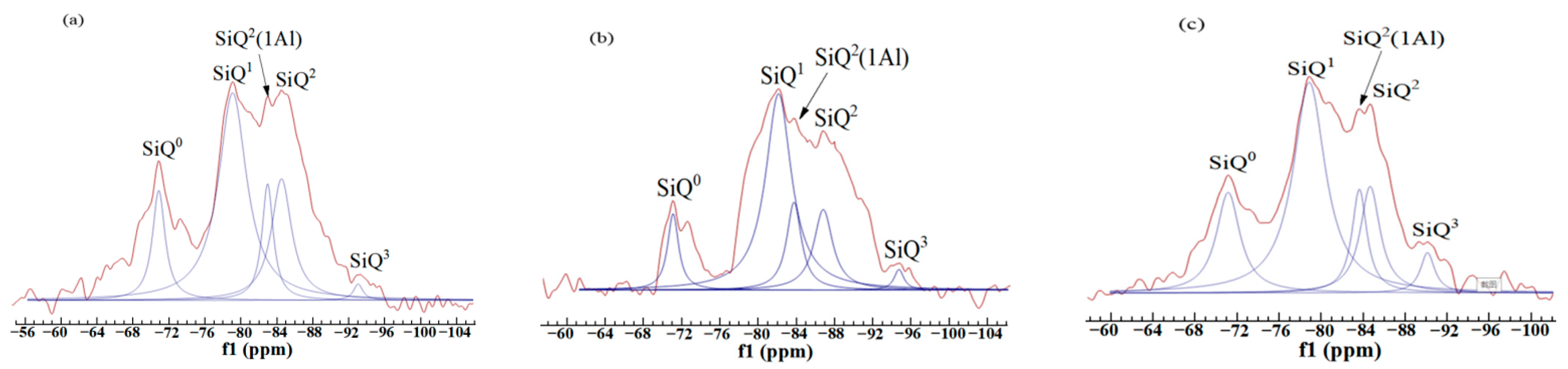
3.2. Effect of Electrolytic Manganese Residue on Hydration Products of FAC

The XRD patterns of FAC paste samples (FAC1, FAC2, and FAC3) hydrated at 28d are shown in Figure 4. The main crystalline phases are ettringite (Ca6Al2(SO4)3(OH)12·26H2O), CaCO3, and Ca(OH)2. Besides, there is also a kind of zeolite-like phase (CaAl2Si4O12·4H2O). The three XRD patterns present the dispersion peak between 23° and 37° indicative of amorphous compound C-A-S-H gels production. No diffraction peaks in the XRD spectrum are found for C-A-S-H gel and C-S-H gel because they are amorphous phases [27]. C-S-H gel and Ca(OH)2 are generally synthesized by the hydration of the clinker. The peak of CaCO3 is caused by partial carbonation of Ca(OH)2 and CaCO3 in the raw materials. The XRD spectrum of fly ash is shown in Figure S2. Moreover, the vitreous substances of fly ash can be dissolved when it is in an alkaline environment; the aluminum-oxygen and silicon-oxygen bonds in the vitreous substances are broken by the activation of Ca(OH)2 and gypsum to make more hydraulic substances like C-A-S-H gel and AFt [28]. The chemical reactions are presented as Schemes (1) to (5).
SiO2 + OH + H2O → [H3SiO4]
AlO2 + OH + H2O → [H3AlO4]2− + [Al(OH)6]3−
[H3SiO4] + [H3AlO4]2− + Ca2+ → C-A-S-H
[H3SiO4] + [H3AlO4]2− + Ca2+ → CaAl2Si4O12·4H2O
[Al(OH)6]3− + Ca2+ + SO42− + H2O → Ca6Al2(SO4)3(OH)12·26H2O
It can be discovered from Figure 4 that the AFt peaks of the FAC2 sample are higher than the other two samples. Moreover, the peak of Ca(OH)2 in the FAC2 sample is lower than the other two samples. It indicates that the activation of fly ash in FAC2 was fully activated by Ca(OH)2 and the sulfate of EMR to produce more cementitious substances. In summary, there is an appropriate amount of EMR in the FAC2 sample, resulting in better strength properties. Insufficient EMR dosage cannot adequately stimulate the pozzolanic activity of fly ash at an early age, leading to less production of AFt. However, excessive EMR content is not conducive to the development of strength.
The TG-DTG results of FAC paste samples (FAC1, FAC2, and FAC3) hydrated at 28 days are shown in Figure 5. TG curves mainly show three weight loss ranges. The first range is 40–400 °C, corresponding to the removal of bound water in C-S-H gel, C-A-S-H gel, and AFt [28]. The corresponding mass loss of three samples at the first stage is 10.77%, 14.82%, and 10.86%, respectively, which indicates that the content of AFt and hydraulic cementitious substances is the highest in the FAC2 sample. The result is in agreement with the XRD analysis. It means that the sulfate content in FAC2 is in a suitable state, which can sufficiently activate the pozzolanic property of fly ash but will not prevent the hydration reaction. The second region (400–550 °C) is due to the thermal decomposition of calcium hydroxide [29]. The corresponding mass loss of three samples at the second stage is 3.11%, 3.03%, and 3.42%, respectively. The result shows that more Ca(OH)2 is consumed by the secondary hydration of fly ash to produce more cementitious substances in the FAC2 sample, which promotes strength development. The third region (600–800 °C) is related to the decomposition of CaCO3 and MnSO4. At the third stage, the corresponding mass loss is 13.21%, 12.44%, and 13.02%, respectively. The chemical reaction schemes of phase transformations of FAC paste at 30–900 °C are Schemes (6) to (10).
Ca6Al2(SO4)3(OH)12·26H2O → CaSO4 + CaO + Al3O2 + H2O
C-S-H → C3S + C2S + H2O
C-A-S-H → C-A-S + H2O
Ca(OH)2 → CaO + H2O
CaCO3 → CaO + CO2
In summary, it is thought that moderate sulfate from EMR can activate the pozzolanic activity of fly ash in the FAC2 sample, producing more cementitious substances at 3d and resulting in the highest strength. In contrast, the sulfate dosage in the FAC1 sample cannot meet the requirements of phase conversion of dissolved Si-Al to AFt, so that the 3d strength of FAC1 is lower than that of FAC2. However, the strength of FAC3 and FAC4 is even lower than FAC2. The reason could be that, as FAC3 and FAC4 samples have a higher dosage of EMR, excessive sulfate, especially the excess gypsum, can inhibit the hydration reaction of clinker, causing the cement solidification time longer [30]. There are more cementitious substances generated in the FAC2 sample than the other two samples. Fly ash can be well depolymerized in an alkaline environment. Combined with the proper sulfate effect of EMR, the hydration reaction of fly ash can be more adequate. The results can explain the reason why the FAC2 sample had the highest strength.

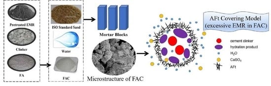
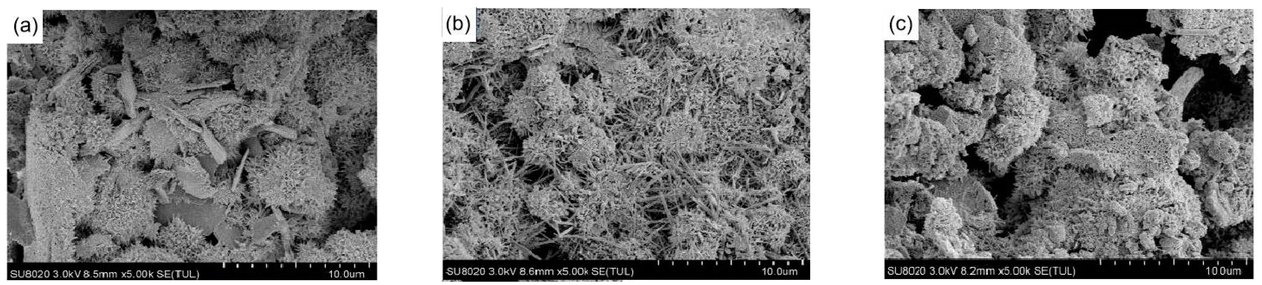
3.3. Effect of Electrolytic Manganese Residue on Microstructure of FAC

The SEM images of hydration products of three samples (FAC1, FAC2, and FAC3) hydrated at 28 days are shown in Figure 6. The amorphous gel can be seen covering the paste matrix, which is dotted with thin rod-shaped AFt and flake Ca(OH)2 [31,32]. The main components of amorphous gel are C-S-H gel and C-A-S-H gel. The surface of the unreacted particle is covered with fiber gels. It can be seen from Figure 6a that the surface of the FAC1 paste matrix is covered with flocculent material on which the needle-bar ettringite grows. However, the amount of ettringite is relatively less with sparse distribution, and flakier Ca(OH)2 is also on the surface. Previous studies have shown that excessive Ca(OH)2 dosage in hardened cement paste will lead to lower strength, while high content of gels will improve mechanical properties [33,34]. Figure 6b shows that the content of AFt increases significantly with serried distribution, and the spatial structure is compact, so the strength of FAC2 is higher than that of FAC1. Meanwhile, few Ca(OH)2 can be found in FAC2 paste. The reason is that more Ca(OH)2 is consumed by the pozzolanic reaction of fly ash, which leads to formation of more hydration products. With the increases of gelatinous products, the hydration products are interwoven into a network structure, making the structure more compact. It can be seen from Figure 6c that large pores appear on the matrix surface of FAC3. The amorphous gels are smaller than those in Figure 6a. It proves that the cementitious substances in FAC3 are small, and the filling of gaps between the matrix is insufficient, resulting in a looser structure and lower strength. This conforms to the results of the XRD analysis.
As can be seen from Figure 6c, there are some particles and gels coated with AFt. It is known that the clinker reacts with water to form hydration products, such as tricalcium aluminate hydrate, C-S-H gel, etc. The sulfate in EMR contacts the hydration products and reacts with the fly ash to form AFt. If the sulfate content is not much, such as the FAC1 sample, the pozzolanic property of fly ash is not sufficiently activated, resulting in a low initial formation rate of AFt, which incompletely covers the surface of particles and gel. Water and sulfate salts react seamlessly with clinker and fly ash to form ettringite [12,28,35]. In other words, ettringite continues to grow. Once an excess of sulfate is added, such as FAC3 sample, much AFt is produced initially on the clinker surface, which grows and coats clinker particles and gels. Figure 7 presents an AFt covering a model in case of excess sulfate provided by EMR in the hydrated FAC3 paste. As shown in Figure 7, the dense AFt film may prevent sulfate and water from contacting the granule and prematurely terminate the formation of AFt. The volume expansion process of FAC3 is interrupted, resulting in particles less than 15 μm shown in Figure 6c. These particles may have less connection area with the matrix or even be separate from the matrix. Therefore, excessive sulfate provided by EMR is not conducive to the growth of AFt, affecting the development of strength. Cement particles clump together to form large and irregularly shaped particles. As the AFt crystal grows larger and larger, it continues to encroach on the surrounding space, resulting in expansion stress [36,37,38,39,40]. Once the expansion stress is greater than the tensile strength of AFt, the AFt film will be broken, forming fine cracks.
It is generally believed that pore structure and porosity strongly influence the mechanical properties and transport properties of cement paste [37]. The mercury intrusion test obtained the representative parameters of pore structure for three samples (FAC1, FAC2, and FAC3), and the results are shown in Table 3. It can be seen that the porosity, total pore volume, and average pore diameter of FAC2 paste are the lowest, indicating that the pore structure of the FAC2 sample is the most compact. We found that the bulk density and apparent density increased first and then decreased by comparing the three samples. Hence, more hydraulic cementitious substances are generated in the FAC2 sample [38] because the density of C-S-H gel is higher compared with other hydration products, leading to higher mechanical properties [39]. Meanwhile, it also proves that although the addition of EMR can introduce some inert substances, the optimum content of EMR can effectively improve the mechanical properties of FAC.
Critical pore diameter refers to the maximum pore level that can connect large pores, reflecting pore connectivity and permeability paths’ tortuosity [40,41]. Moreover, the critical pore diameter has the most important effect on the permeability of hardened cement paste. Figure 8 presents the cumulative porosity curves and log-differential volume curves of three samples hydrated at 28 days. The value of critical pore diameter can be obtained from the inflection point by analyzing the slope of the cumulative porosity curve in Figure 8a, and the corresponding value is 21.1, 9.1, and 22.0 nm, respectively. The smallest value of critical pore diameter is obtained by FAC2, which indicates that its pore structure is the finest [28]. Low sulfate content in FAC1 leads to the insufficient formation of AFt, which leads to a higher value of critical pore diameter than FAC2. The highest value of critical pore diameter for FAC3 is related to the cracks caused by volume expansion resulting from the excessive sulfate in FAC3. Therefore, proper EMR content can obtain a medium pore gradation, making the pore size smaller and reducing the permeability of FAC paste.
As can be seen from Figure 8b, the area surrounded by a differential curve and transverse axis represents total pore volume. The aperture corresponding to the peak value of the curve is the threshold pore diameter within a certain pore size range. It represents the pore size with the highest probability of occurrence [28,42]. Its physical meaning is that no connected pore can be formed in hardened paste when the pore size is smaller than that. It can be seen from Figure 8b that there is a gap between the total pore volume and porosity, proving that similar hydration products have been produced. Meanwhile, the threshold aperture of the FAC2 sample is the smallest, and the threshold aperture of the FAC3 sample is much higher than that of FAC1 and FAC2. It shows that the pore structure connectivity of FAC2 is weaker, resulting in lower permeability.
Table 4 shows the pore size distribution of three samples hydrated at 28 days. Previous studies show that gel pore size is less than 10 nm, the meso-capillary pore size is from 10 nm to 50 nm, and the macro-capillary pore size is more than 50 nm [43]. Among them, the macro-capillary pore is harmful to the development of strength. It can be seen from Table 4 that the porosity decreases for FAC2 when the content of EMR is 10%. Meanwhile, the content of the meso-capillary pore and macro-capillary pore decreases, the content of gel pore increases, which has a good effect on improving the macroscopic properties of FAC2, such as reducing shrinkage [44]. Many macro-capillary pores appear in FAC1 and FAC3 samples, indicating that the pore is rough and not conducive to producing a favorable void structure. FAC3 has more large pores than FAC1, mainly due to volume expansion and cracking caused by excessive sulfate, confirming the previous hypothesis. The result declares that the pores are well filled, and the pore size is small with the hydration of the FAC2 sample. In summary, the pore structure of the FAC2 sample was the best, and the strength was the highest when the EMR dosage was 10%.
29Si nuclear magnetic resonance (NMR) technology is often used to research the interaction around Si nuclei. As a powerful analytical tool, NMR technology has been widely used in the field of cement [45]. The chemical environment of 29Si is expressed by Qn in silicates. Table 5 expresses the scope of the chemical shift of SiQn in 29Si NMR spectra. Qn means that there are n silicon-oxygen tetrahedrons associated with [SiO4]. For example, Q0 means a single silicon-oxygen tetrahedron, Q4 represents a framework silicate structure [46,47]. In addition to the nearest atom coordination, the next-nearest atom effect also greatly influences the chemical shift. The chemical shift moves in a positive direction when the next approaching atom is an aluminum atom. Qn (mAl) represents [AlO4] connected to [SiO4]. The letter “m” denotes the number of aluminum-oxygen tetrahedrons connected to the central silicon-oxygen tetrahedron. Zhang et al. [48] thought the relative number of bridging oxygen (RBO) could be calculated as follows:
RBO = 1 4 ( 1 × Q 1 Σ Q n + 2 × Q 2 Σ Q n + 3 × Q 3 Σ Q n + 4 × Q 4 Σ Q n ) = 1 4 × Σ n · Q n Σ Q n
Qn means the area of the corresponding formant.
It is necessary to determine the location and attribution of the resonance peak to accurately calculate the area. The superimposed formant was divided into several peaks, then the relative area was calculated, which could characterize the polymerization degree of [SiO4] to some extent.
Figure 9 shows the 29Si NMR spectra of three paste samples (FAC1, FAC2, and FAC3) hydrated at 28 days. The peak position, assign, relative area, and RBO value of the three samples are shown in Table 6. Q0 represents the tricalcium silicate and part of dicalcium silicate, which were unhydrated. Q1 corresponds to silicon-oxygen tetrahedron at the two ends of chain C-S-H gel. Q2 represents silicon-oxygen tetrahedron in the middle part of chain C-S-H gel. The assign like Qn (mAl) is because of the production of C-A-S-H gel. A part of aluminum replaces the position of silicon in the reaction process. It can be seen from Figure 9 that all three samples have five resonance peaks in the spectra. They correspond to SiQ0, SiQ1, SiQ2(1Al), SiQ2, and SiQ3, respectively. The Q0 formant of the FAC2 sample is the lowest, which indicates that the hydration of clinker is more sufficient to produce more cementitious substances. Once again, it demonstrates that appropriate sulfate can stimulate the pozzolanic activity of fly ash and promote the growth of AFt, while the sulfate content exceeding a specific range will hinder the hydration process of clinker. The RBO of the FAC2 sample presents the maximum value, indicating that the [SiO4] tetrahedron of the FAC2 sample has the best polymerization degree, and resulting in the highest strength [49].

3.4. Effect of Electrolytic Manganese Residue on Environmental Performance of FAC

Ammonia nitrogen (NH3-N) and heavy metals in EMR should not be ignored. In this experiment, the FAC made from EMR should meet the environmental performance evaluation index. The leaching test of EMR and FAC mortar specimens was carried out according to Chinese standard HJ/T 300-2007. Firstly, EMR and the FAC mortar specimens were immersed in PTFE bottles containing acidic buffer solution at a 1:20 solid-liquid ratio and then extracted in a rotatory machine spinning at a speed of 30 ± 2 rotations/min for 18 h. Thereafter, the percolate was analyzed by using ICP. Then, the leaching test results were compared with the national integrated sewage discharge standard GB 8978-1996, as shown in Table 7. Because the content of NH3-N and heavy metals in the raw EMR exceeds the standard, untreated EMR is not allowed to be directly discharged back to nature. The NH3-N in EMR can be effectively removed based on OH-. The heavy metal ions of EMR could be adsorbed in AFt and gels in the hydrated FAC paste [50]. The leaching test result shows that the prepared FAC has good environmental performance, and using proper content of EMR to prepare FAC is safe for the environment.

4. Conclusions

EMR can be used for the preparation of fly ash-based cementitious material due to the gypsum composed in EMR. The compressive strength of FAC mortar at 28 days can reach 50 MPa when the optimal content of EMR is 10%. Insufficient sulfate from EMR cannot adequately stimulate the pozzolanic activity of fly ash, while excessive content of sulfate from EMR hinders the hydration of clinker, both of which are not conducive to the early strength development of FAC. Excess sulfate from EMR will even cause cracking of FAC sample in the later stage and finally affect the strength growth.
The main hydration products of FAC are AFt, Ca(OH)2, C-S-H gel, C-A-S-H gel, and CaAl2Si4O12·4H2O. The content of AFt and gels is the highest in the FAC2 sample. At the same time, more Ca(OH)2 is consumed by the pozzolanic reaction of fly ash to promote the strength development of FAC2.
The highest RBO value of 32.60% is obtained by the FAC2 sample, indicative of the best [SiO4] polymerization structure. The lowest values of critical pore diameter can also be obtained by the FAC2 sample. Moreover, the pores in the FAC2 sample tend to be harmless, causing a more compact pore structure.
Leaching experiments show that Mn, Cr, Cd, As, and Pb ions in EMR could be significantly adsorbed in AFt and gels, and the NH3-N in EMR is effectively removed from the FAC. Thus, FAC shows good environmental performance.

Supplementary Materials

The following are available online at https://www.mdpi.com/article/10.3390/ma14227047/s1, Figure S1: XRD pattern of calcium carbide slag, Figure S2: XRD pattern of fly ash.

Author Contributions

Conceptualization, N.Z. and X.L.; methodology, X.L.; software, Y.W. and Y.R.; validation, Y.X., Y.R. and N.Z.; formal analysis, Y.W.; investigation, Y.W.; resources, N.Z. and X.L.; data curation, Y.X.; writing—original draft preparation, Y.X. and Y.R.; writing—review and editing, Y.W.; visualization, N.Z.; supervision, X.L.; project administration, N.Z. and X.L.; funding acquisition, N.Z. and X.L. All authors have read and agreed to the published version of the manuscript.

Funding

This research was funded by the National Natural Science Foundation of China, project number 52074035 and 51974283, Fundamental Research Funds for the Central Universities, project number 2652019034, and National Key Research and Development Program of China, project number 2020YFC1910000.

Institutional Review Board Statement

Not applicable.

Informed Consent Statement

Not applicable.

Data Availability Statement

Data sharing is not applicable to this article.

Conflicts of Interest

The authors declare no conflict of interest.

References

  1. Hagelstein, K. Globally sustainable manganese metal production and use. J. Environ. Manag. 2009, 90, 3736–3740. [Google Scholar] [CrossRef] [PubMed]
  2. Duan, N.; Wamg, F.; Zhou, C.; Zhu, C.; Yu, H. Analysis of pollution materials generated from electrolytic manganese industries in China. Resour. Conserv. Recycl. 2010, 54, 506–511. [Google Scholar] [CrossRef]
  3. Shu, J.; Liu, R.; Liu, Z.; Du, J.; Tao, C. Electrokinetic remediation of manganese and ammonia nitrogen from electrolytic manganese residue. Environ. Sci. Pollut. Res. 2015, 22, 16004–16013. [Google Scholar] [CrossRef] [PubMed]
  4. Chen, H.; Liu, R.; Shu, J.; Li, W. Simultaneous stripping recovery of ammonia-nitrogen and precipitation of manganese from electrolytic manganese residue by air under calcium oxide assist. J. Environ. Sci. Health Part. A Toxic Hazard. Subst. Environ. Eng. 2015, 50, 1282–1290. [Google Scholar] [CrossRef] [PubMed]
  5. Li, C.; Zhong, H.; Wang, S.; Xue, J.; Zhang, Z. A novel conversion process for waste residue: Synthesis of zeolite from electrolytic manganese residue and its application to the removal of heavy metals. Colloids Surf. A 2015, 470, 258–267. [Google Scholar] [CrossRef]
  6. Feng, Y.; Zhang, S.; Li, H. Reductive leaching of manganese from low-grade pyrolusite ore in sulfuric acid using pyrolysis-pretreated sawdust as a reductant. Int. J. Miner. Metall. Mater. 2016, 23, 241–246. [Google Scholar] [CrossRef]
  7. Li, C.; Zhong, H.; Wang, S.; Xue, J. Leaching Behavior and risk assessment of heavy metals in a landfill of electrolytic manganese residue in western Hunan, China. Hum. Ecol. Risk Assess. 2014, 20, 1249–1263. [Google Scholar] [CrossRef]
  8. Duan, N.; Dan, Z.; Wang, F.; Pan, C.; Zhou, C.; Jiang, L. Electrolytic manganese metal industry experience based China’s new model for cleaner production promotion. J. Clean. Prod. 2011, 19, 2082–2087. [Google Scholar] [CrossRef]
  9. Zhou, C.; Wang, J.; Wang, N. Treating electrolytic manganese residue with alkaline additives for stabilizing manganese and removing ammonia. Korean J. Chem. Eng. 2013, 30, 2037–2042. [Google Scholar] [CrossRef]
  10. Wang, Z.; Sun, J.; Qian, J.; Hou, P.; Cao, J. Study on sulfate of electrolytic manganese residue. Mater. Rev. 2010, 24, 61–64. [Google Scholar]
  11. Li, T.; Xie, H.; He, X.; Zhou, X. Experimental study of calcined electrolysis manganese residue and fly ash complex admixture. Bull. Chin. Ceram. Soc. 2007, 26, 567–571. [Google Scholar]
  12. Hou, P.; Qian, J.; Wang, Z.; Deng, C. Production of quasi-sulphoaluminate cementitious materials with electrolytic manganese residue. Cem. Concr. Compos. 2011, 34, 248–254. [Google Scholar] [CrossRef]
  13. Yang, C.; Lv, X.; Tian, X.; Wang, Y.; Komarneni, S. An investigation on the use of electrolytic manganese residue as filler in sulfur concrete. Constr. Build. Mater. 2014, 73, 305–310. [Google Scholar] [CrossRef]
  14. Li, C.; Zhong, H.; Wang, S.; Xue, J.; Wu, F.; Zhang, Z. Preparation of MnO2 and calcium silicate hydrate from electrolytic manganese residue and evaluation of adsorption properties. J. Cent. South. Univ. 2015, 22, 2493–2502. [Google Scholar] [CrossRef]
  15. Du, B.; Zhou, C.; Dan, Z.; Luan, Z.; Duan, N. Preparation and characteristics of steam-autoclaved bricks produced from electrolytic manganese solid waste. Constr. Build. Mater. 2014, 50, 291–299. [Google Scholar] [CrossRef]
  16. Jiang, X.; Wang, Z.; Hou, P.; Qian, J.; Cao, J. Experimental Study on Preparation of Non-burnt Brick from Electrolytic Manganese Residue. Non-Met. Mines. 2010, 33, 2008–2011. [Google Scholar]
  17. Phoo-ngernkham, T.; Chindaprasirt, P.; Sata, V.; Pangdaeng, S.; Sinsiri, T. Properties of high calcium fly ash geopolymer pastes with Portland cement as an additive. Int. J. Miner. Metall. Mater. 2013, 20, 214–220. [Google Scholar] [CrossRef]
  18. Zhu, J.; Yan, H. Microstructure and properties of mullite-based porous ceramics produced from coal fly ash with added Al2O3. Int. J. Miner. Metall. Mater. 2017, 24, 309–315. [Google Scholar] [CrossRef]
  19. Ahmaruzzaman, M. A review on the utilization of fly ash. Prog. Energy Combust. Sci. 2010, 36, 327–363. [Google Scholar] [CrossRef]
  20. Xu, Y.; Yang, B.; Liu, X.; Gao, S.; Li, D.; Mukiza, E.; Li, H. Investigation of the medium calcium based non-burnt brick made by red mud and fly ash: Durability and hydration characteristics. Int. J. Miner. Metall. Mater. 2019, 26, 983–991. [Google Scholar] [CrossRef]
  21. Gu, K.; Chen, B. Research on the incorporation of untreated flue gas desulfurization gypsum into magnesium oxysulfate cement. J. Clean. Prod. 2020, 271, 122497. [Google Scholar] [CrossRef]
  22. Demir, İ.; Güzelkücük, S.; Sevim, Ö. Effects of sulfate on cement mortar with hybrid pozzolan substitution. Eng. Sci. Technol. 2018, 21, 275–283. [Google Scholar] [CrossRef]
  23. Liu, S.; Liu, W.; Jiao, F.; Qin, W.; Yang, C. Production and resource utilization of flue gas desulfurized gypsum in China—A review. Environ. Pollut. 2021, 288, 117799. [Google Scholar] [CrossRef]
  24. Xu, Y.; Liu, X.; Zhang, Y.; Tang, B.; Mukiza, E. Investigation on sulfate activation of electrolytic manganese residue on early activity of blast furnace slag in cement-based cementitious material. Constr. Build. Mater. 2019, 229, 116831. [Google Scholar] [CrossRef]
  25. Li, Z.; Zhang, J.; Li, S.; Gao, Y.; Liu, C.; Qi, Y. Effect of different gypsums on the workability and mechanical properties of red mud-slag based grouting materials. J. Clean. Prod. 2020, 245, 118759. [Google Scholar] [CrossRef]
  26. Wang, Z.; Guo, Q.; Jiang, X.; Hou, P.; Qian, J. Sulphate Activating of Electrolytic Manganese Residue to Fly Ash. Non-Met. Mines. 2011, 34, 5–8. [Google Scholar]
  27. Wang, Q.; Yang, J.; Chen, H. Long-term properties of concrete containing limestone powder. Mater. Struct. 2017, 50, 168. [Google Scholar] [CrossRef]
  28. Zhang, Y.; Liu, X.; Xu, Y.; Tang, B.; Wang, Y.; Mukiza, E. Preparation and characterization of cement treated road base material utilizing electrolytic manganese residue. J. Clean. Prod. 2019, 232, 980–992. [Google Scholar] [CrossRef]
  29. Maciel, M.; Soares, G.; Romano, R.; Cincotto, M. Monitoring of Portland cement chemical reaction and quantification of the hydrated products by XRD and TG in function of the stoppage hydration technique. J. Therm. Anal. Calorim. 2019, 136, 1269–1284. [Google Scholar] [CrossRef]
  30. He, T.; Gao, Z.; Li, S.; Zhao, S.; Bao, C. Influence of Gypsum Dosage on Performances of Silicate Mixed by Slag. Bull. Chin. Ceram. Soc. 2012, 31, 521–525. [Google Scholar]
  31. Ylmén, R.; Jäglid, U.; Steenari, B.; Panas, I. Early hydration and setting of Portland cement monitored by IR, SEM and Vicat techniques. Cem. Concr. Res. 2009, 39, 433–439. [Google Scholar] [CrossRef]
  32. Chen, J.; Sorelli, L.; Vandamme, M.; Ulm, F.; Chanvillard, G. A coupled nanoindentation/SEM-EDS study on low water/cement ratio portland cement paste: Evidence for C-S-H/Ca(OH)2 nanocomposites. J. Am. Ceram. Soc. 2010, 93, 1484–1493. [Google Scholar] [CrossRef] [Green Version]
  33. Feng, J.; Cheng, L.; Zhou, X.; Xu, H.; Weir, M.; Li, Q.; Hannig, M.; Rupf, S. Effects of water aging on the mechanical and anti-biofilm properties of glass-ionomer cement containing dimethylaminododecyl methacrylate. Dent. Mater. 2019, 35, 434–443. [Google Scholar] [CrossRef] [PubMed]
  34. Wang, Q.; Wang, D.; Zhuang, S. The soundness of steel slag with different free CaO and MgO contents. Constr. Build. Mater. 2017, 151, 138–146. [Google Scholar] [CrossRef]
  35. Zhang, J.; Zhang, N.; Li, C.; Zhang, Y. Strength development mechanism of a marine binding material with red mud and seawater. Constr. Build. Mater. 2021, 303, 124428. [Google Scholar] [CrossRef]
  36. Pavoine, A.; Brunetaud, X.; Divet, L. The impact of cement parameters on Delayed Ettringite Formation. Cem. Concr. Compos. 2012, 34, 521–528. [Google Scholar] [CrossRef]
  37. Gu, Y.; Martin, R.; Metalssi, O.; Fen-Chong, T.; Dangla, P. Pore size analyses of cement paste exposed to external sulfate attack and delayed ettringite formation. Cem. Concr. Res. 2019, 123, 105766. [Google Scholar] [CrossRef]
  38. Yu, J.; Qian, J.; Tang, J.; Ji, Z.; Fan, Y. Effect of ettringite seed crystals on the properties of calcium sulphoaluminate cement. Constr. Build. Mater. 2019, 207, 249–257. [Google Scholar] [CrossRef]
  39. Qoku, E.; Bier, T.; Westphal, T. Phase assemblage in ettringite-forming cement pastes: A X-ray diffraction and thermal analysis characterization. J. Build. Eng. 2017, 12, 37–50. [Google Scholar] [CrossRef]
  40. Leklou, N.; Nguyen, V.; Mounanga, P. The effect of the partial cement substitution with fly ash on Delayed Ettringite Formation in heat-cured mortars. KSCE J. Civ. Eng. 2017, 21, 1359–1366. [Google Scholar] [CrossRef]
  41. Sinsiri, T.; Chindaprasirt, P.; Jaturapitakkul, C. Influence of fly ash fineness and shape on the porosity and permeability of blended cement pastes. Int. J. Miner. Metall. Mater. 2010, 17, 683–690. [Google Scholar] [CrossRef]
  42. Hanif, A.; Parthasarathy, P.; Ma, H.; Fan, T.; Li, Z. Properties improvement of fly ash cenosphere modified cement pastes using nano silica. Cem. Concr. Compos. 2017, 81, 35–48. [Google Scholar] [CrossRef]
  43. Wang, Q.; Wang, D.; Chen, H. The role of fly ash microsphere in the microstructure and macroscopic properties of high-strength concrete. Cem. Concr. Compos. 2017, 83, 125–137. [Google Scholar] [CrossRef]
  44. Ma, H. Mercury intrusion porosimetry in concrete technology: Tips in measurement, pore structure parameter acquisition and application. J. Porous Mater. 2014, 21, 207–215. [Google Scholar] [CrossRef]
  45. Diamond, S. Mercury porosimetry: An inappropriate method for the measurement of pore size distributions in cement-based materials. Cem. Concr. Res. 2000, 30, 1517–1525. [Google Scholar] [CrossRef]
  46. Liu, X.; Zhang, N.; Yao, Y.; Sun, H.; Feng, H. Micro-structural characterization of the hydration products of bauxite-calcination-method red mud-coal gangue based cementitious materials. J. Hazard. Mater. 2013, 262, 428–438. [Google Scholar] [CrossRef] [PubMed]
  47. Zhang, N.; Liu, X.; Sun, H. Hydration Characteristics of Intermediate-Calcium Based Cementitious Materials from Red Mud and Coal Gangue. Chin. J. Mater. Res. 2014, 28, 325–332. [Google Scholar]
  48. Zhang, J.; Sun, H.; Wang, J.; Zhang, N. 29Si polymerization degree of hydrates in coal gangue added cement. J. Cent. South. Univ. (Sci. Technol.) 2011, 42, 329–335. [Google Scholar]
  49. Snoeck, D.; Pel, L.; De Belie, N. Superabsorbent polymers to mitigate plastic drying shrinkage in a cement paste as studied by NMR. Cem. Concr. Compos. 2018, 93, 54–62. [Google Scholar] [CrossRef]
  50. Peng, D.; Wang, Y.; Liu, X.; Tang, B.; Zhang, N. Preparation, characterization, and application of an eco-friendly sand-fixing material largely utilizing coal-based solid waste. J. Hazard. Mater. 2019, 373, 294–302. [Google Scholar] [CrossRef] [PubMed]
Figure 1. The particle size distribution of raw materials: (a) EMR, (b) fly ash, and (c) clinker.
Materials 14 07047 g001
Figure 2. Preparation process of FAC and mortar blocks.
Materials 14 07047 g002
Figure 3. Strength of FAC mortars at different ages: (a) flexural strength and (b) compressive strength.
Materials 14 07047 g003
Figure 4. XRD patterns of FAC hydrated pastes at 28 days.
Materials 14 07047 g004
Figure 5. TG-DTG curves of FAC paste samples at 28 days: (a) FAC1, (b) FAC2, and (c) FAC3.
Materials 14 07047 g005
Figure 6. SEM images of hydration products of FAC samples at 28d: (a) FAC1, (b) FAC2, and (c) FAC3.
Materials 14 07047 g006
Figure 7. AFt covering model in the case of excessive EMR composed in the FAC.
Materials 14 07047 g007
Figure 8. Cumulative porosity curves (a) and log-differential volume curves (b) of FAC samples hydrated at 28 days.
Materials 14 07047 g008
Figure 9. 29Si NMR spectra of three samples hydrated at 28 days: (a) FAC1, (b) FAC2, and (c) FAC3.
Materials 14 07047 g009
Table 1. Chemical composition of raw materials (%).
OxidesSiO2Al2O3Fe2O3CaOMgOMnOSO3LOI
EMR29.638.325.4114.821.792.0229.548.47
FA47.3837.098.023.120.340.051.352.63
Clinker18.63.813.2564.852.890.340.434.14
Table 2. Proportions of FAC samples (wt%).
SamplesClinkerEMRFASO3Fineness (m2/kg)
FAC0550450.8377
FAC1555402.3380
FAC25510353.1385
FAC35515304.2376
FAC45520255.4373
Table 3. The representative parameters of pore structure of FAC paste hydrated at 28 days.
SamplesBET
(m2/g)
Total Pore Volume
(mg/L)
Average Pore Diameter
(nm)
Porosity
(%)
Bulk Density
(g/cm3)
Apparent Density
(g/cm3)
FAC1231.000.3117.640.321.302.22
FAC2230.000.2915.839.441.342.24
FAC3232.000.3218.441.761.302.19
Table 4. Pore size distribution of FAC samples hydrated at 28 days.
SamplesPorosity (%)Pore Size Distribution (%)
<10 nm10–50 nm>50 nm
FAC140.327.9116.1716.24
FAC239.449.7815.1114.55
FAC341.769.1513.9518.66
Table 5. 29Si NMR chemical shift of SiQn in solid silicates.
SymbolSiQ0SiQ1SiQ2SiQ3SiQ4
Chemical shift (ppm)−68–−76−76–−82−82–−88−88–−98−98–−129
Table 6. The RBO values of FAC samples hydrated at 28 days.
SamplesPeak Position (ppm)AssignRelativeRBO Value
FAC1−71.29SiQ023.8330.99%
−79.63SiQ1100
−84.80SiQ2(1Al)22.27
−85.15SiQ241.80
−93.81SiQ32.73
FAC2−71.45SiQ016.3132.60%
−81.37SiQ1100
−83.97SiQ2(1Al)29.08
−87.00SiQ234.75
−94.84SiQ34.26
FAC3−71.54SiQ035.0229.58%
−79.42SiQ1100
−84.29SiQ2(1Al)22.96
−85.34SiQ231.13
−90.91SiQ38.56
Table 7. Results of leaching tests (mg/L).
SamplesMnCrCdAsPbNH3-N
EMR11680.2050.0640.1580.29324.53
FAC1<0.001<0.001<0.001<0.0010.0010.26
FAC2<0.0010.001<0.001<0.0010.0030.35
FAC3<0.0010.002<0.001<0.0010.0050.52
GB/T 8978-19962.01.50.10.51.015
Publisher’s Note: MDPI stays neutral with regard to jurisdictional claims in published maps and institutional affiliations.

