
Microstructure and Mechanical Properties of Friction Stir Welded 2205 Duplex Stainless Steel Butt Joints

 ,
, 
 ,
,  ,
, 
Abstract
:1. Introduction
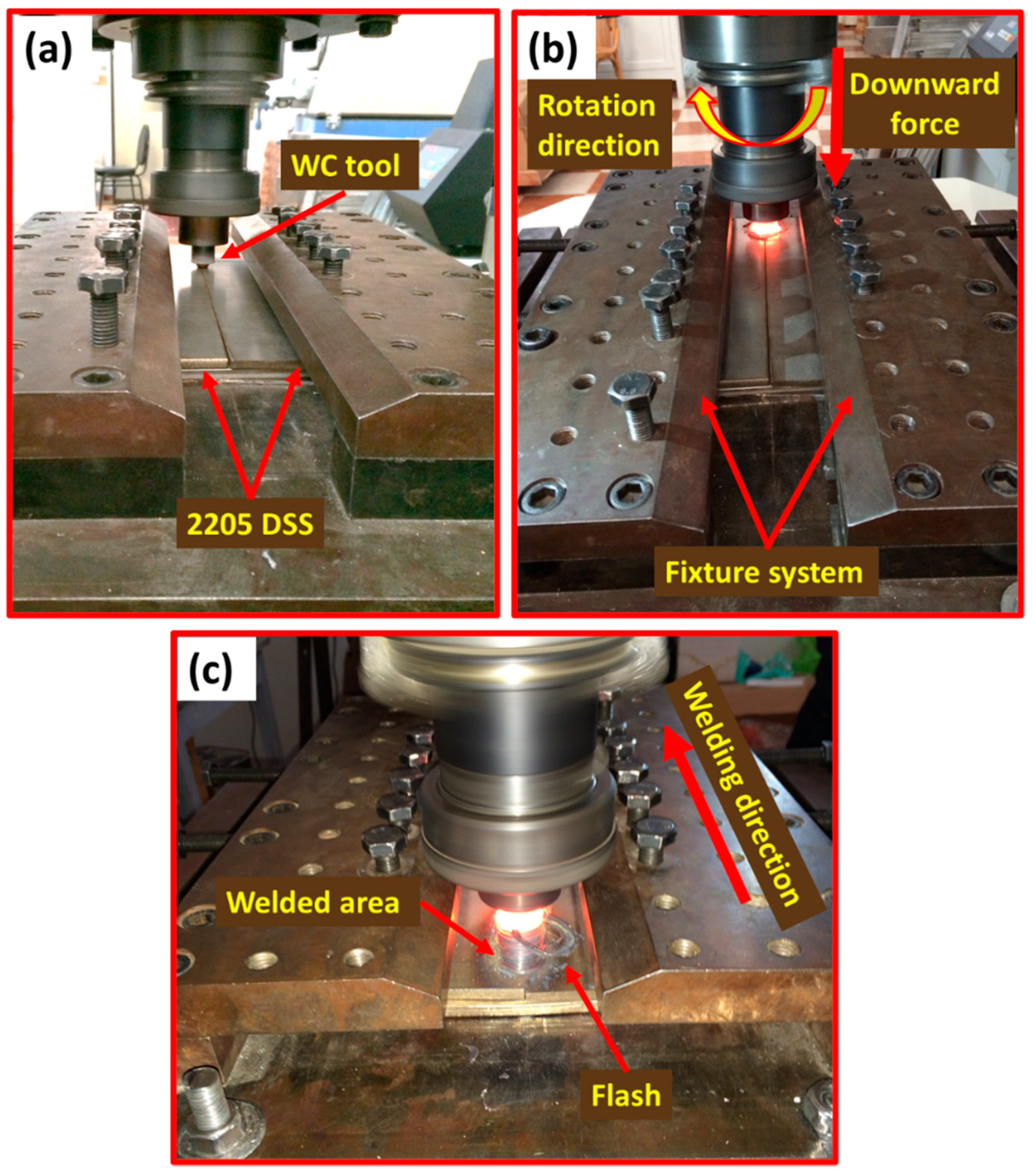
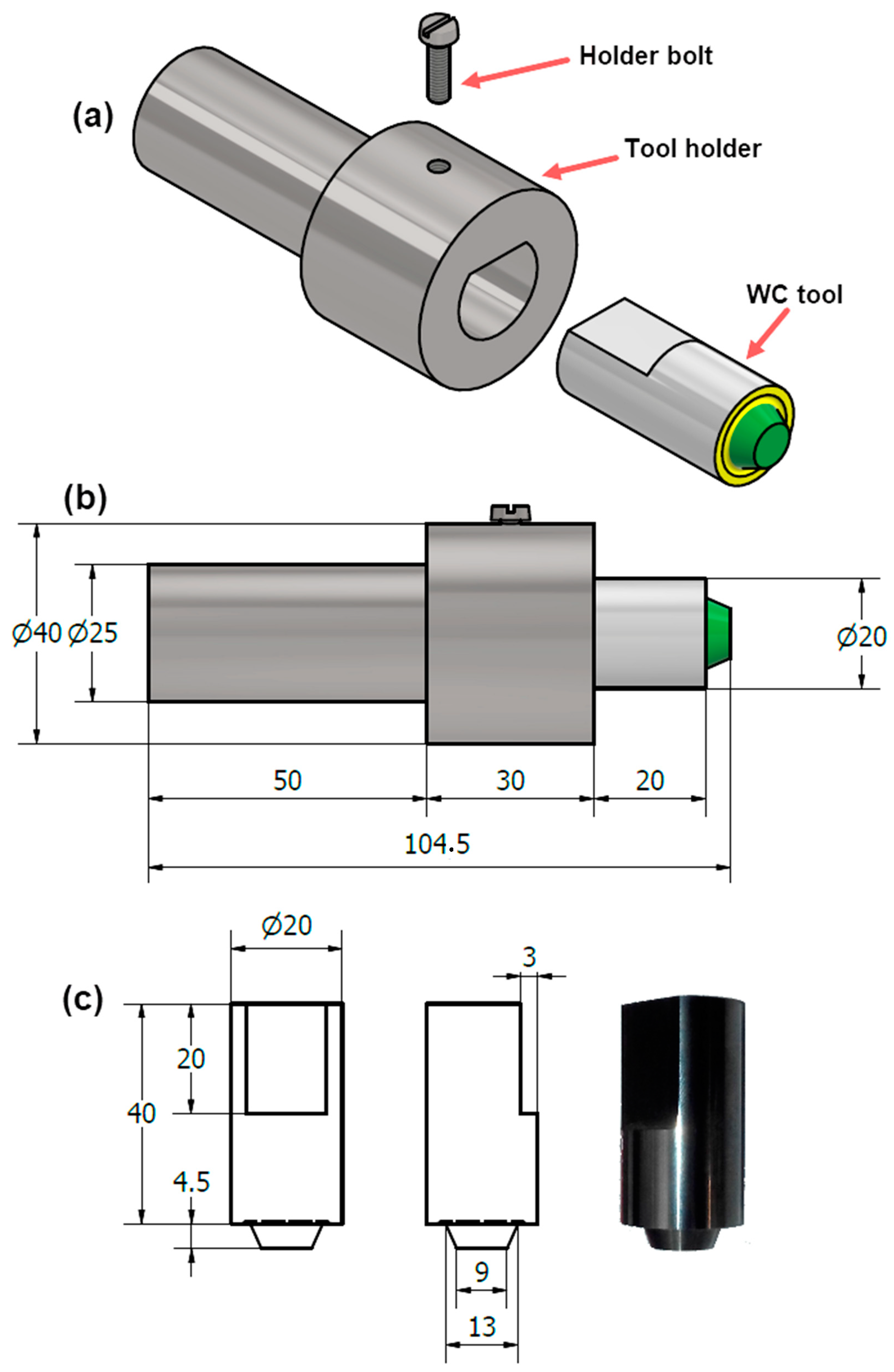
2. Methodology
3. Results and Discussion
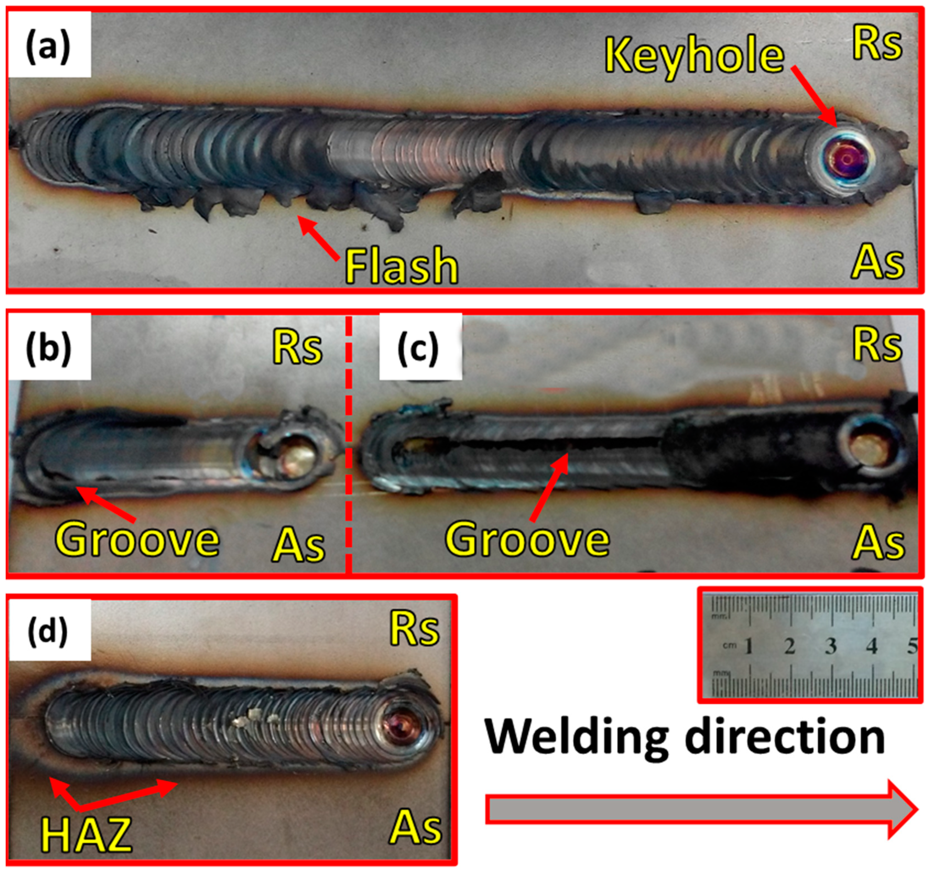
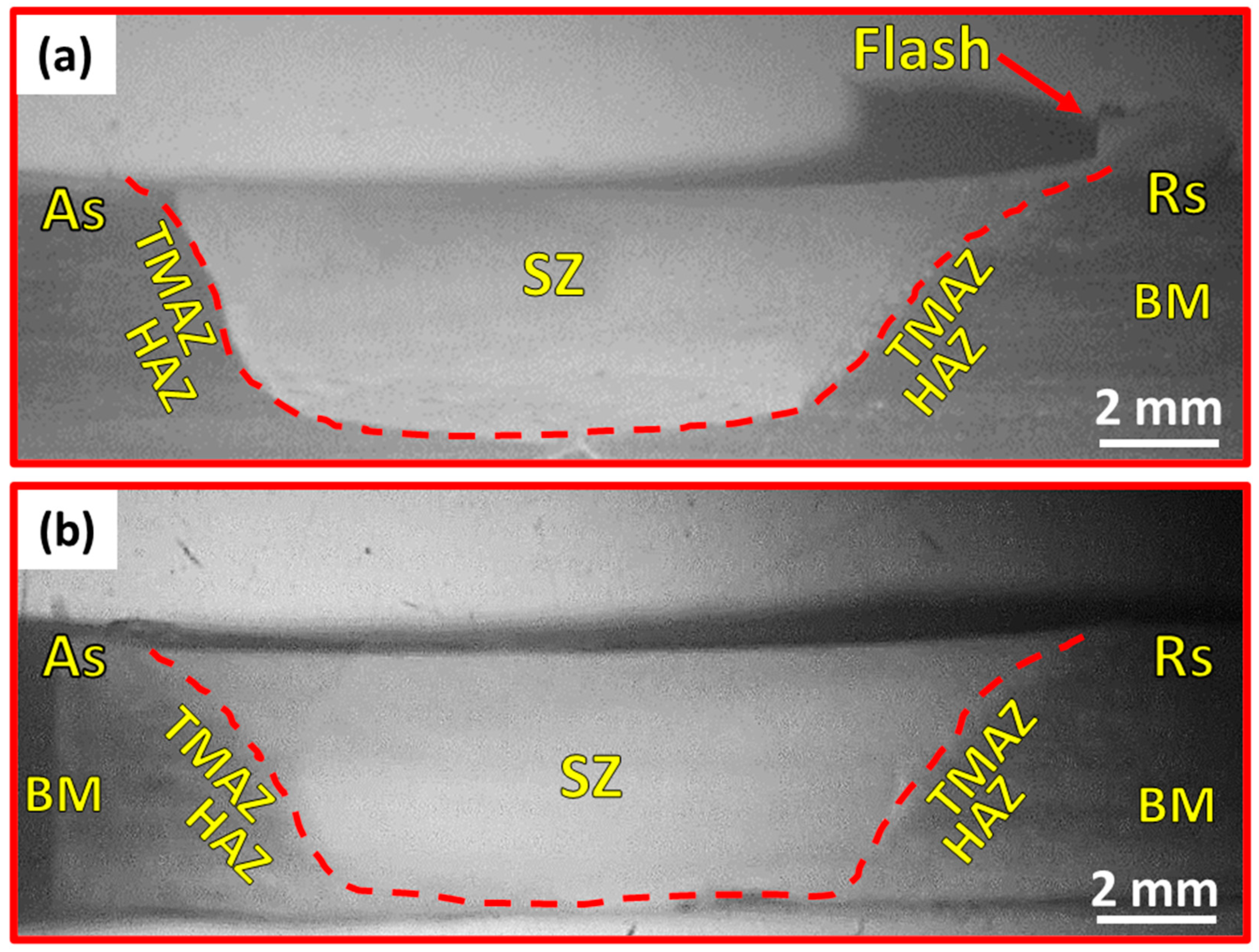
3.1. Visual and Macrostructure Examination
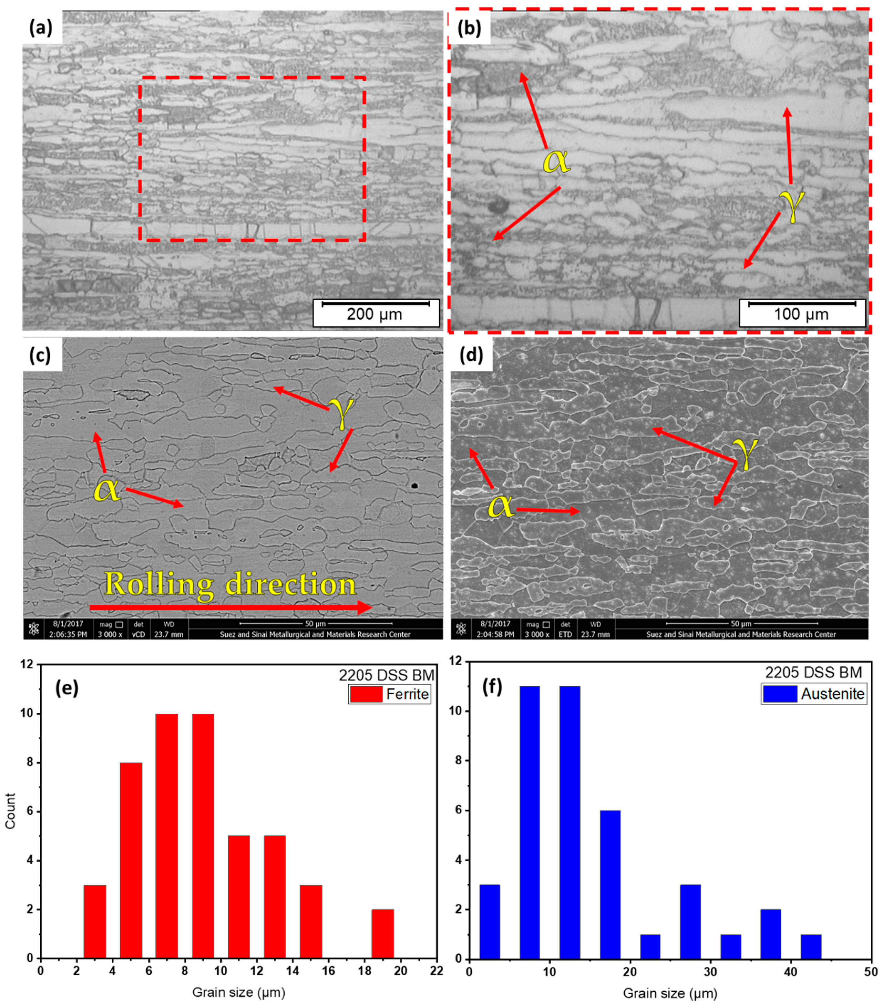
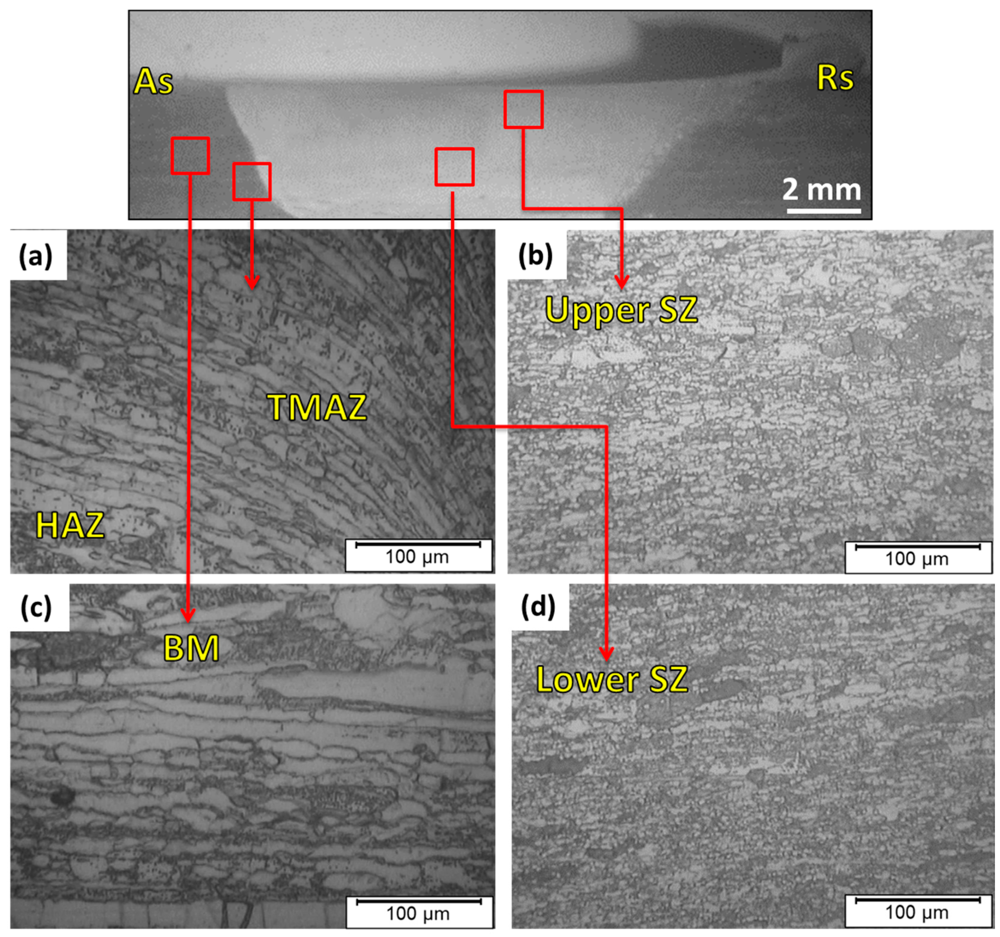
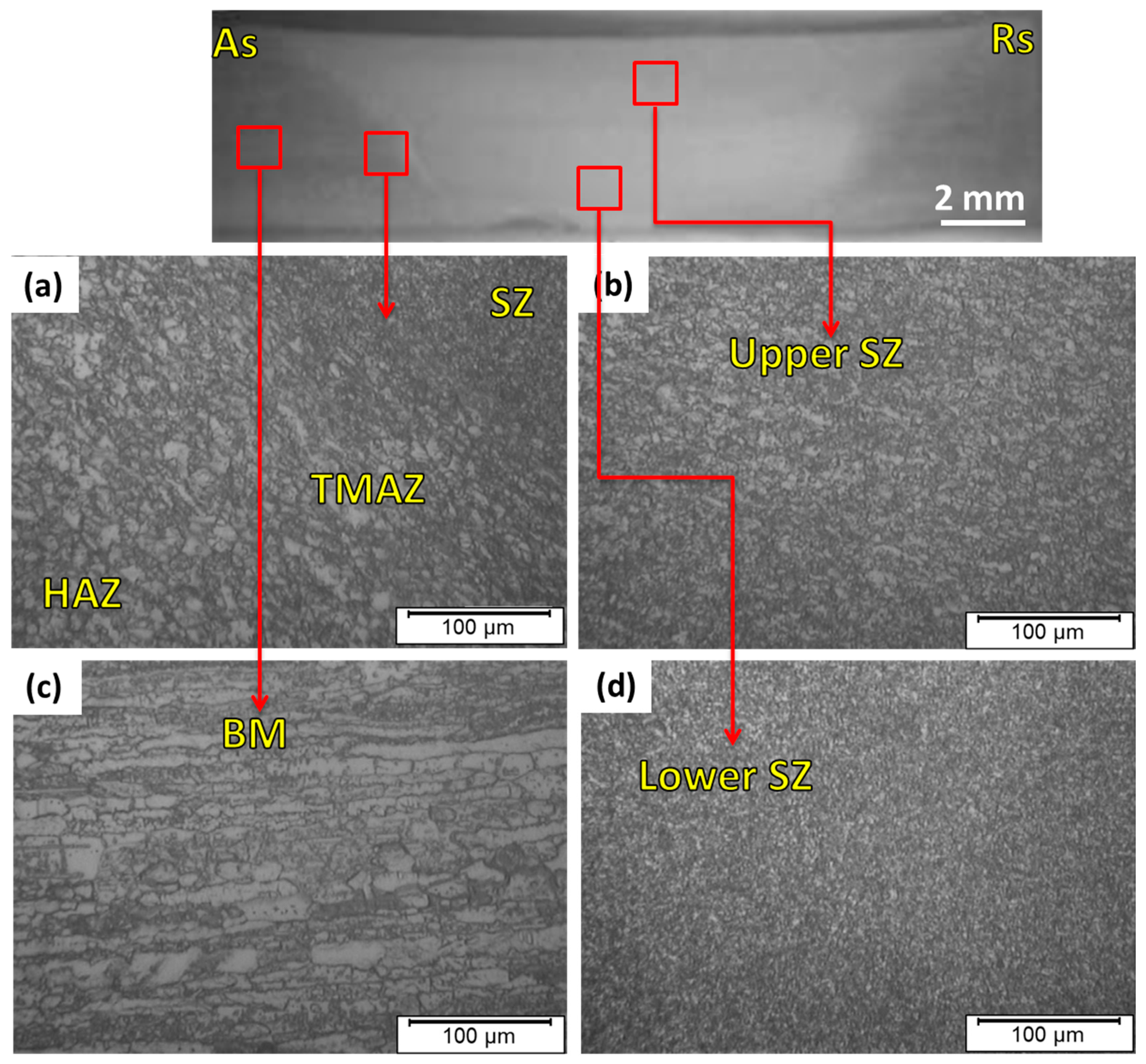
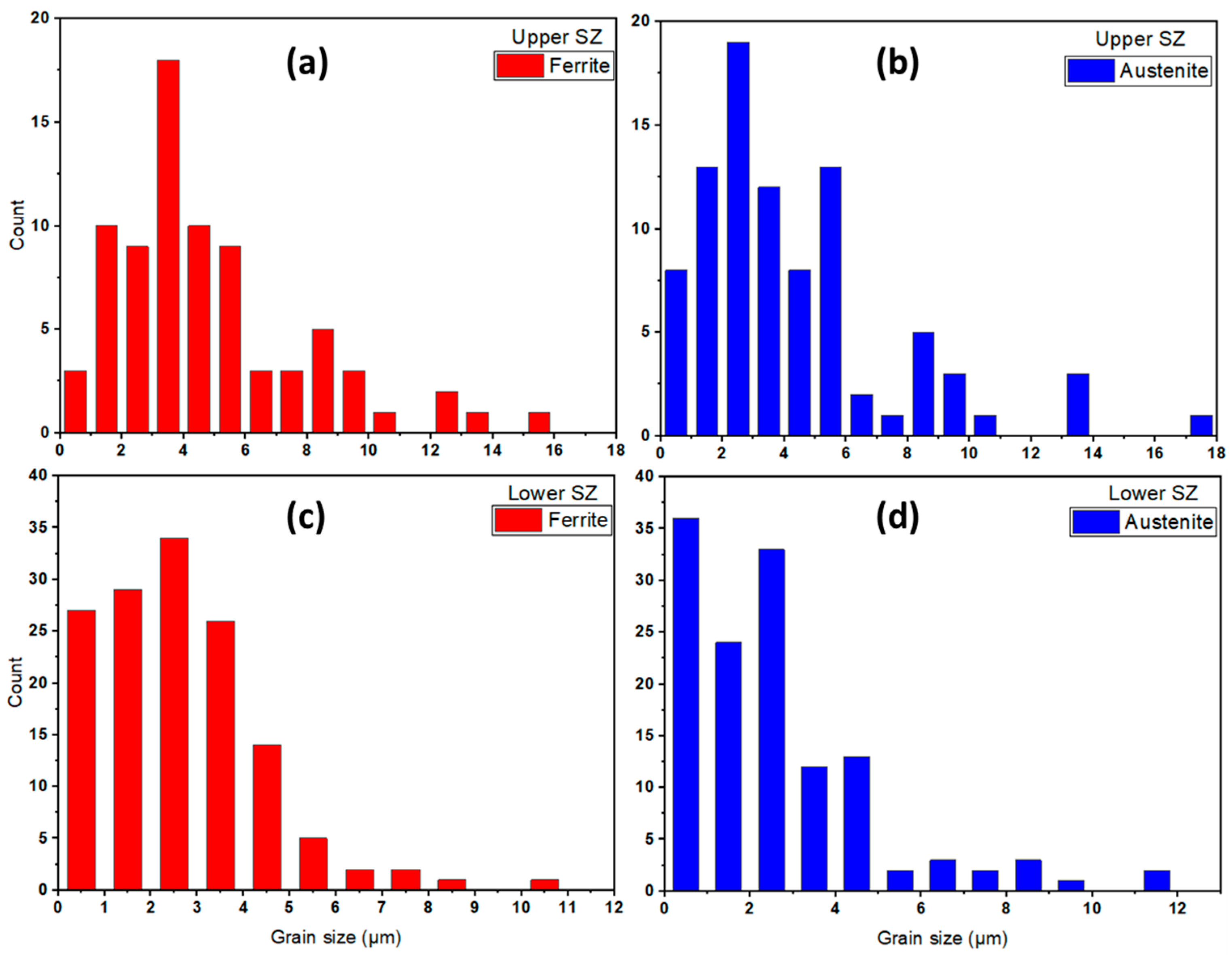
3.2. Microstructure Examination
3.3. Ferrite Content
3.4. Hardness and Tensile Properties
4. Conclusions
- The designed WC welding tool of the high pin to shoulder ratio (65%) was successfully used several times to conduct FSW of 5 mm thick DSS 2205 and produced defect-free butt joints. This design can be suggested to extend the WC tool life.
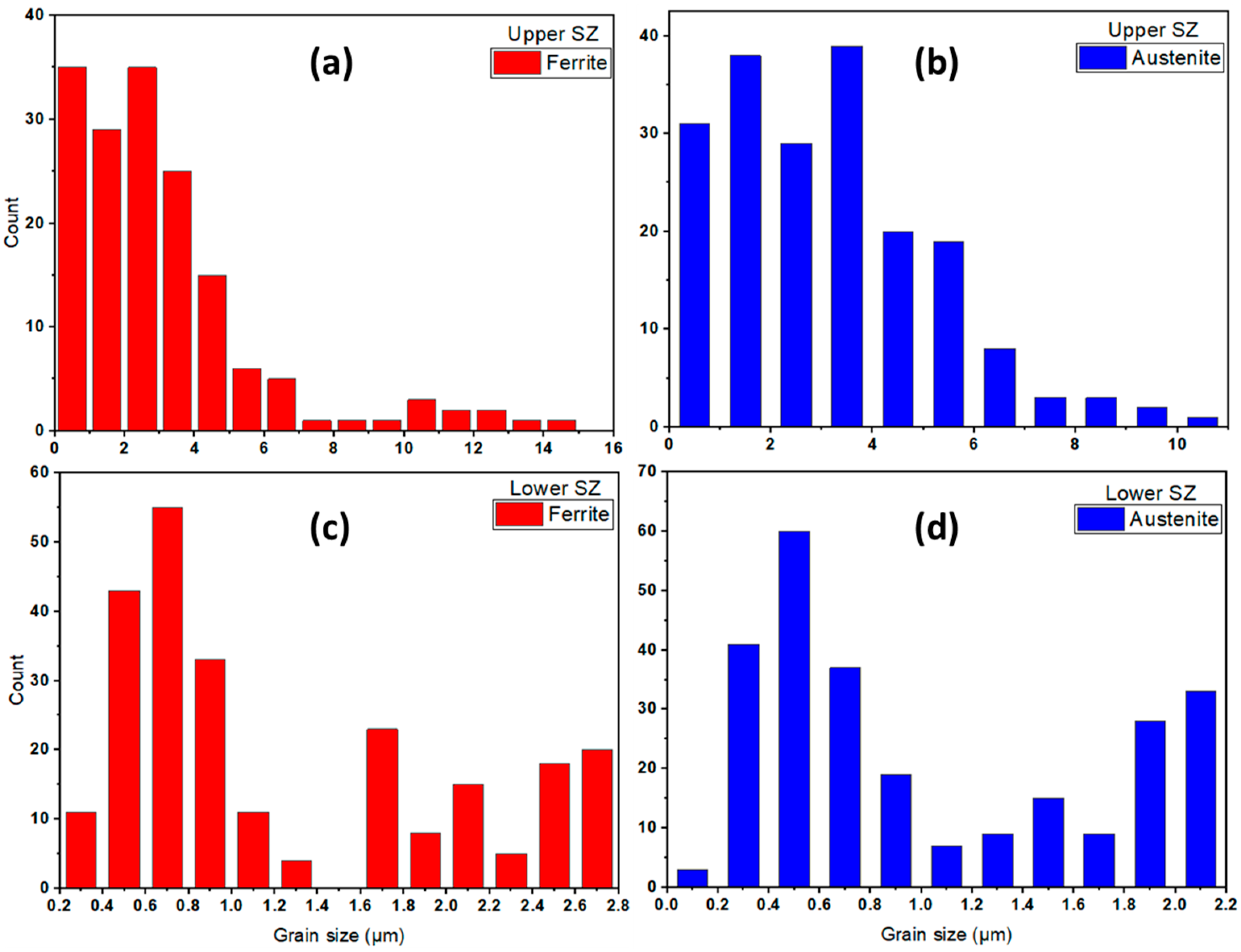
- The elongated ferrite matrix and austenite islands in the DSS 2205 BM were significantly refined after FSW in the stir zone and the average grain size of the ferrite and austenite reduced from 8.8 µm and 13.3 µm for the base material to 2.71 µm and 2.24 µm, respectively.
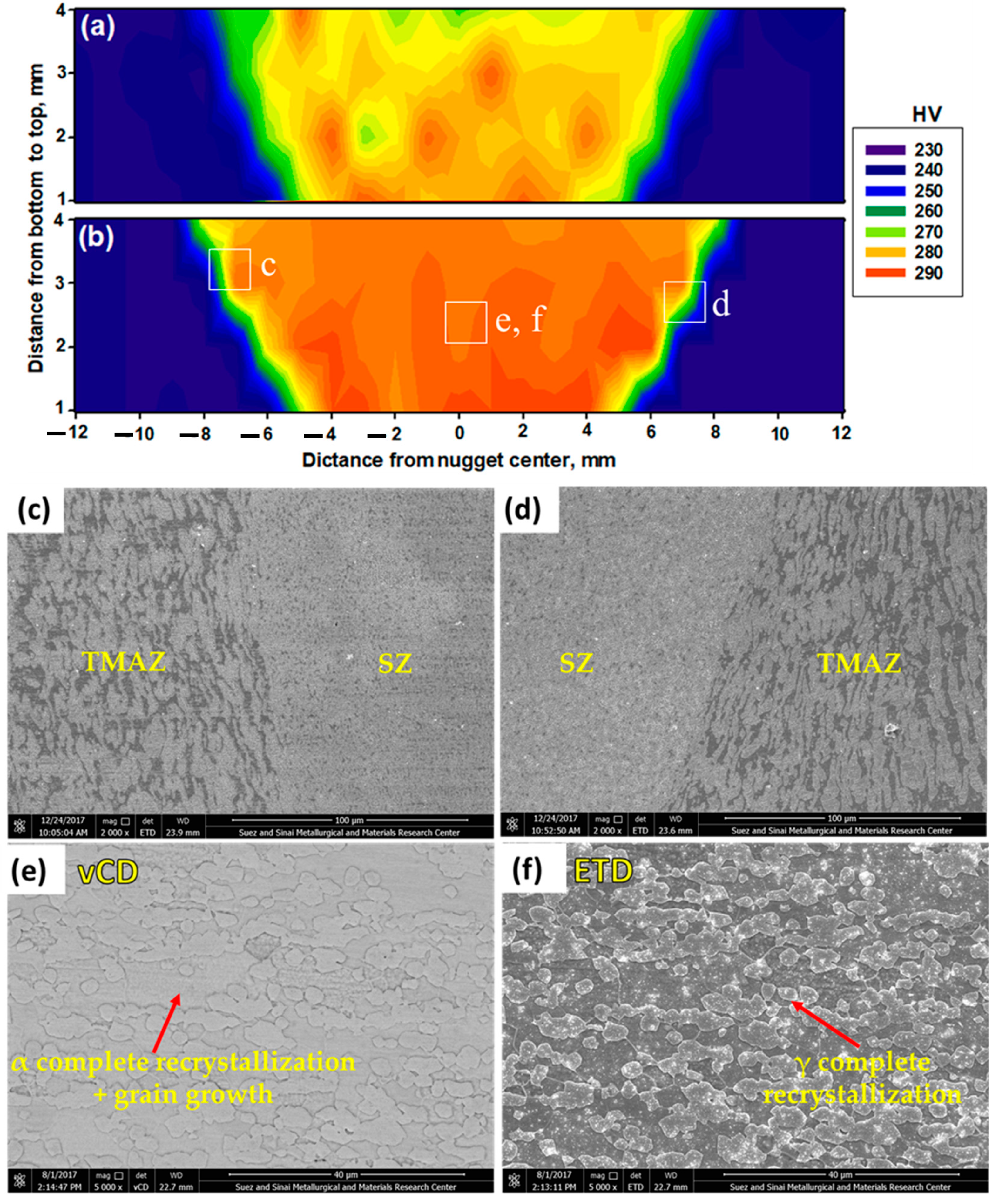
- The average hardness values of the SZ, TMAZ, and HAZ attained 273.2 HV, 264 HV, and 250 HV, respectively, for the butt joint welded at 600 rpm, 50 mm/min, and 14 kN. While, they reach the values of 285.9 HV, 274.2 HV, and 264 HV, respectively, for the joint welded at 300 rpm, 25 mm/min, and 20 kN, compared to the hardness of BM (235 HV).
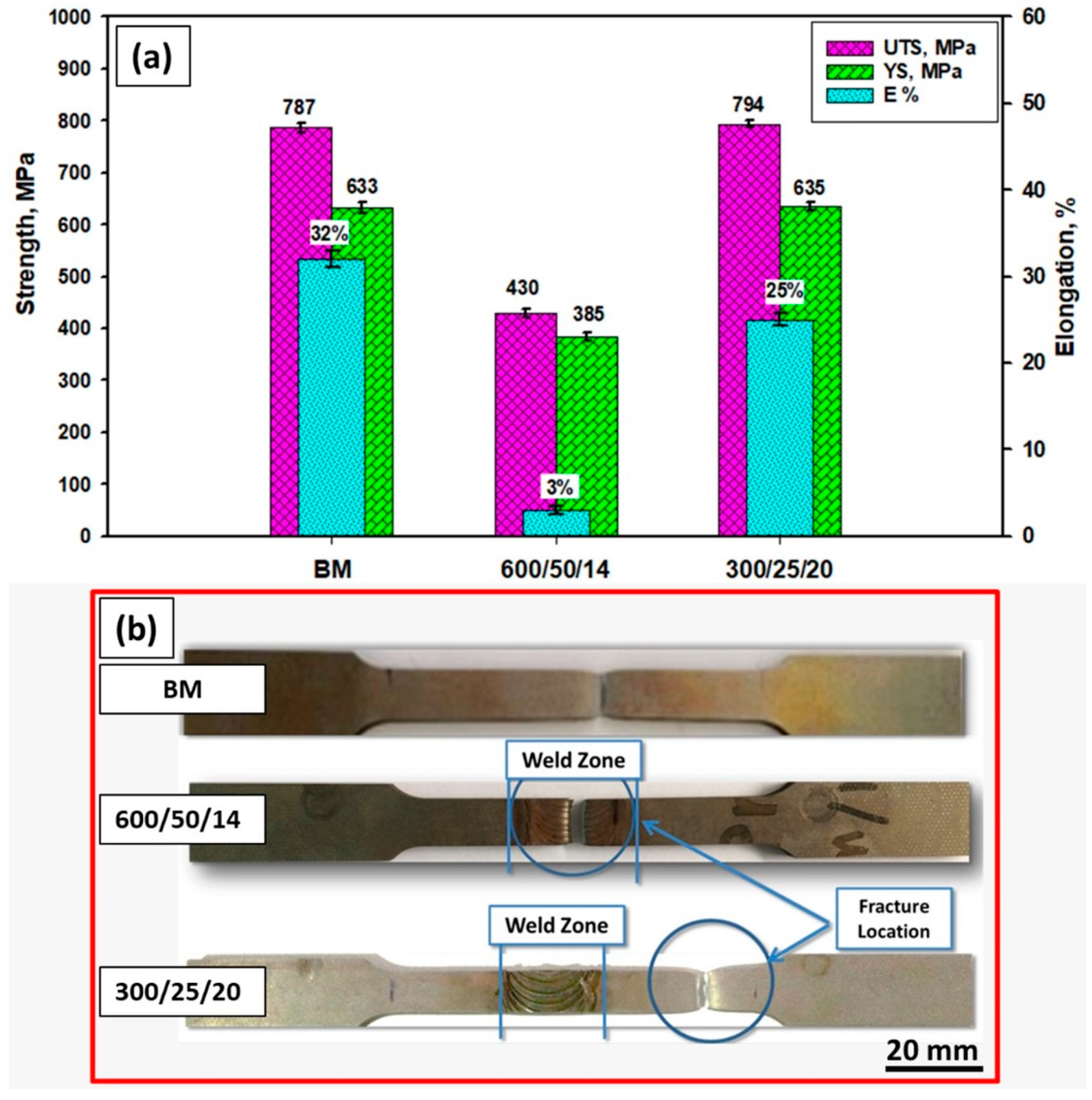
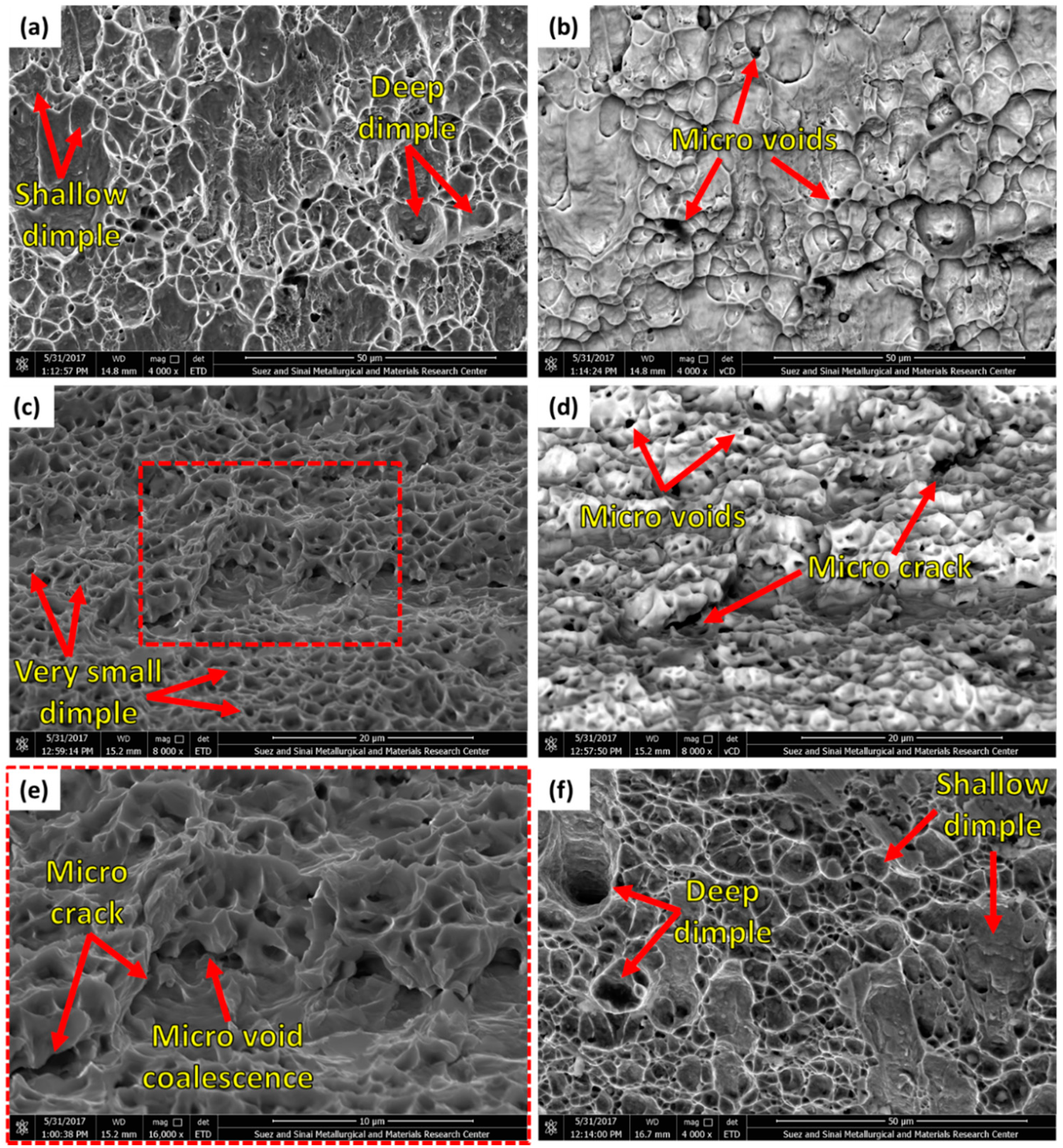
- The butt joint welded at 600 rpm, 50 mm/min, and 14 kN failed at the SZ with significantly lower tensile properties, whereas the joint welded at 300 rpm, 25 mm/min, and 20 kN failed at the BM, indicating high joint quality, with almost similar tensile properties to that of the BM.
Author Contributions
Funding
Institutional Review Board Statement
Informed Consent Statement
Data Availability Statement
Acknowledgments
Conflicts of Interest
References
- Ahmed, M.M.Z.; Abdelazem, K.A.; El-Sayed Seleman, M.M.; Alzahrani, B.; Touileb, K.; Jouini, N.; El-Batanony, I.G.; Abd El-Aziz, H.M. Friction stir welding of 2205 duplex stainless steel: Feasibility of butt joint groove filling in comparison to gas tungsten arc welding. Materials 2021, 14, 4597. [Google Scholar] [CrossRef] [PubMed]
- Saeid, T.; Abdollah-zadeh, A.; Shibayanagi, T.; Ikeuchi, K.; Assadi, H. On the formation of grain structure during friction stir welding of duplex stainless steel. Mater. Sci. Eng. A 2010, 527, 6484–6488. [Google Scholar] [CrossRef]
- Chaudhari, A.N.; Dixit, K.; Bhatia, G.S.; Singh, B.; Singhal, P.; Saxena, K.K. Welding behaviour of duplex stainless Steel AISI 2205: A Review. Mater. Today Proc. 2019, 18, 2731–2737. [Google Scholar] [CrossRef]
- Sathiya, P.; Aravindan, S.; Soundararajan, R.; Haq, A.N. Effect of shielding gases on mechanical and metallurgical properties of duplex stainless-steel welds. J. Mater. Sci. 2009, 44, 114–121. [Google Scholar] [CrossRef]
- Urena, A.; Otero, E.; Utrilla, M.V.; Munez, C.J. Weldability of a 2205 duplex stainless steel using plasma arc welding. J. Mater. Process. Technol. 2007, 182, 624–631. [Google Scholar] [CrossRef]
- Makhdoom, M.A.; Ahmad, A.; Kamran, M.; Abid, K.; Haider, W. Microstructural and electrochemical behavior of 2205 duplex stainless steel weldments. Surf. Interfaces 2017, 9, 189–195. [Google Scholar] [CrossRef]
- Sato, Y.S.; Nelson, T.W.; Sterling, C.J.; Steel, R.J.; Pettersson, C.-O. Microstructure and mechanical properties of friction stir welded SAF 2507 super duplex stainless steel. Mater. Sci. Eng. A 2005, 397, 376–384. [Google Scholar] [CrossRef]
- Subhash, N.; Prakash Marimuthu, K.; Jagadeesha, T. Finite Element Modelling of Temperature in Machining of Duplex Stainless Steel (DSS) 2205. J. Phys. Conf. Ser. 2019, 1240, 012147. [Google Scholar] [CrossRef]
- Chaudhari, A.Y.; Deshmukh, D.D. Metallurgical investigations on corrosion behavior of simple and heat treated duplex stainless steel 2205 exposed to corrosive media. IOP Conf. Ser. Mater. Sci. Eng. 2020, 810, 012048. [Google Scholar] [CrossRef]
- Xie, X.; Li, J.; Jiang, W.; Dong, Z.; Tu, S.T.; Zhai, X.; Zhao, X. Nonhomogeneous microstructure formation and its role on tensile and fatigue performance of duplex stainless steel 2205 multi-pass weld joints. Mater. Sci. Eng. A 2020, 786, 139426. [Google Scholar] [CrossRef]
- Emami, S.; Saeid, T. A comparative study on the microstructure development of friction stir welded 304 austenitic, 430 ferritic, and 2205 duplex stainless steels. Mater. Chem. Phys. 2019, 237, 121833. [Google Scholar] [CrossRef]
- Reyes-Hernández, D.; Manzano-Ramírez, A.; Encinas, A.; Sánchez-Cabrera, V.M.; de Jesús, M.; García-García, R.; Orozco, G.; Olivares-Ramírez, J.M. Addition of nitrogen to GTAW welding duplex steel 2205 and its effect on fatigue strength and corrosion. Fuel 2017, 198, 165–169. [Google Scholar] [CrossRef]
- Mourad, A.H.I.; Khourshid, A.; Sharef, T. Gas tungsten arc and laser beam welding processes effects on duplex stainless steel 2205 properties. Mater. Sci. Eng. A 2012, 549, 105–113. [Google Scholar] [CrossRef]
- Yousefieh, M.; Shamanian, M.; Saatchi, A. Influence of Heat Input in Pulsed Current GTAW Process on Microstructure and Corrosion Resistance of Duplex Stainless Steel Welds. J. Iron Steel Res. Int. 2011, 18, 65–69. [Google Scholar] [CrossRef]
- Ahmed, M.M.Z.; Ataya, S.; Seleman, M.M.E.S.; Allam, T.; Alsaleh, N.A.; Ahmed, E. Grain structure, crystallographic texture, and hardening behavior of dissimilar friction stir welded aa5083-o and aa5754-h14. Metals 2021, 11, 181. [Google Scholar] [CrossRef]
- Ahmed, M.M.Z.; Ataya, S.; El-Sayed Seleman, M.M.; Mahdy, A.M.A.; Alsaleh, N.A.; Ahmed, E. Heat input and mechanical properties investigation of friction stir welded aa5083/aa5754 and aa5083/aa7020. Metals 2021, 11, 68. [Google Scholar] [CrossRef]
- Ahmed, M.M.Z.; Ahmed, E.; Hamada, A.S.; Khodir, S.A.; El-Sayed Seleman, M.M.; Wynne, B.P. Microstructure and mechanical properties evolution of friction stir spot welded high-Mn twinning-induced plasticity steel. Mater. Des. 2016, 91, 378–387. [Google Scholar] [CrossRef]
- Ramachandran, S.; Lakshminarayanan, A.K.; Reed, P.A.S.; Dulieu-Barton, J.M. Development of high-fidelity imaging procedures to establish the local material behavior in friction stir welded stainless steel joints. Metals 2019, 9, 592. [Google Scholar] [CrossRef] [Green Version]
- Ahmed, M.M.Z.; El-Sayed Seleman, M.M.; Shazly, M.; Attallah, M.M.; Ahmed, E. Microstructural Development and Mechanical Properties of Friction Stir Welded Ferritic Stainless Steel AISI 409. J. Mater. Eng. Perform. 2019, 28, 6391–6406. [Google Scholar] [CrossRef]
- Ahmed, M.M.Z.; Wynne, B.P.; El-Sayed Seleman, M.M.; Rainforth, W.M. A comparison of crystallographic texture and grain structure development in aluminum generated by friction stir welding and high strain torsion. Mater. Des. 2016, 103, 259–267. [Google Scholar] [CrossRef]
- Hoziefa, W.; Toschi, S.; Ahmed, M.M.Z.; Morri, A.; Mahdy, A.A.; El-Sayed Seleman, M.M.; El-Mahallawi, I.; Ceschini, L.; Atlam, A. Influence of friction stir processing on the microstructure and mechanical properties of a compocast AA2024-Al2O3 nanocomposite. Mater. Des. 2016, 106, 273–284. [Google Scholar] [CrossRef]
- Ahmed, M.M.Z.; Habba, M.I.A.; Jouini, N.; Alzahrani, B.; El-Sayed Seleman, M.M.; El-Nikhaily, A. Bobbin tool friction stir welding of aluminum using different tool pin geometries: Mathematical models for the heat generation. Metals 2021, 11, 438. [Google Scholar] [CrossRef]
- Memon, S.; Fydrych, D.; Fernandez, A.C.; Derazkola, H.A.; Derazkola, H.A. Effects of fsw tool plunge depth on properties of an al-mg-si alloy t-joint: Thermomechanical modeling and experimental evaluation. Materials 2021, 14, 4754. [Google Scholar] [CrossRef]
- Janeczek, A.; Tomków, J.; Fydrych, D. The influence of tool shape and process parameters on the mechanical properties of aw-3004 aluminium alloy friction stir welded joints. Materials 2021, 14, 3244. [Google Scholar] [CrossRef]
- Ahmed, M.M.Z.; El-Sayed Seleman, M.M.; Zidan, Z.A.; Ramadan, R.M.; Ataya, S.; Alsaleh, N.A. Microstructure and mechanical properties of dissimilar friction stir welded AA2024-T4/AA7075-T6 T-butt joints. Metals 2021, 11, 128. [Google Scholar] [CrossRef]
- Ahmed, M.M.Z.; Ataya, S.; El-Sayed Seleman, M.M.; Ammar, H.R.; Ahmed, E. Friction stir welding of similar and dissimilar AA7075 and AA5083. J. Mater. Process. Technol. 2017, 242, 77–91. [Google Scholar] [CrossRef]
- Ahmed, M.M.Z.; Jouini, N.; Alzahrani, B.; Seleman, M.M.E.-S.; Jhaheen, M. Properties, Dissimilar Friction Stir Welding of AA2024 and AISI 1018: Microstructure and Mechanical Properties. Metals 2021, 11, 330. [Google Scholar] [CrossRef]
- Sarlak, H.; Atapour, M.; Esmailzadeh, M. Corrosion Behavior of Friction Stir Welded Lean Duplex Stainless Steel; Elsevier Ltd.: Amsterdam, The Netherland, 2015; Volume 66, ISBN 8415683111. [Google Scholar]
- Wang, W.; Hu, Y.; Wu, T.; Zhao, D.; Zhao, H. Effect of Rotation Speed on Microstructure and Mechanical Properties of Friction-Stir-Welded 2205 Duplex Stainless Steel. Adv. Mater. Sci. Eng. 2020, 2020, 151797. [Google Scholar] [CrossRef]
- Saeid, T.; Abdollah-zadeh, A.; Assadi, H.; Malek Ghaini, F. Effect of friction stir welding speed on the microstructure and mechanical properties of a duplex stainless steel. Mater. Sci. Eng. A 2008, 496, 262–268. [Google Scholar] [CrossRef]
- Tonelli, L.; Morri, A.; Toschi, S.; Shaaban, M.; Ammar, H.R.; Ahmed, M.M.Z.; Ramadan, R.M. Effect of FSP parameters and tool geometry on microstructure, hardness, and wear properties of AA7075 with and without reinforcing B4C ceramic particles. Int. J. Adv. Manuf. Technol. 2019, 102, 9–12. [Google Scholar] [CrossRef]
- Kim, Y.G.; Fujii, H.; Tsumura, T.; Komazaki, T.; Nakata, K. Three defect types in friction stir welding of aluminum die casting alloy. Mater. Sci. Eng. A 2006, 415, 250–254. [Google Scholar] [CrossRef]
- Agha Amini Fashami, H.; Bani Mostafa Arab, N.; Hoseinpour Gollo, M.; Nami, B. Numerical and experimental investigation of defects formation during friction stir processing on AZ91. SN Appl. Sci. 2021, 3, 108. [Google Scholar] [CrossRef]
- Zandsalimi, S.; Heidarzadeh, A.; Saeid, T. Dissimilar friction-stir welding of 430 stainless steel and 6061 aluminum alloy: Microstructure and mechanical properties of the joints. Proc. Inst. Mech. Eng. Part L J. Mater. Des. Appl. 2019, 233, 1791–1801. [Google Scholar] [CrossRef]
- Giorjão, R.A.R.; Pereira, V.F.; Terada, M.; de Fonseca, E.B.; Marinho, R.R.; Garcia, D.M.; Tschiptschin, A.P. Microstructure and mechanical properties of friction stir welded 8 mm pipe SAF 2507 super duplex stainless steel. J. Mater. Res. Technol. 2019, 8, 243–249. [Google Scholar] [CrossRef]
- Dong, J.; Zhang, D.; Zhang, W.; Zhang, W.; Qiu, C. Microstructure evolution during dissimilar friction stir welding of AA7003-T4 and AA6060-T4. Materials 2018, 11, 342. [Google Scholar] [CrossRef] [Green Version]
- Zayed, E.M.; El-Tayeb, N.S.M.; Ahmed, M.M.; Rashad, R.M. Development and Characterization of AA5083 Reinforced with SiC and Al2O3 Particles by Friction Stir Processing. In Engineering Design Applications; Öchsner, A., Altenbach, H., Eds.; Springer International Publishing: Cham, Switzerland, 2019; pp. 11–26. ISBN 978-3-319-79005-3. [Google Scholar]
- Hamada, A.S.; Järvenpää, A.; Ahmed, M.M.Z.; Jaskari, M.; Wynne, B.P.; Porter, D.A.; Karjalainen, L.P. The microstructural evolution of friction stir welded AA6082-T6 aluminum alloy during cyclic deformation. Mater. Sci. Eng. A 2015, 642, 366–376. [Google Scholar] [CrossRef]
- Santos, T.F.A.; Idagawa, H.S.; Ramirez, A.J. Thermal history in UNS S32205 duplex stainless steel friction stir welds. Sci. Technol. Weld. Join. 2014, 19, 150–156. [Google Scholar] [CrossRef]
- Wang, L.; Zhao, P.; Pan, J.; Tan, L.; Zhu, K. Investigation on microstructure and mechanical properties of double-sided synchronous TIP TIG arc butt welded duplex stainless steel. Int. J. Adv. Manuf. Technol. 2021, 112, 303–312. [Google Scholar] [CrossRef]
- Fouad, D.M.; El-garaihy, W.H.; Ahmed, M.M.Z.; Albaijan, I.; Seleman, M.M.E.; Salem, H.G. Grain Structure Evolution and Mechanical Properties of Multi-Channel Spiral Twist Extruded AA5083. Metals 2021, 11, 1276. [Google Scholar] [CrossRef]
- Fouad, D.M.; El-Garaihy, W.H.; Ahmed, M.M.Z.; El-Sayed Seleman, M.M.; Salem, H.G. Influence of multi-channel spiral twist extrusion (MCSTE) processing on structural evolution, crystallographic texture and mechanical properties of AA1100. Mater. Sci. Eng. A 2018, 737, 166–175. [Google Scholar] [CrossRef]
- Abubaker, H.M.; Merah, N.; Al-badour, F.A.; Albinmousa, J.; Sorour, A.A. Influence of friction stir processing on mechanical behavior of 2507 SDSS. Metals 2020, 10, 369. [Google Scholar] [CrossRef] [Green Version]
- Shokri, V.; Sadeghi, A.; Sadeghi, M.H. Effect of friction stir welding parameters on microstructure and mechanical properties of DSS–Cu joints. Mater. Sci. Eng. A 2017, 693, 111–120. [Google Scholar] [CrossRef] [Green Version]
- Magnani, M.; Terada, M.; Lino, A.O.; Tallo, V.P.; da Fonseca, E.B.; Santos, T.F.A.; Ramirez, A.J. Microstructural and electrochemical characterization of friction stir welded duplex stainless steels. Int. J. Electrochem. Sci. 2014, 9, 2966–2977. [Google Scholar]
- Calliari, I.; Straffelini, G.; Ramous, E. Investigation of secondary phase effect on 2205 DSS fracture toughness. Mater. Sci. Technol. 2010, 26, 81–86. [Google Scholar] [CrossRef]
- Sorger, G.; Sarikka, T.; Vilaça, P.; Santos, T.G. Effect of processing temperatures on the properties of a high-strength steel welded by FSW. Weld. World 2018, 62, 1173–1185. [Google Scholar] [CrossRef] [Green Version]
- Ghadar, S.; Momeni, A.; Khademi, E.; Kazemi, S. Effect of rotation and traverse speeds on the microstructure and mechanical properties of friction stir processed 2205 duplex stainless steel. Mater. Sci. Eng. B Solid-State Mater. Adv. Technol. 2021, 263, 114813. [Google Scholar] [CrossRef]

| C | Mn | Si | Cr | Ni | Mo | P | S | V | Cu | Fe |
|---|---|---|---|---|---|---|---|---|---|---|
| 0.030 | 0.838 | 0.001 | 21.500 | 5.290 | 3.660 | 0.024 | 0.001 | 0.132 | 0.093 | Balance |
| Sample Code | Rotational Speed (rpm) | Travel Speed (mm/min) | Downward Force (kN) |
|---|---|---|---|
| S1 | 600 | 50 | 14 |
| S2 | 300 | 50 | 14 |
| S3 | 300 | 25 | 14 |
| S4 | 300 | 25 | 20 |
| Shoulder diameter | 20 mm |
| Shoulder feature | concave shoulder |
| Pin length | 4.5 mm |
| Pin profile | Tapered cylindrical |
| Pin diameter | Pin base: 13 mm |
| Pin tip: 9 mm | |
| Tilt angle | 3° |
| Specimen No. | Figure | Visual Appearance | Surface Defect | Test Results | |
|---|---|---|---|---|---|
| Flash | Groove | ||||
| S1 | Figure 3a | Good | much | Non | Accepted |
| S2 | Figure 3b | Partially good | Small | Detected | Rejected |
| S3 | Figure 3c | Bad | Small | Detected | Rejected |
| S4 | Figure 3d | Very good | Very small | Non | Accepted |
| Sample | FSW Conditions (rpm)/(mm/min)/(kN) | Ferrite Number Readings (%) | AV of Measured α Phase | Calculated γ Phase | ||||
|---|---|---|---|---|---|---|---|---|
| BM | - | 50 | 49 | 51 | 50 | 52 | 50.4 | 49.6 |
| S1-SZ | 600/50/14 | 53 | 46 | 49 | 49 | 50 | 49.4 | 50.6 |
| S4-SZ | 300/25/20 | 48 | 46 | 48 | 51 | 47 | 48.0 | 52.0 |
Publisher’s Note: MDPI stays neutral with regard to jurisdictional claims in published maps and institutional affiliations. |
© 2021 by the authors. Licensee MDPI, Basel, Switzerland. This article is an open access article distributed under the terms and conditions of the Creative Commons Attribution (CC BY) license (https://creativecommons.org/licenses/by/4.0/).
Share and Cite
Ahmed, M.M.Z.; Hajlaoui, K.; El-Sayed Seleman, M.M.; Elkady, M.F.; Ataya, S.; Latief, F.H.; Habba, M.I.A. Microstructure and Mechanical Properties of Friction Stir Welded 2205 Duplex Stainless Steel Butt Joints. Materials 2021, 14, 6640. https://doi.org/10.3390/ma14216640
Ahmed MMZ, Hajlaoui K, El-Sayed Seleman MM, Elkady MF, Ataya S, Latief FH, Habba MIA. Microstructure and Mechanical Properties of Friction Stir Welded 2205 Duplex Stainless Steel Butt Joints. Materials. 2021; 14(21):6640. https://doi.org/10.3390/ma14216640
Chicago/Turabian StyleAhmed, Mohamed M. Z., Khalil Hajlaoui, Mohamed M. El-Sayed Seleman, Mahmoud F. Elkady, Sabbah Ataya, Fahamsyah H. Latief, and Mohamed I. A. Habba. 2021. "Microstructure and Mechanical Properties of Friction Stir Welded 2205 Duplex Stainless Steel Butt Joints" Materials 14, no. 21: 6640. https://doi.org/10.3390/ma14216640
APA StyleAhmed, M. M. Z., Hajlaoui, K., El-Sayed Seleman, M. M., Elkady, M. F., Ataya, S., Latief, F. H., & Habba, M. I. A. (2021). Microstructure and Mechanical Properties of Friction Stir Welded 2205 Duplex Stainless Steel Butt Joints. Materials, 14(21), 6640. https://doi.org/10.3390/ma14216640