
Optimal Placement of Viscoelastic Vibration Dampers for Kirchhoff Plates Based on PSO Method


Abstract
:1. Introduction
2. Theoretical Background
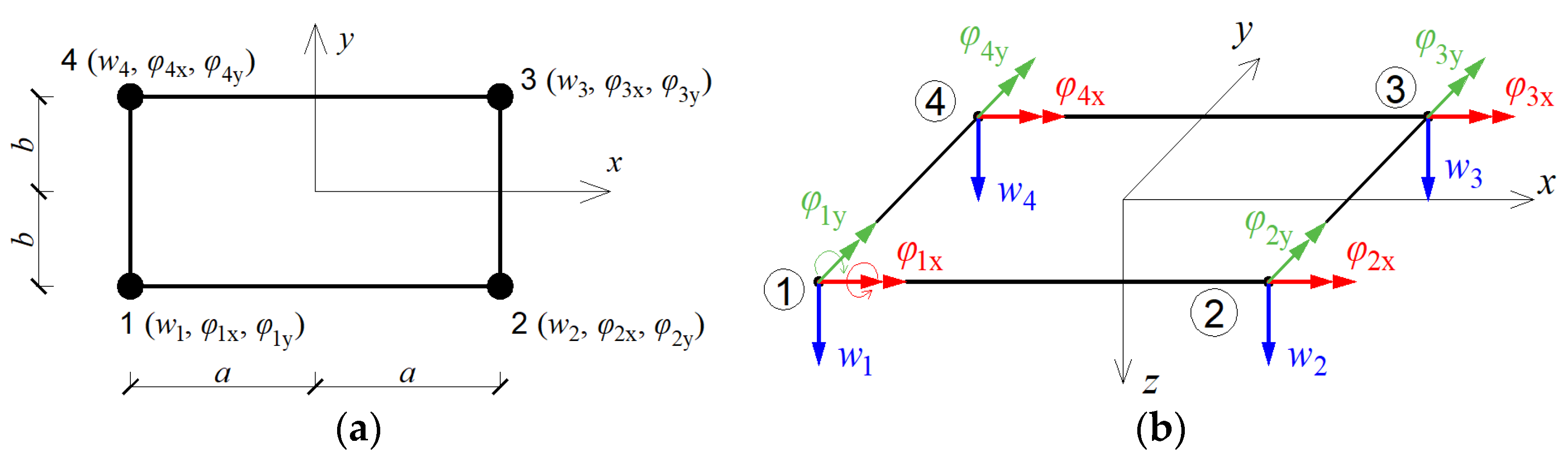
2.1. Description of Plate Model according to Finite Element Method
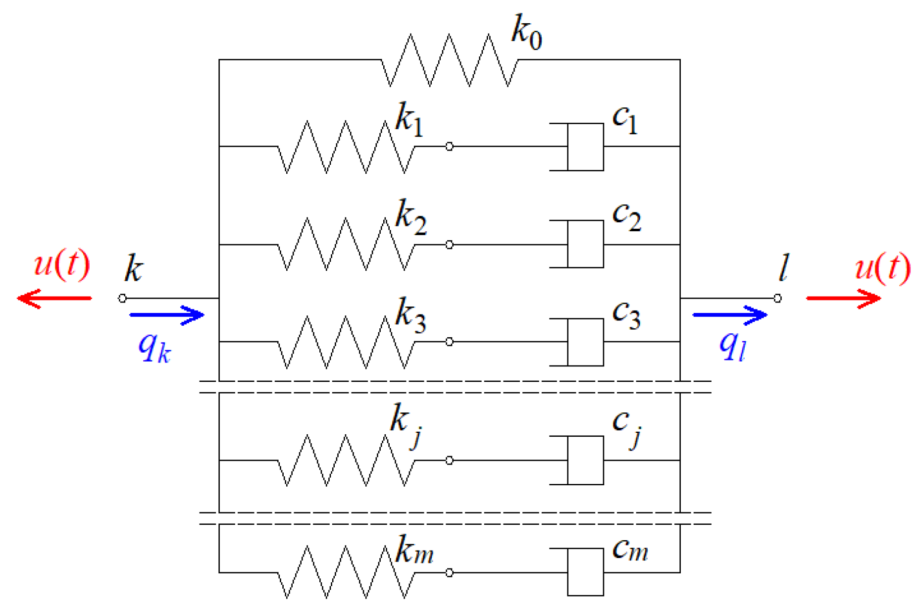
2.2. The Viscoelastic Damper Model
2.3. The Equation of Motion of the Plate with VE Dampers and Solution of Eigenproblem
2.4. Fundamentals of Particle Swarm Method
- Adopting initial positions and initial velocities of particles;
- Checking the limiting condition of termination;
- Calculation of the value of the objective function for the positions of individual particles;
- Updating the best position of each particle and the best position of the particle in the vicinity of each particle after k iterations;
- Determination of new positions and velocities of particles according to Formulas (24) and (25);
- Repeating steps 2–5 until the accepted criteria for stopping the calculations are met.
3. Numerical Examples
- Plate discretization with FEM mesh with dimensions of or ;
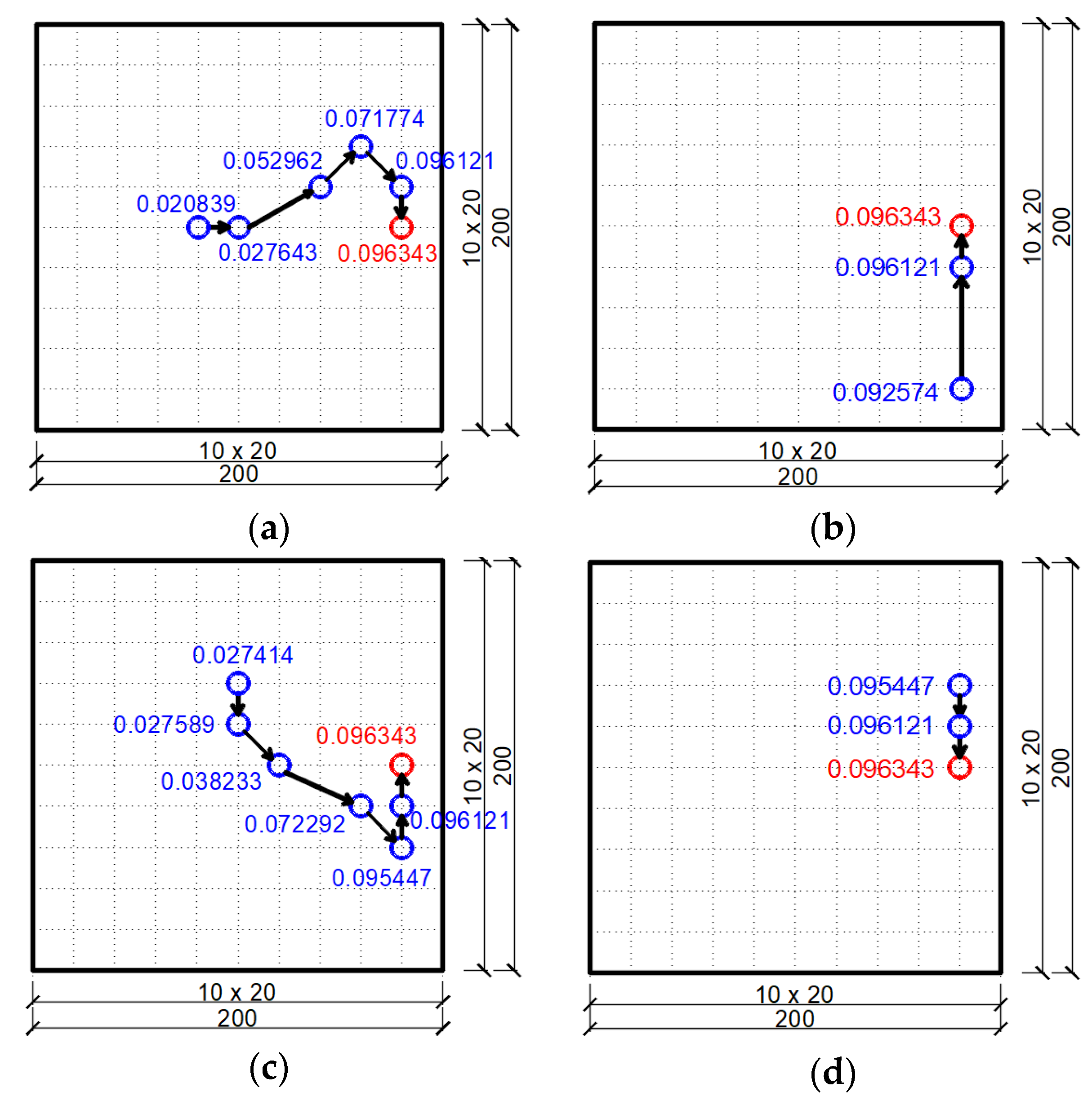
- The assumed objective function—non-dimensional damping ratio of the first mode of vibration;
- Possible locations of the viscoelastic dampers—internal nodes of the FEM mesh discretizing the plate;
- The method of determining the optimal position of the assumed number of dampers—obtaining the maximum value of the objective function;
- The initial velocities of the swarm particles in each environment are assumed to be zero;
- Accepted values of cognitive parameter and social parameter: ;
- Accepted value of the inertia weight: ;
- The adopted maximum number of iterations of the PSO algorithm: 15.
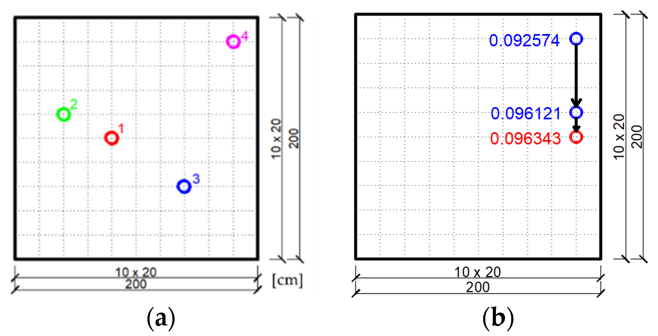
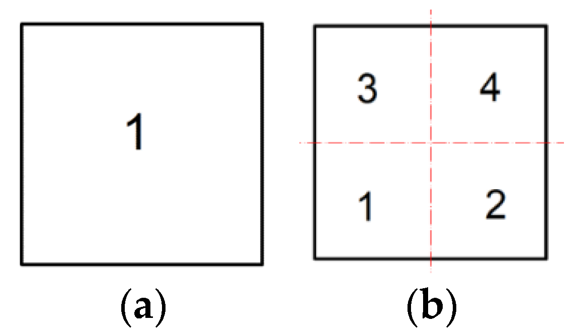
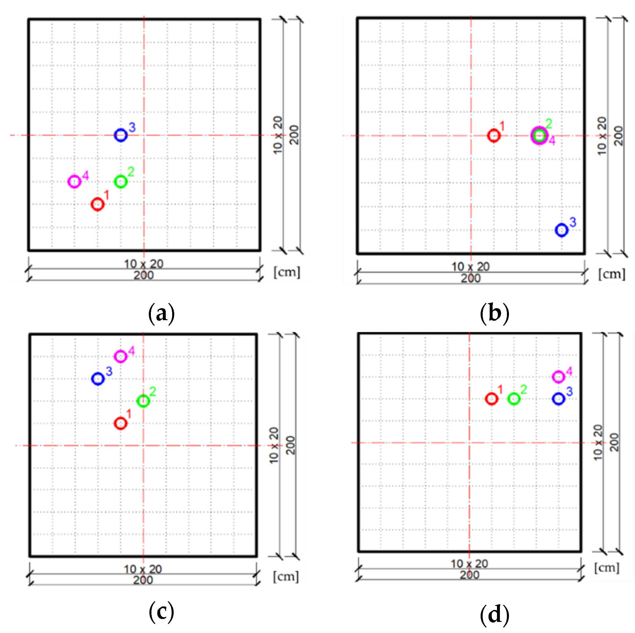
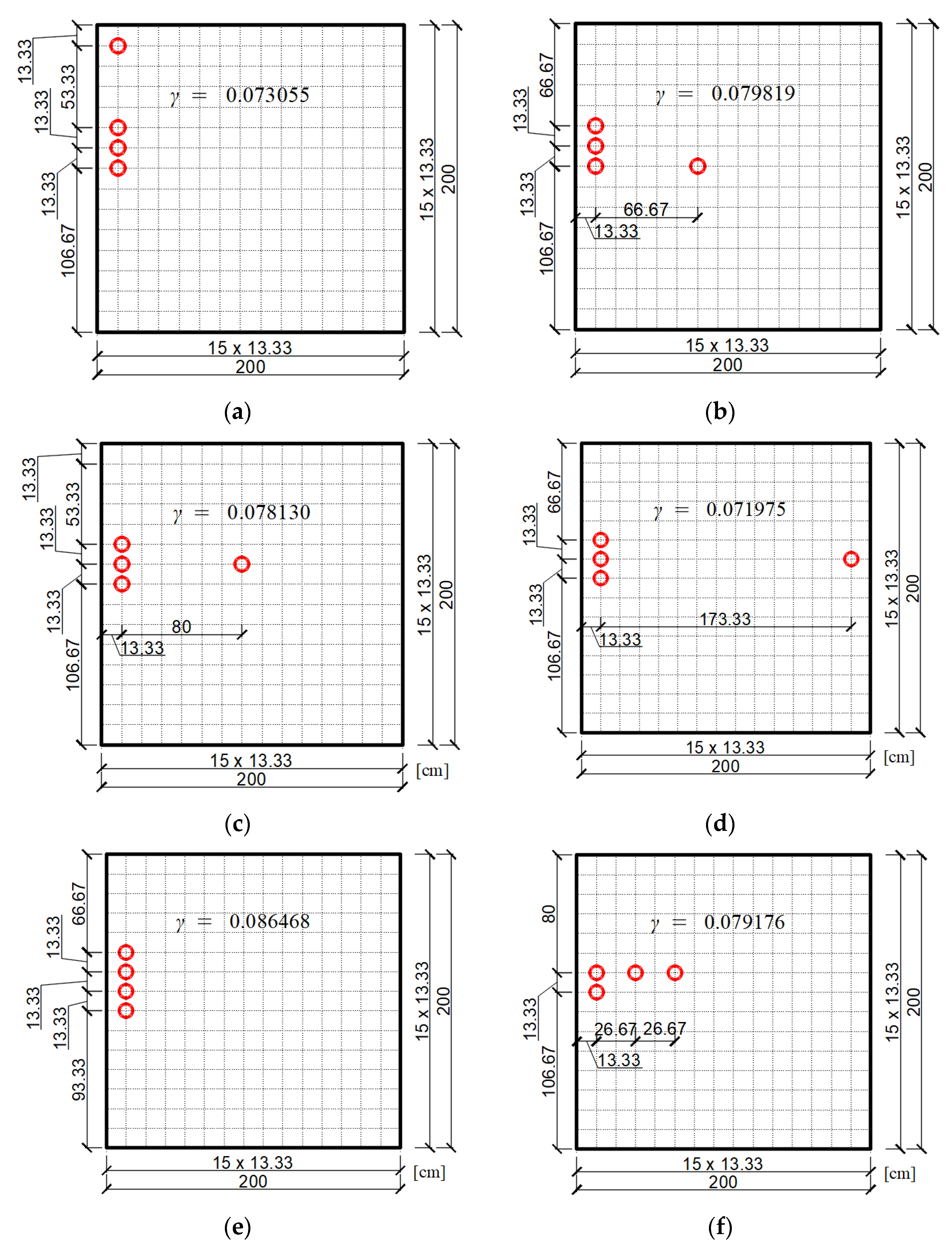
3.1. Example No 1
- One neighborhood is assumed within the plate and four potential positions of swarm particles are randomly selected;
- Four neighborhoods are assumed within the plate and four potential positions of swarm particles in each neighborhood are randomly selected
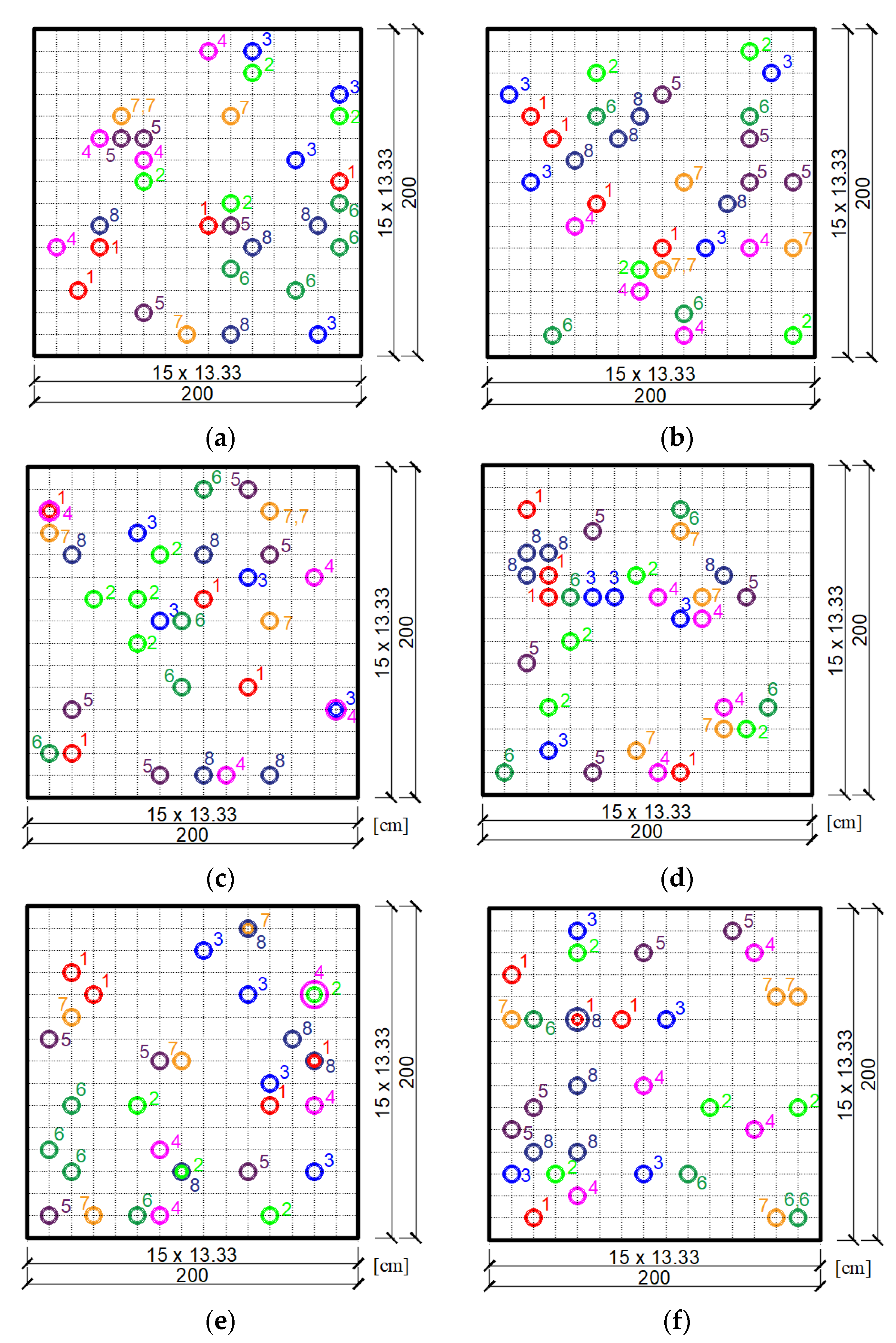
3.2. Example No 2
4. Discussion
5. Conclusions
Author Contributions
Funding
Institutional Review Board Statement
Informed Consent Statement
Data Availability Statement
Conflicts of Interest
References
- Movaffaghi, H.; Friberg, O. Optimal placement of dampers in structures using genetic algorithm. Eng. Comput. 2006, 23, 597–606. [Google Scholar] [CrossRef]
- Bogdanovic, A.; Rakicevic, Z.T.; Filipovski, D. Comparison between two optimization procedures for damper location in steel frame structures. In Proceedings of the Second European Conference on Earthquake Engineering and Seismology, Instanbul, Turkey, 25–29 August 2014. [Google Scholar]
- Wang, H.; Li, A.; Jiao, C.; Spencer, B.F. Damper placement for seismic control of super-long-span suspension bridges based on the first-order optimization method. Sci. China Ser. E Technol. Sci. 2010, 53, 2008–2014. [Google Scholar] [CrossRef]
- Singh, M.P.; Moreschi, L.M. Optimal placement of dampers for passive response control. Earthq. Eng. Struct. Dyn. 2002, 31, 955–976. [Google Scholar] [CrossRef]
- Lavan, O.; Levy, R. Optimal design of supplemental viscous dampers for linear framed structures. Earthq. Eng. Struct. Dyn. 2006, 35, 337–356. [Google Scholar] [CrossRef]
- Bogdanovic, A.; Rakicevic, Z. Optimal Damper Placement Using Combined Fitness Function. Front. Built Environ. 2019, 5, 4. [Google Scholar] [CrossRef] [Green Version]
- Kokil, A.S.; Shrikhande, M. Optimal Placement of Supplemental Dampers in Seismic Design of Structures. JSEE Fall 2007, 9, 125–135. [Google Scholar]
- Fujita, K.; Moustafa, A.; Takewaki, I. Optimal placement of viscoelastic dampers and supporting members under variable critical excitations. Earthq. Struct. 2010, 1, 43–67. [Google Scholar] [CrossRef]
- Gürgöze, M.; Müller, P. Optimal positioning of dampers in multi-body systems. J. Sound Vib. 1992, 158, 517–530. [Google Scholar] [CrossRef]
- Sulaksitaningrum, R.; Umniati, B.S.; Sarassantika, I.P.E.; Casita, C.B.; Pratama, M.M.A.; Santoso, E.; Sulton, M. The optimal damper placement configuration for three-dimensional RC building. IOP Conf. Ser. Mater. Sci. Eng. 2019, 669, 012056. [Google Scholar] [CrossRef]
- Estekanchi, H.E.; Basim, M.C. Optimal damper placement in steel frames by the Endurance Time method. Struct. Des. Tall Spéc. Build. 2011, 20, 612–630. [Google Scholar] [CrossRef]
- Kennedy, J.; Eberhart, R. Particle swarm optimization. In Proceedings of the ICNN’95—International Conference on Neural Networks, Perth, Australia, 27 November–1 December 1995; Volume 4, pp. 1942–1948. [Google Scholar]
- Perez, R.; Behdinan, K. Particle swarm approach for structural design optimization. Comput. Struct. 2007, 85, 1579–1588. [Google Scholar] [CrossRef]
- Engelbrecht, A. Particle swarm optimization: Velocity initialization. In Proceedings of the 2012 IEEE Congress on Evolutionary Computation, Brisbane, QLD, Australia, 10–15 June 2012; Volume 10, pp. 1–8. [Google Scholar]
- Harrison, K.R.; Ombuki-Berman, B.M.; Engelbrecht, A.P. Optimal parameter regions for particle swarm optimization algorithms. In Proceedings of the 2017 IEEE Congress on Evolutionary Computation (CEC), Donostia, Spain, 5–8 June 2017; Volume 5, pp. 349–356. [Google Scholar]
- Harrison, K.R.; Engelbrecht, A.P.; Ombuki-Berman, B.M. Optimal parameter regions and the time-dependence of control parameter values for the particle swarm optimization algorithm. Swarm Evol. Comput. 2018, 41, 20–35. [Google Scholar] [CrossRef] [Green Version]
- Shao, L.; Bai, Y.; Qiu, Y.; Du, Z. Particle Swarm Optimization Algorithm Based on Semantic Relations and Its Engineering Applications. Syst. Eng. Procedia 2012, 5, 222–227. [Google Scholar] [CrossRef] [Green Version]
- Wang, H.; Sun, H.; Li, C.; Rahnamayan, S.; Pan, J.-S. Diversity enhanced particle swarm optimization with neighborhood search. Inf. Sci. 2013, 223, 119–135. [Google Scholar] [CrossRef]
- Imran, M.; Hashim, R.; Khalid, N.E.A. An Overview of Particle Swarm Optimization Variants. Procedia Eng. 2013, 53, 491–496. [Google Scholar] [CrossRef] [Green Version]
- Cleghorn, C.W.; Engelbrecht, A.P. A generalized theoretical deterministic particle swarm model. Swarm Intell. 2014, 8, 35–59. [Google Scholar] [CrossRef]
- Du, W.-B.; Gao, Y.; Liu, C.; Zheng, Z.; Wang, Z. Adequate is better: Particle swarm optimization with limited-information. Appl. Math. Comput. 2015, 268, 832–838. [Google Scholar] [CrossRef]
- Harrison, K.R.; Engelbrecht, A.P.; Ombuki-Berman, B.M. Self-adaptive particle swarm optimization: A review and analysis of convergence. Swarm Intell. 2017, 12, 187–226. [Google Scholar] [CrossRef] [Green Version]
- Freitas, D.; Lopes, L.G.; Morgado-Dias, F. Particle Swarm Optimisation: A Historical Review Up to the Current Developments. Entropy 2020, 22, 362. [Google Scholar] [CrossRef] [Green Version]
- Christensen, R.M. Theory of Viscoelasticity, 2nd ed.; Academic Press: Cambridge, MA, USA, 1982. [Google Scholar]
- Park, S. Analytical modeling of viscoelastic dampers for structural and vibration control. Int. J. Solids Struct. 2001, 38, 8065–8092. [Google Scholar] [CrossRef]
- Zienkiewicz, O.; Taylor, R.; Zhu, J. The Finite Element Method: Its Basis and Fundamentals; Elsevier: Amsterdam, The Netherlands, 2013. [Google Scholar]
- Bathe, K.J. Finite Element Procedures, 2nd ed.; Prentice Hall: Watertown, MA, USA, 2016. [Google Scholar]
- Kuczma, M. Foundations of structural mechanics with shape memory. In Numerical Modeling, 1st ed.; University of Zielona Góra Publishing House: Zielona Góra, Poland, 2010. (In Polish) [Google Scholar]
- Pawlak, Z.; Lewandowski, R. The continuation method for the eigenvalue problem of structures with viscoelastic dampers. Comput. Struct. 2013, 125, 53–61. [Google Scholar] [CrossRef]
- Lewandowski, R.; Baum, M. Dynamic characteristics of multilayered beams with viscoelastic layers described by the fractional Zener model. Arch. Appl. Mech. 2015, 85, 1793–1814. [Google Scholar] [CrossRef]
- Łasecka-Plura, M.; Lewandowski, R. The subspace iteration method for nonlinear eigenvalue problems occurring in the dynamics of structures with viscoelastic elements. Comput. Struct. 2021, 254, 106571. [Google Scholar] [CrossRef]
- Kasai, K.; Sato, D. A constitutive rule for viscoelastic material considering heat conduction and heat transfer. In Proceedings of the Second International Conference on Urban Earthquake Engineering, Tokyo, Japan, 7–8 March 2005. [Google Scholar]


| Natural Frequencies ω [rad/s] | |||
|---|---|---|---|
| Mode | Plate without Dampers with Different FEM Discretization | Plate with Dampers Located according to Figure 9e | |
| Mesh 10 × 10 | Mesh 15 × 15 | ||
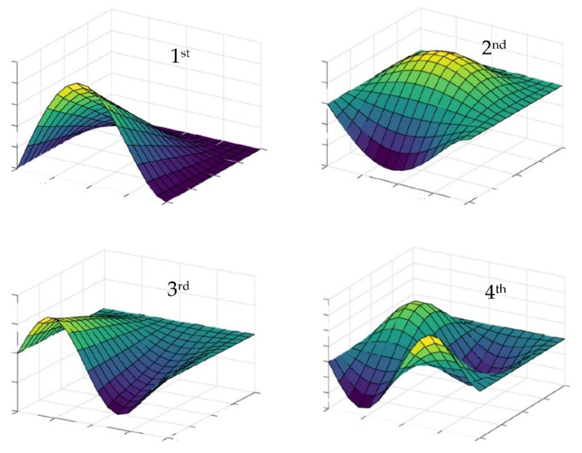
| 1 | 67.808 | 67.802 | 72.896 |
| 2 | 138.279 | 138.812 | 141.802 |
| 3 | 200.620 | 200.449 | 201.151 |
| 4 | 271.529 | 273.269 | 273.679 |
Publisher’s Note: MDPI stays neutral with regard to jurisdictional claims in published maps and institutional affiliations. |
© 2021 by the authors. Licensee MDPI, Basel, Switzerland. This article is an open access article distributed under the terms and conditions of the Creative Commons Attribution (CC BY) license (https://creativecommons.org/licenses/by/4.0/).
Share and Cite
Lenartowicz, A.; Przychodzki, M.; Guminiak, M.; Garbowski, T. Optimal Placement of Viscoelastic Vibration Dampers for Kirchhoff Plates Based on PSO Method. Materials 2021, 14, 6616. https://doi.org/10.3390/ma14216616
Lenartowicz A, Przychodzki M, Guminiak M, Garbowski T. Optimal Placement of Viscoelastic Vibration Dampers for Kirchhoff Plates Based on PSO Method. Materials. 2021; 14(21):6616. https://doi.org/10.3390/ma14216616
Chicago/Turabian StyleLenartowicz, Agnieszka, Maciej Przychodzki, Michał Guminiak, and Tomasz Garbowski. 2021. "Optimal Placement of Viscoelastic Vibration Dampers for Kirchhoff Plates Based on PSO Method" Materials 14, no. 21: 6616. https://doi.org/10.3390/ma14216616
APA StyleLenartowicz, A., Przychodzki, M., Guminiak, M., & Garbowski, T. (2021). Optimal Placement of Viscoelastic Vibration Dampers for Kirchhoff Plates Based on PSO Method. Materials, 14(21), 6616. https://doi.org/10.3390/ma14216616