Article

Double-Sided Metasurface Array for a Dual-Band and Polarization-Independent Microwave-Energy-Harvesting System

by
Maged A. Aldhaeebi
1 and
Thamer S. Almoneef
2,*
1
Department of Electronics and Communication Engineering, Hadhramout University, Mukalla P.O. Box 50512, Yemen
2
Electrical Engineering Department, College of Engineering, Prince Sattam Bin Abdulaziz University, Al-Kharj 11942, Saudi Arabia
*
Author to whom correspondence should be addressed.
Materials 2021, 14(21), 6242; https://doi.org/10.3390/ma14216242
Submission received: 23 August 2021 / Revised: 21 September 2021 / Accepted: 6 October 2021 / Published: 20 October 2021
(This article belongs to the Special Issue Electromagnetic Absorbing Materials)

Abstract

:
In this article, we present a simple and novel design of a double-sided metasurface for a dual-band and polarization-independent microwave-energy-harvesting system. The proposed metasurface is constructed from the dual-sided design of 8 × 8 unit cells. Different from the regular dual-band unit cells that contain two loops or multiple shapes of resonators printed in the same layer, the proposed metasurface is based on designing double loops, each combined with two arms of a dipole printed on the top and bottom sides of a single substrate. Thus, the bottom layer is utilized to generate the second frequency band of interest. Three main numerical simulations were conducted to investigate the performance of a single unit cell, a 2 × 2 supercell, and an array of an 8 × 8 metasurface structure. The numerical simulation demonstrated that 98% and 95% of the incident energy is collected at two bands of 1.8 and 6.5 GHz for the proposed harvester.

1. Introduction

Recent developments in the field of metamaterials opened the possibility of designing and realising near-unity harvesters, enabling many applications such as portable wireless sensor networks [1,2], RFIDs [1,3], wireless chargeable devices [1,4], the Internet of Things [5], and biomedical implantable devices [6], to name a few. An antenna and a rectification circuit are considered to be the main components to build a microwave-energy-harvesting and wireless power transfer system (MEHWS). The antenna component is utilized to receive the incident electromagnetic (EM) waves and convert them to AC power. The rectification circuit component, however, is used to convert the received AC power by the antenna part to DC [7]. The total performance of the MEHWS depends on the efficiency of each individual component combined. In order to improve the performance of the antenna part, the antenna should be effectively designed to capture an incident EM wave with different polarizations at various bands of frequencies due to the nature of the incident electromagnetic wave having an unknown polarization and frequency of operation [8,9]. Some studies enhanced the electromagnetic wave absorption performance of dual-band and single-band absorbers by using nanosheets [10,11].
Generally, a metasurface array structure has shown superior performance when compared to conventional antenna arrays, such as patch arrays, in developing an MEHWS in terms of higher harvesting efficiency [12,13,14]. Moreover, designing a metasurface harvester is different from designing an absorber where a metasurface harvester captures electromagnetic energy and dissipates it on a connected load rather than having the absorbed energy be consumed within a lossy substrate [14].
In the literature, developing a dual-band and dual-polarization receiving antenna for an MEHWS based on a metasurface antenna array has been considered a challenging task due to the need for a complicated design, which includes multiple layers and an intricate corporate feed network, used to channel the output AC and/or DC power [1,13,14,15,16,17,18,19,20,21]. Many studies concentrated on designing a dual-polarized receiving metasurface antenna array [13,16,22,23,24,25,26], and other studies focused on developing a dual-band receiving metasurface antenna array [27,28,29]. However, some studies presented dual-polarized and multiband metasurface harvesters [14,17,18,19,20,21,30,31,32,33,34]. The MEHWSs presented in the literature with dual-polarized and multiband metasurface harvesters are considered complicated and costly systems since most of them utilize a dual-layer configuration design with multiple vias connecting the stacked layers electrically. Moreover, the reported studies in [14,30,31,32,33,34] developed dual-band and dual-polarization metasurfaces using a single-layer model with multiple vias, which also add to the complexity of the overall design of the energy-harvesting system.
In this paper, the design of a metasurface array for a dual-band and polarization-independent microwave-energy-harvesting system is presented. The novel structure of the proposed metasurface array consists of a single layer and double-sided loops to achieve a dual-band and dual-polarized metasurface array with higher radiation to AC efficiency in the microwave regime. The novelty of the proposed structure is demonstrated by avoiding the use of a multilayered configuration, which requires the use of vias, which makes the design more intricate and costly. In addition, the proposed design allows for the easy integration of the rectification circuitry by placing a single diode across the joint feed of the two loops, which minimizes the overall diodes used in an array of metasurface unit cells.

2. A Dual-Band and Polarized Unit Cell Design Methodology
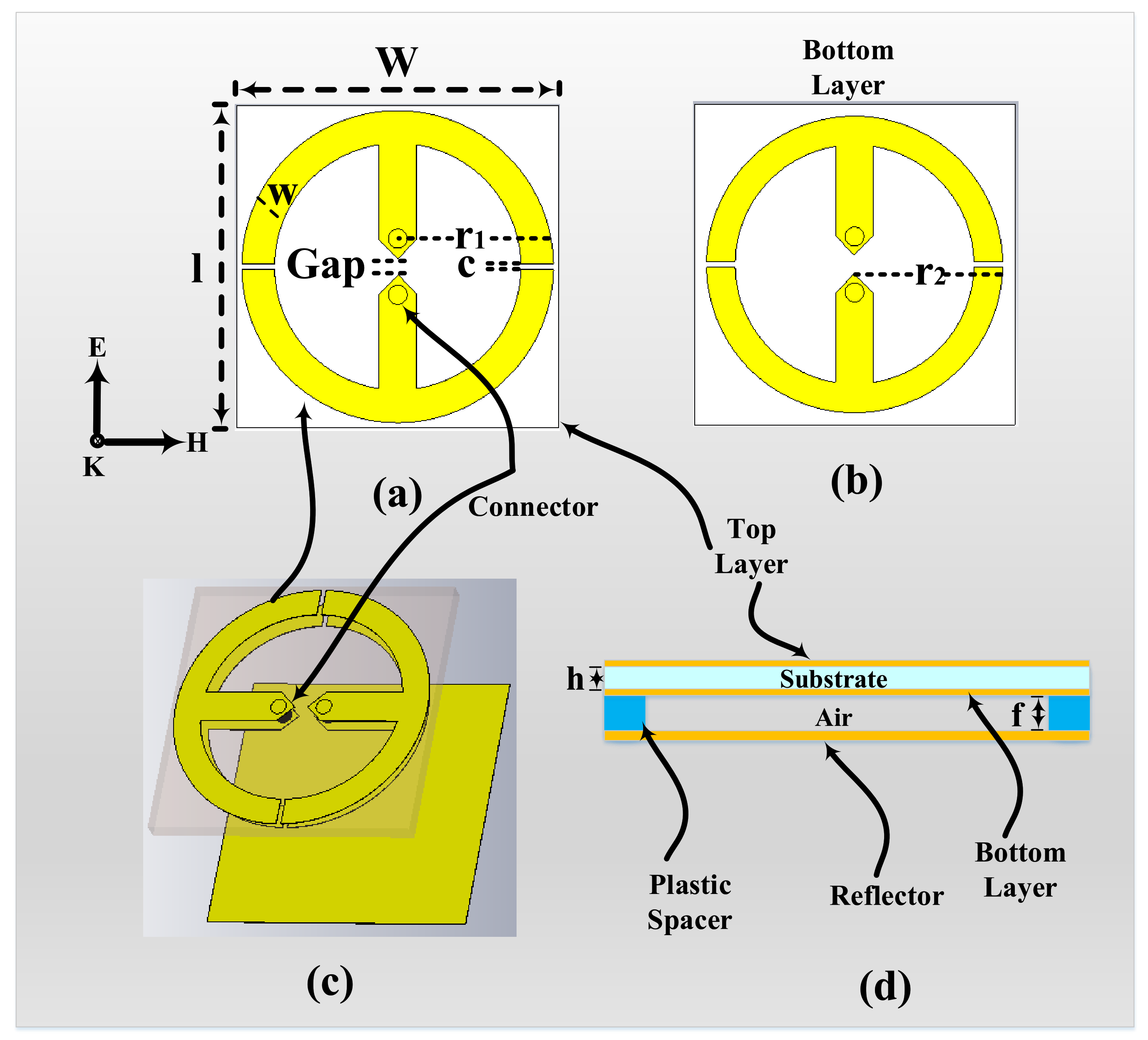
The design of the proposed dual-band unit cell is based on generating two bands from two loops printed on the top and bottom layers of a single Rogers 4003c substrate. The bottom layer is utilized instead of having the loops in the top layer only, thus miniaturizing the unit cell further. A single unit cell contains double-sided resonators where each side contains a loop with a dipole in the middle having a small gap. A resistive load R is placed on the gap of each dipole to consume the absorbed energy and to mimic a port where the rectification circuitry can be integrated, as shown in Figure 1a. The dimensions of the unit cell are w = l = 23 mm with substrate thickness h = 1.524 mm and copper thickness = 35 µm.
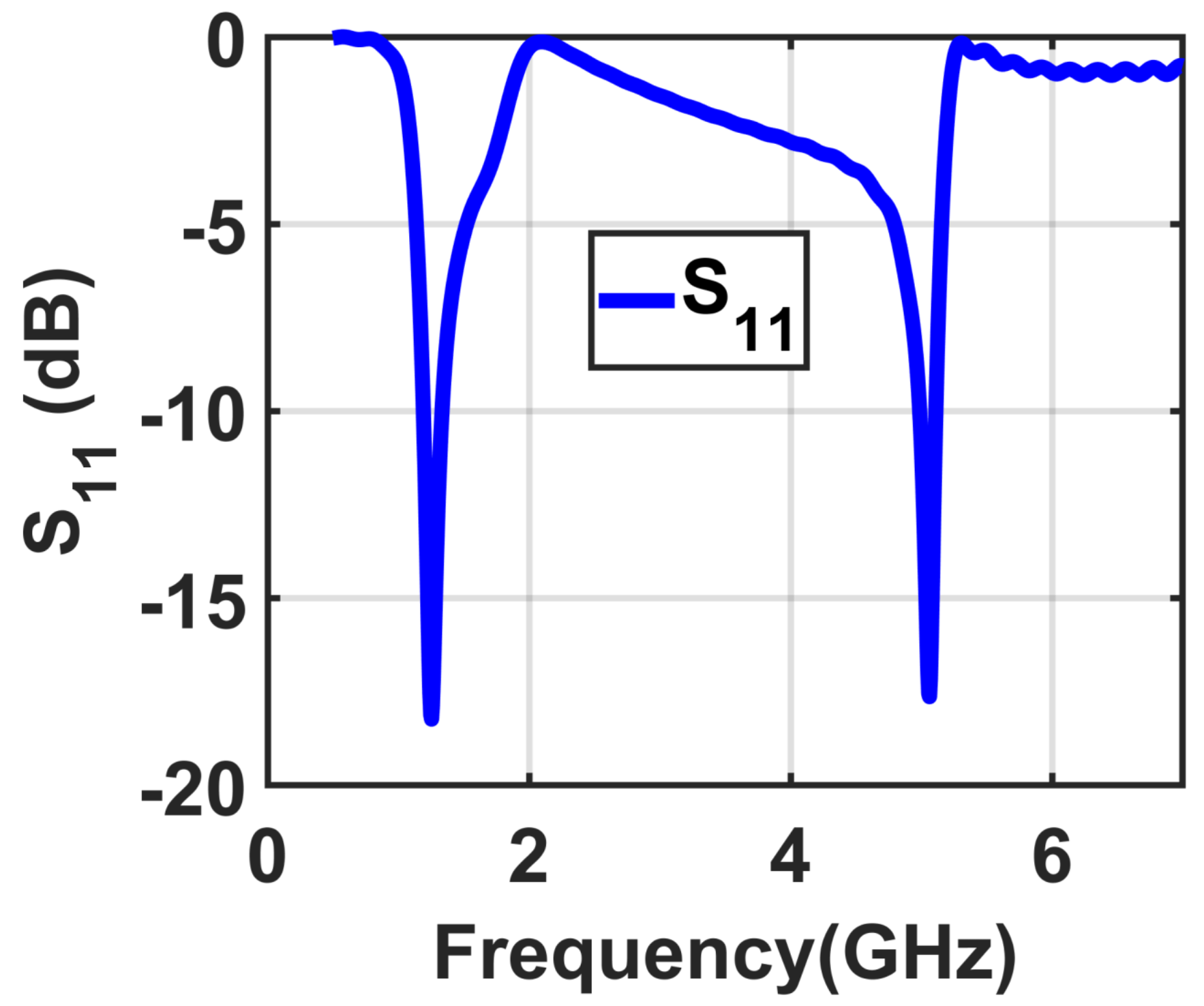
The loop on the top layer has radius r 1 = 11.2 mm, whereas the radius of the bottom loop r 2 = 10.6 mm. The two radii were carefully studied such that the results were in two frequency bands of 1.8 GHz and 5 GHz, respectively, as shown in Figure 2. Both loops on the top and bottom layers contain two cuts c that divide them into two identical half loops. Each half loop on the top and bottom layer is electrically connected from the top to the bottom layer through the substrate of the unit cell, as shown in Figure 1c. In addition, a reflector is placed at a distance f from the bottom layer, as illustrated in Figure 1d.
In the literature, the performance of the harvester is evaluated based on a higher value of the efficiency η . This value of the efficiency η is based on two main factors including the input power P i n , which is the real power available at the surface of the harvester, and the developed power P d , which can be calculated by summing all the load resistors of each unit cell. The efficiency η is then calculated by using the following equation: η = P d P i n 100 % where the developed power represents all the dissipated power across the connected loads of all unit cells within the footprint. The input power is considered as the available power on the surface area or the footprint of the harvester, which can be determined by multiplying the Poynting vector by the physical area of the harvester.
Figure 1. The presented unit cell: (a) top loop layer, (b) bottom loop layer, (c) top and bottom loop layers connected with two connectors, and (d) view of the top and bottom layers with the ground spacer reflector.
Materials 14 06242 g001
Figure 2. Simulation results of the proposed unit cell showing S 11 .
Materials 14 06242 g002
Using the CST [35] simulation setup, the main design parameters of the introduced unit cell are optimized to achieve high-efficiency collected power across the resistive load. First of all, the spacer distance f between the bottom layer and the reflector along with the resistive R load value were investigated. The f values were optimized between f = 5 mm and f = 20 mm and the R load in between R = 100 Ω and R = 350 Ω to obtain the optimum value of f with the goal of achieving a higher value of radiation to AC conversion efficiency.
Simulation results demonstrating the efficiency of the unit cell with four cases f = 5 mm, f = 10 mm, f = 15 mm, and f = 20 mm while sweeping the R load values from R = 100 Ω to R = 350 Ω are shown in Figure 3a–d, respectively. The presented unit cell collected a high efficiency of 99% at the optimum values of R = 200 Ω and f = 15 mm. Furthermore, the proposed unit cell has the capability to collect power over the entire range of R values from 100 Ω to 350 Ω , resulting in a harvester with a wide impedance bandwidth.
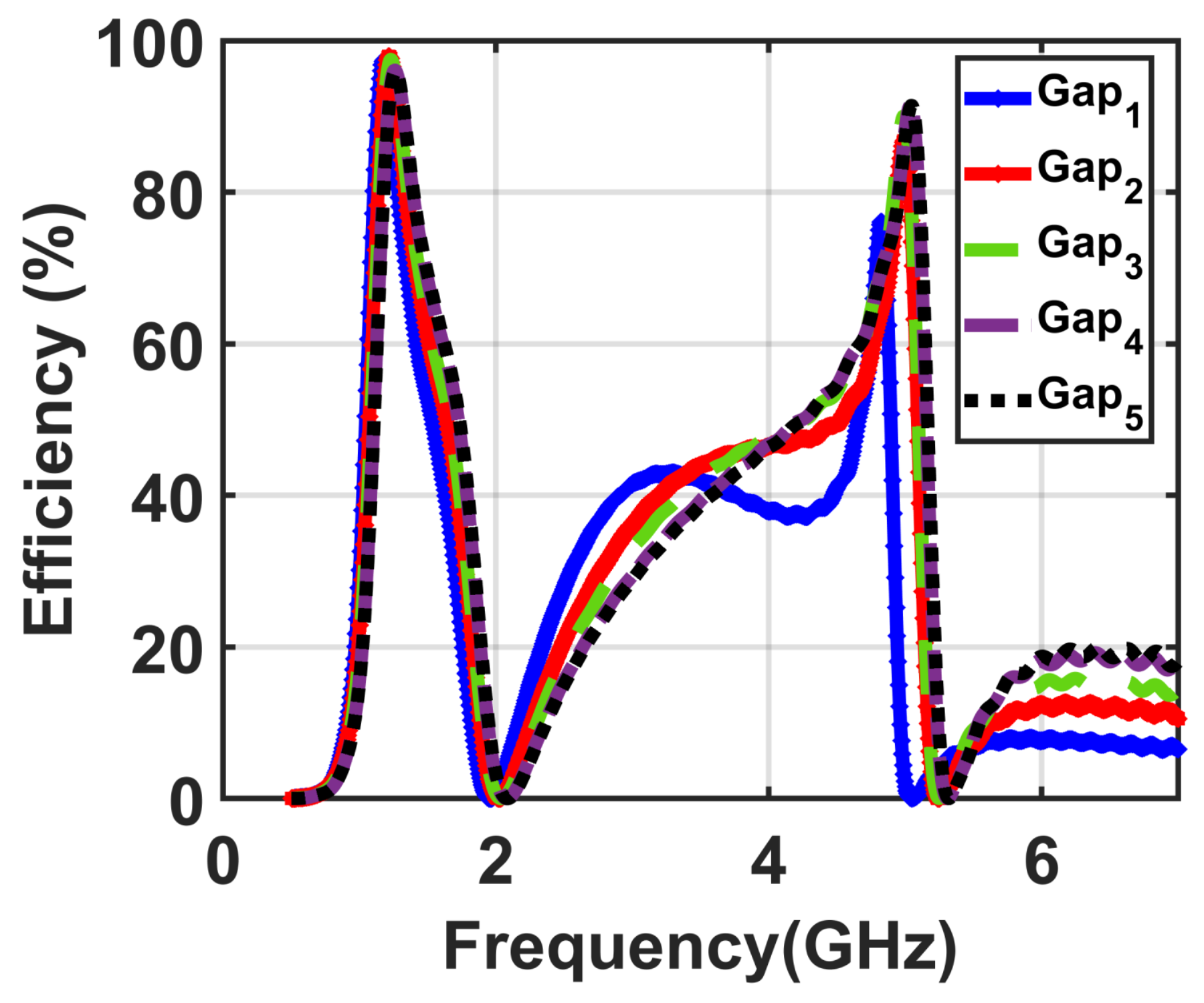
Next, three simulation environments were implemented to demonstrate the optimum values of other design parameters of the presented unit cell including the gap, cut, and width of the trace. First, a simulation was implemented to investigate the effect of different gap sizes. In this simulation environment, five different sizes of the gap were investigated for various values from G a p 1 = 0.2 mm to G a p 5 = 0.6 mm at optimum values of both the resistive load R of 200 Ω and the distance off the spacer f = 15 mm between the resonator and the reflector.
For all five values of the gap from G a p 1 = 0.2 mm to G a p 5 = 0.6 mm, the efficiency values were recorded to obtain the optimum value of the gap, which achieved higher efficiency, as illustrated in Figure 4. From the obtained results, we noticed that the optimum value of the gap was G a p 4 = 0.5 mm.
The size of the cuts c was investigated next, while all other parameters were used at the optimal values as obtained above. To show this, a simulation environment was setup for five different values of the cuts, which changed from C 1 = 0.2 mm to C 5 = 0.5 mm with the optimal values of R = 200 Ω , f = 15 mm, and G a p 4 = 0.5 mm. From the demonstrated results in Figure 5, C 3 = 0.4 mm is the optimum value to obtain the goal of higher efficiency.
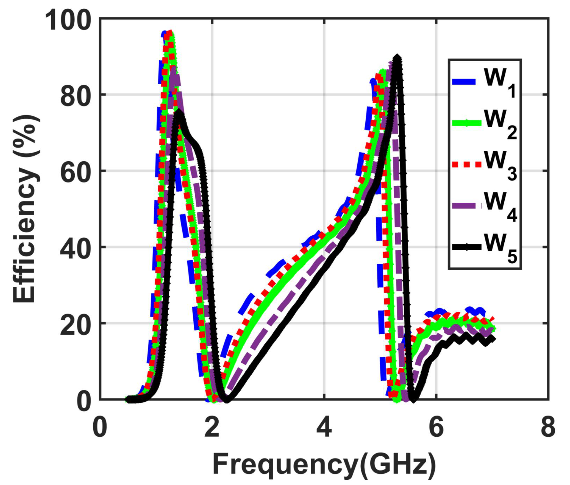
The last numerical study was performed using five different values of the width ranging from W 1 = 1.5 mm to W 5 = 3 mm at optimal values of R = 200 Ω , f = 15 mm, G a p 4 = 0.5 mm, and cut C 3 = 0.4 mm. Figure 6 shows that a width size of W 3 = 2.5 mm is the best value among the obtained results of the five investigated cases of the width from w 1 = 1.5 mm to w 5 = 3.5 mm, having the highest efficiency value.

3. The 2 × 2 Supercell Design Methodology

To demonstrate the dual-polarized feature of the presented cell, a supercell comprised of 2 × 2 unit cells was implemented. Each bottom and top layer contained four unit cells. The top left and the bottom right cells were designed for y polarizations ( R y ), and the top right and bottom left cells were designed for x polarizations ( R x ), as shown in Figure 7.
The design parameters of the 2 × 2 supercell including the resistive loads and the separation between adjacent cells s e p were simulated and optimized to achieve high collecting efficiency.
First, a numerical simulation was performed for different loads R x = R y values from 100 Ω to 350 Ω at the optimum parameters obtained for the single unit cell. Figure 8 shows the numerical efficiency results of the proposed dual-band and dual-polarized 2 × 2 supercell with different values of the terminated loads ranging from 100 Ω to 350 Ω .
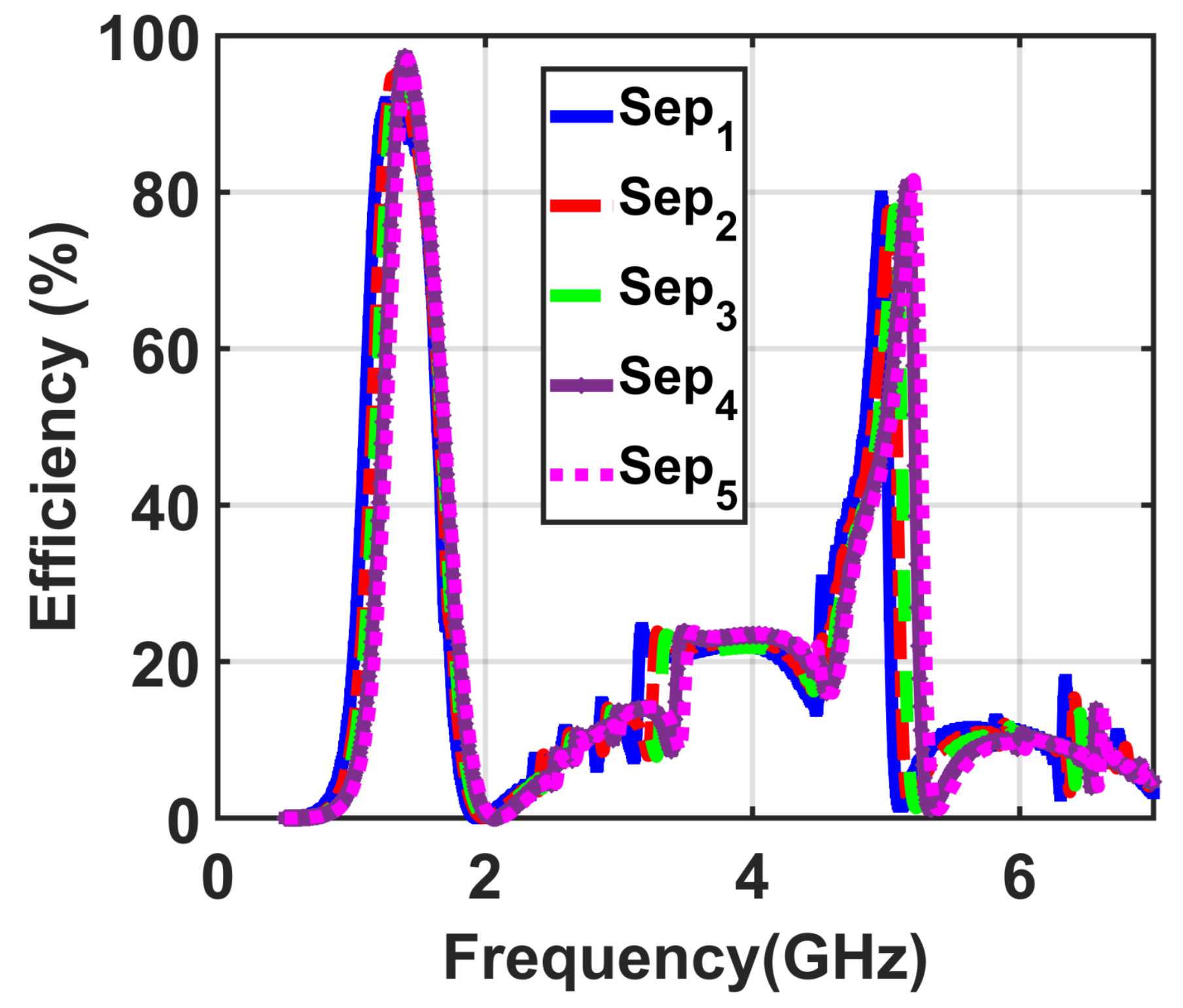
The next simulation was implemented to optimize the second design parameter of the proposed supercell including the separation between adjacent cells s e p . The values of s e p were optimized with the goal of having higher conversion efficiency. Figure 9 shows the efficiency results of the presented supercell with different values of s e p ranging from S e p 1 = 0.2 mm to S e p 5 = 0.6 mm. The results showed that the optimum value of S e p 4 achieves the highest conversion efficiency when the length is 0.4 mm.
To study the capability of the supercell to absorb electromagnetic energy with dual-polarization, a simulation was conducted for two normal incidence TE and TM mode polarizations. At the two bands of 1.9 GHz and 6.5 GHz, the efficiency is 98 % and 80 % for both TE and TM mode polarizations, respectively, as illustrated in Figure 10.
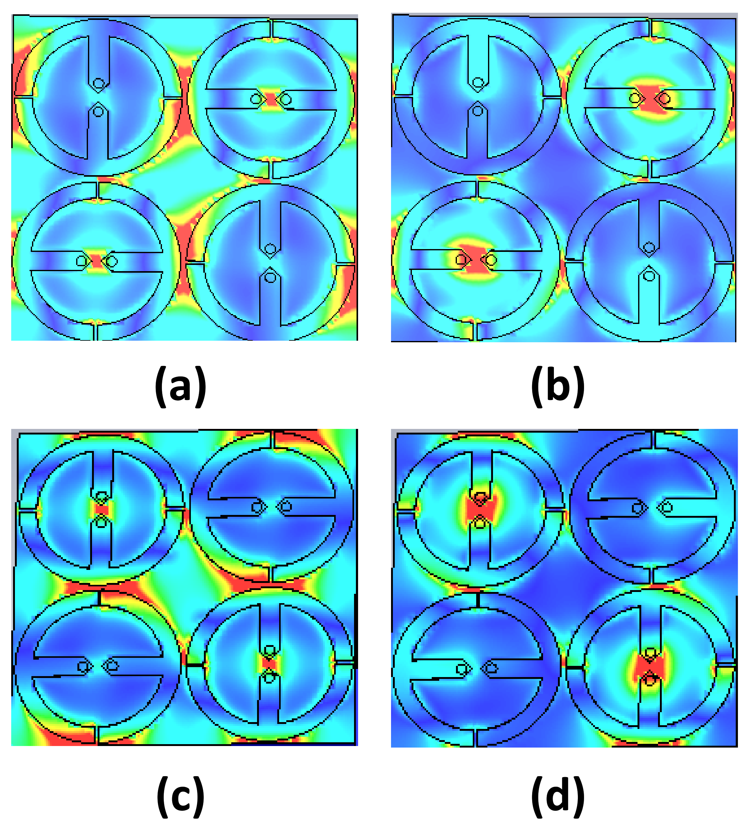
To illustrate the duality of the polarization of the implemented supercell for both bands, a simulation environment was implemented for both TE and TM polarizations. Figure 11 illustrates the obtained results of the electric field across the surface of the supercell for two polarizations, where the red colour demonstrates the high-magnitude values of the electric field for both TE and TM modes.

4. The 8 × 8 Array Metasurface Design Methodology

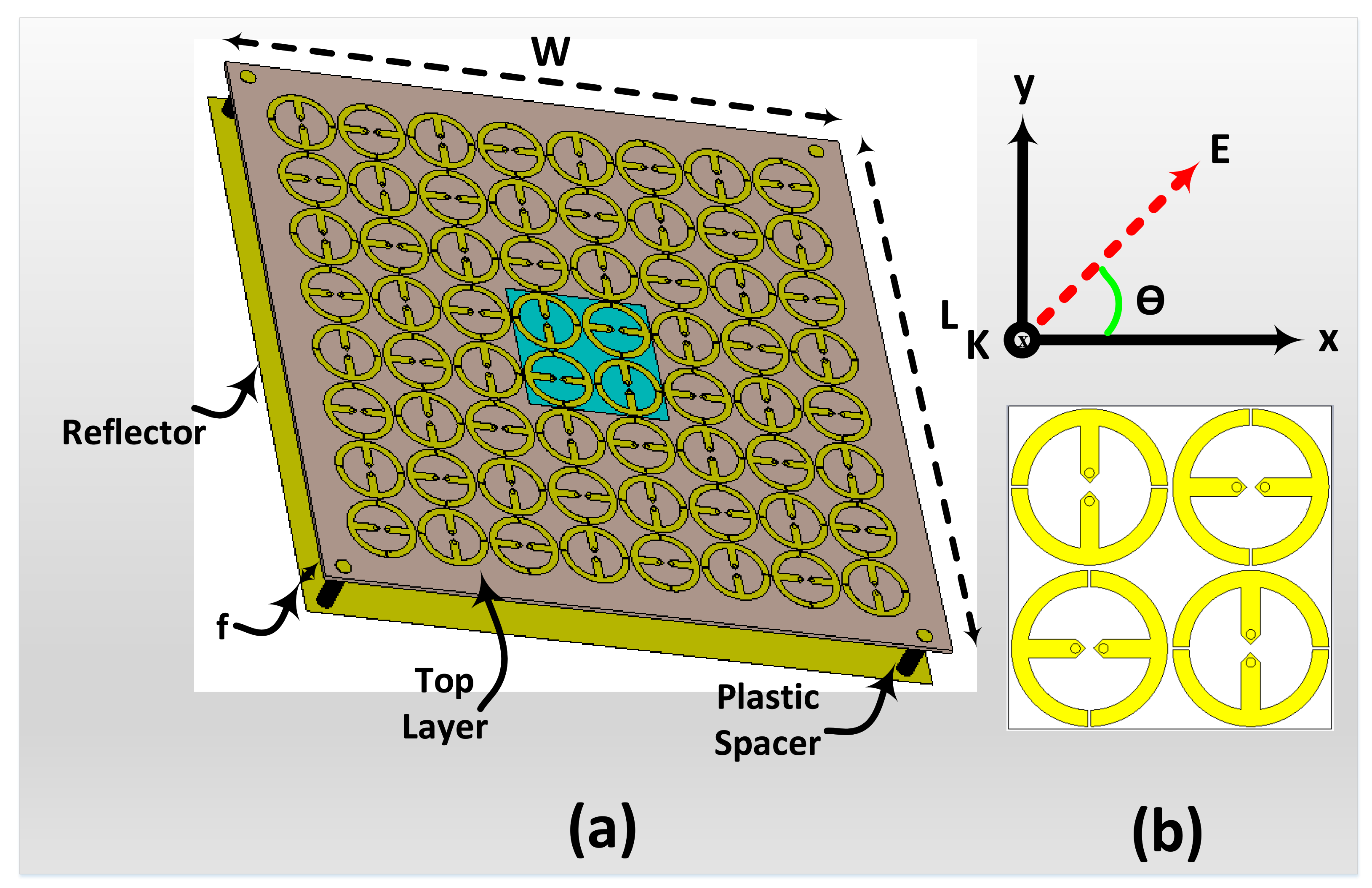
The proposed metasurface harvester comprised 8 × 8 identical unit cells, as shown in Figure 12. The overall array size of the periodic array structure is 200 mm × W = 200 mm. In the simulation environment setup, each unit cell in the proposed harvester was terminated by the optimum R of 200 Ω .
In the simulation environment, the presented metasurface was simulated as a harvester in receiving mode to collect the power from different angles of incidence using a plane wave excitation, as demonstrated in Figure 12b.
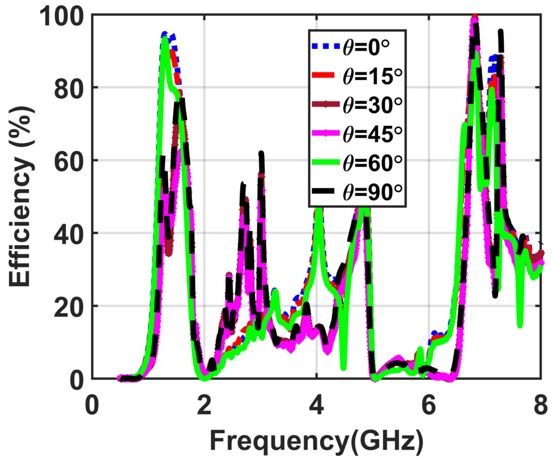
In the simulation setup, the incident wave was used with different values of the incident angle ( θ from 0 to 90 ) to study the ability of the proposed metasurface to collect the available power from different incident angles, as shown in Figure 12b. Figure 13 demonstrates the efficiency results of the proposed metasurface for various incident angles ( θ ).
The results showed that for all the incident angles of the plane wave, the efficiency of the metasurface array is 98% and 95% at both bands of operating frequencies. Figure 13 shows the overlapping curves of the efficiencies, indicating the ability of the introduced metasurface to harvest the incident electromagnetic waves from different angles of incidence equally.
To demonstrate the novelty of the proposed dual-band and polarization-independent metasurface, Table 1 shows the advantages of the proposed metasurface array presented in this paper compared with a number of state-of-the-art dual-band and dual-polarized arrays that are based on metasurfaces presented in the literature. The proposed metasurface design allows for a simple connection of tightly placed unit cells where integrating a matching network has two main advantages compared with other developed metasurface arrays presented in the literature. The first feature of the proposed metasurface is the wideband matching impedance. Such an impedance bandwidth is defined as the range of impedances that results in a harvesting efficiency of 75% or higher. From the results presented in Figure 3, a wide range of impedances from 50 Ω to 350 Ω resulted in efficiencies of at least 75%. Another advantage of the proposed metasurface is that such a wideband impedance response allows for the possibility of integrating a wide range of diodes without the need for a matching network between the diode and the electromagnetic collector.

5. Conclusions

The novel design of a planar, simple, multipolarized, and dual-band metasurface was presented. The proposed metasurface was constructed from 8 × 8 unit cells, which provide high efficiencies at various incident angles with various terminated load values. The novelty of the presented metasurface for energy harvesting was demonstrated through several numerical studies, which showed the ability of the proposed metasurface to achieve a higher efficiency of 98% and 95% for two operating frequency of 1.8 and 6.5 GHz with a multipolarized incident wave.

Author Contributions

Conceptualization, M.A.A. and T.S.A.; methodology, M.A.A. and T.S.A.; Simulation and software analysis, M.A.A. and T.S.A.; investigation the proposed idea, M.A.A. and T.S.A.; writing—original draft preparation, M.A.A. and T.S.A.; writing—review and editing, M.A.A. and T.S.A.; visualization, M.A.A. and T.S.A.; supervision, T.S.A.; project administration, T.S.A.; funding acquisition, T.S.A. All authors have read and agreed to the published version of the manuscript.

Funding

This project is supported by the Deputyship for Research & Innovation, Ministry of Education in Saudi Arabia under project number 785. The project is also supported partially by the Deanship of Scientific Research at Prince Sattam bin Abdulaziz University, Alkharj, Saudi Arabia.

Institutional Review Board Statement

Not applicable.

Informed Consent Statement

Not applicable.

Data Availability Statement

The data presented in this study are available on request from the corresponding author.

Acknowledgments

The authors extend their appreciation to the Deputyship for Research & Innovation, Ministry of Education in Saudi Arabia, for funding this research work through Project Number 785. The authors also acknowledge the support of the Deanship of Scientific Research at Prince Sattam bin Abdulaziz University, Alkharj, Saudi Arabia.

Conflicts of Interest

The authors declare no conflict of interest.

References

  1. Amer, A.A.G.; Sapuan, S.Z.; Nasimuddin, N.; Alphones, A.; Zinal, N.B. A Comprehensive Review of Metasurface Structures Suitable for RF Energy Harvesting. IEEE Access 2020, 8, 76433–76452. [Google Scholar] [CrossRef]
  2. Bakkali, A.; Pelegrí-Sebastiá, J.; Sogorb, T.; Llario, V.; Bou-Escriva, A. A dual-band antenna for RF energy harvesting systems in wireless sensor networks. J. Sens. 2016, 2016. [Google Scholar] [CrossRef] [Green Version]
  3. Olgun, U.; Chen, C.C.; Volakis, J.L. Wireless power harvesting with planar rectennas for 2.45 GHz RFIDs. In Proceedings of the 2010 URSI International Symposium on Electromagnetic Theory, Berlin, Germany, 16–19 August 2010; IEEE: New York, NY, USA, 2010; pp. 329–331. [Google Scholar]
  4. Sarker, M.R.; Saad, M.H.M.; Olazagoitia, J.L.; Vinolas, J. Review of Power Converter Impact of Electromagnetic Energy Harvesting Circuits and Devices for Autonomous Sensor Applications. Electronics 2021, 10, 1108. [Google Scholar] [CrossRef]
  5. Shafique, K.; Khawaja, B.A.; Khurram, M.D.; Sibtain, S.M.; Siddiqui, Y.; Mustaqim, M.; Chattha, H.T.; Yang, X. Energy harvesting using a low-cost rectenna for Internet of Things (IoT) applications. IEEE Access 2018, 6, 30932–30941. [Google Scholar] [CrossRef]
  6. Ballo, A.; Bottaro, M.; Grasso, A.D. A Review of Power Management Integrated Circuits for Ultrasound-Based Energy Harvesting in Implantable Medical Devices. Appl. Sci. 2021, 11, 2487. [Google Scholar] [CrossRef]
  7. Awais, Q.; Jin, Y.; Chattha, H.T.; Jamil, M.; Qiang, H.; Khawaja, B.A. A compact rectenna system with high conversion efficiency for wireless energy harvesting. IEEE Access 2018, 6, 35857–35866. [Google Scholar] [CrossRef]
  8. Chen, Y.S.; Lai, F.P.; You, J.W. Analysis of antenna radiation characteristics using a hybrid ray tracing algorithm for indoor WiFi energy-harvesting rectennas. IEEE Access 2019, 7, 38833–38846. [Google Scholar] [CrossRef]
  9. Sun, H.; He, H.; Huang, J. Polarization-Insensitive Rectenna Arrays With Different Power Combining Strategies. IEEE Antennas Wirel. Propag. Lett. 2020, 19, 492–496. [Google Scholar] [CrossRef]
  10. Chai, J.; Cheng, J.; Zhang, D.; Xiong, Y.; Yang, X.; Ba, X.; Ullah, S.; Zheng, G.; Yan, M.; Cao, M. Enhancing electromagnetic wave absorption performance of Co3O4 nanoparticles functionalized MoS2 nanosheets. J. Alloy. Compd. 2020, 829, 154531. [Google Scholar] [CrossRef]
  11. Zhang, D.; Zhang, H.; Cheng, J.; Raza, H.; Liu, T.; Liu, B.; Ba, X.; Zheng, G.; Chen, G.; Cao, M. Customizing coaxial stacking VS 2 nanosheets for dual-band microwave absorption with superior performance in the C-and K u-bands. J. Mater. Chem. C 2020, 8, 5923–5933. [Google Scholar] [CrossRef]
  12. Alavikia, B.; Almoneef, T.S.; Ramahi, O.M. Complementary split ring resonator arrays for electromagnetic energy harvesting. Appl. Phys. Lett. 2015, 107, 033902. [Google Scholar] [CrossRef] [Green Version]
  13. Costanzo, S.; Venneri, F. Polarization-Insensitive Fractal Metamaterial Surface for Energy Harvesting in IoT Applications. Electronics 2020, 9, 959. [Google Scholar] [CrossRef]
  14. Zhang, X.; Li, L. A dual-band polarization-independent and wide-angle metasurface for electromagnetic power harvesting. In Proceedings of the 2017 Sixth Asia-Pacific Conference on Antennas and Propagation (APCAP), Xi’an, China, 16–19 October 2017; IEEE: New York, NY, USA, 2017; pp. 1–3. [Google Scholar]
  15. Li, L.; Zhang, X.; Song, C.; Huang, Y. Progress, challenges, and perspective on metasurfaces for ambient radio frequency energy harvesting. Appl. Phys. Lett. 2020, 116, 060501. [Google Scholar] [CrossRef]
  16. Aldhaeebi, M.A.; Almoneef, T.S. Planar Dual Polarized Metasurface Array for Microwave Energy Harvesting. Electronics 2020, 9, 1985. [Google Scholar] [CrossRef]
  17. Younesiraad, H.; Niksan, O.; Bemani, M. Highly-Efficient Double-Sided Dual-Band Polarization-Independent Metasurface Energy Harvester. In Proceedings of the 2020 28th Iranian Conference on Electrical Engineering (ICEE), Tabriz, Iran, 4–6 August 2020; IEEE: New York, NY, USA, 2020; pp. 1–4. [Google Scholar]
  18. Ayop, O.; Rahim, M.K.A.; Murad, N.A.; Samsuri, N.A. Double Layer Polarization Insensitive Metamaterial Absorber with Dual Resonances. In Theory and Applications of Applied Electromagnetics; Springer: Berlin/Heidelberg, Germany, 2015; pp. 231–238. [Google Scholar]
  19. Ghaderi, B.; Nayyeri, V.; Soleimani, M.; Ramahi, O.M. Pixelated metasurface for dual-band and multi-polarization electromagnetic energy harvesting. Sci. Rep. 2018, 8, 13227. [Google Scholar] [CrossRef]
  20. Almoneef, T.S.; Erkmen, F.; Ramahi, O.M. Harvesting the energy of multi-polarized electromagnetic waves. Sci. Rep. 2017, 7, 14656. [Google Scholar] [CrossRef] [Green Version]
  21. Yu, F.; Du, J.; Yang, X. Four-Band Polarization-Insensitive and Wide-Angle Metasurface with Simplified Structure for Harvesting Electromagnetic Energy. In Proceedings of the 2019 IEEE MTT-S International Wireless Symposium (IWS), Guangzhou, China, 19–22 May 2019; IEEE: New York, NY, USA, 2019; pp. 1–3. [Google Scholar]
  22. El Badawe, M.; Ramahi, O. Polarization independent metasurface energy harvester. In Proceedings of the 2016 IEEE 17th Annual Wireless and Microwave Technology Conference (WAMICON), Clearwater, FL, USA, 27–28 April 2016; IEEE: New York, NY, USA, 2016; pp. 1–3. [Google Scholar]
  23. Yu, F.; Yang, X.; Zhong, H.; Chu, C.; Gao, S. Polarization-insensitive wide-angle-reception metasurface with simplified structure for harvesting electromagnetic energy. Appl. Phys. Lett. 2018, 113, 123903. [Google Scholar] [CrossRef] [Green Version]
  24. Ashoor, A.Z.; Ramahi, O.M. Polarization-independent cross-dipole energy harvesting surface. IEEE Trans. Microw. Theory Tech. 2019, 67, 1130–1137. [Google Scholar] [CrossRef]
  25. Zhong, H.T.; Yang, X.X.; Song, X.T.; Guo, Z.Y.; Yu, F. Wideband metamaterial array with polarization-independent and wide incident angle for harvesting ambient electromagnetic energy and wireless power transfer. Appl. Phys. Lett. 2017, 111, 213902. [Google Scholar] [CrossRef]
  26. Xu, P.; Jiang, W.X. Dual-polarization metasurface for microwave energy harvesting. In Proceedings of the 2019 IEEE Asia-Pacific Microwave Conference (APMC), Singapore, 10–13 December 2019; IEEE: New York, NY, USA, 2019; pp. 989–990. [Google Scholar]
  27. Erkmen, F.; Ramahi, O.M. A Dual-band Electromagnetic Energy Harvesting Surface. In Proceedings of the 2019 IEEE International Symposium on Antennas and Propagation and USNC-URSI Radio Science Meeting, Atlanta, GA, USA, 7–12 July 2019; IEEE: New York, NY, USA, 2019; pp. 1157–1158. [Google Scholar]
  28. Chandrasekaran, K.T.; Agarwal, K.; Alphones, A.; Mittra, R.; Karim, M.F. Compact Dual-Band Metamaterial-Based High-Efficiency Rectenna: An Application for Ambient Electromagnetic Energy Harvesting. IEEE Antennas Propag. Mag. 2020, 62, 18–29. [Google Scholar] [CrossRef]
  29. Wang, X.; Zhao, Z.; Chen, K.; He, F.; Yuan, L.; Lu, T. Numerical studies on dual-band electromagnetic energy harvesting with double-ring split-ring resonators. In Proceedings of the 2015 50th International Universities Power Engineering Conference (UPEC), Stoke-on-Trent, UK, 1–4 September 2015; IEEE: New York, NY, USA, 2015; pp. 1–5. [Google Scholar]
  30. Mahfoudi, H.; Takhedmit, H.; Tellache, M. Dual-Band Dual-Polarized Stacked Rectenna for RF Energy Harvesting at 1.85 and 2.45 GHz. In Proceedings of the 12th European Conference on Antennas and Propagation (EuCAP 2018), London, UK, 9–13 April 2018; p. 4. [Google Scholar]
  31. Wang, J.; Yang, R.; Tian, J.; Chen, X.; Zhang, W. A dual-band absorber with wide-angle and polarization insensitivity. IEEE Antennas Wirel. Propag. Lett. 2018, 17, 1242–1246. [Google Scholar] [CrossRef]
  32. Ramya, S.; Srinivasa Rao, I. Design of polarization-insensitive dual-band metamaterial absorber. Prog. Electromagn. Res. 2016, 50, 23–31. [Google Scholar] [CrossRef] [Green Version]
  33. Zhang, X.; Liu, H.; Li, L. Tri-band miniaturized wide-angle and polarization-insensitive metasurface for ambient energy harvesting. Appl. Phys. Lett. 2017, 111, 071902. [Google Scholar] [CrossRef]
  34. Zhong, H.T.; Yang, X.X.; Tan, C.; Yu, K. Triple-band polarization-insensitive and wide-angle metamaterial array for electromagnetic energy harvesting. Appl. Phys. Lett. 2016, 109, 253904. [Google Scholar] [CrossRef]
  35. CST. Computer Simulation and Technology. Available online: http://www.CST.com (accessed on 7 May 2020).
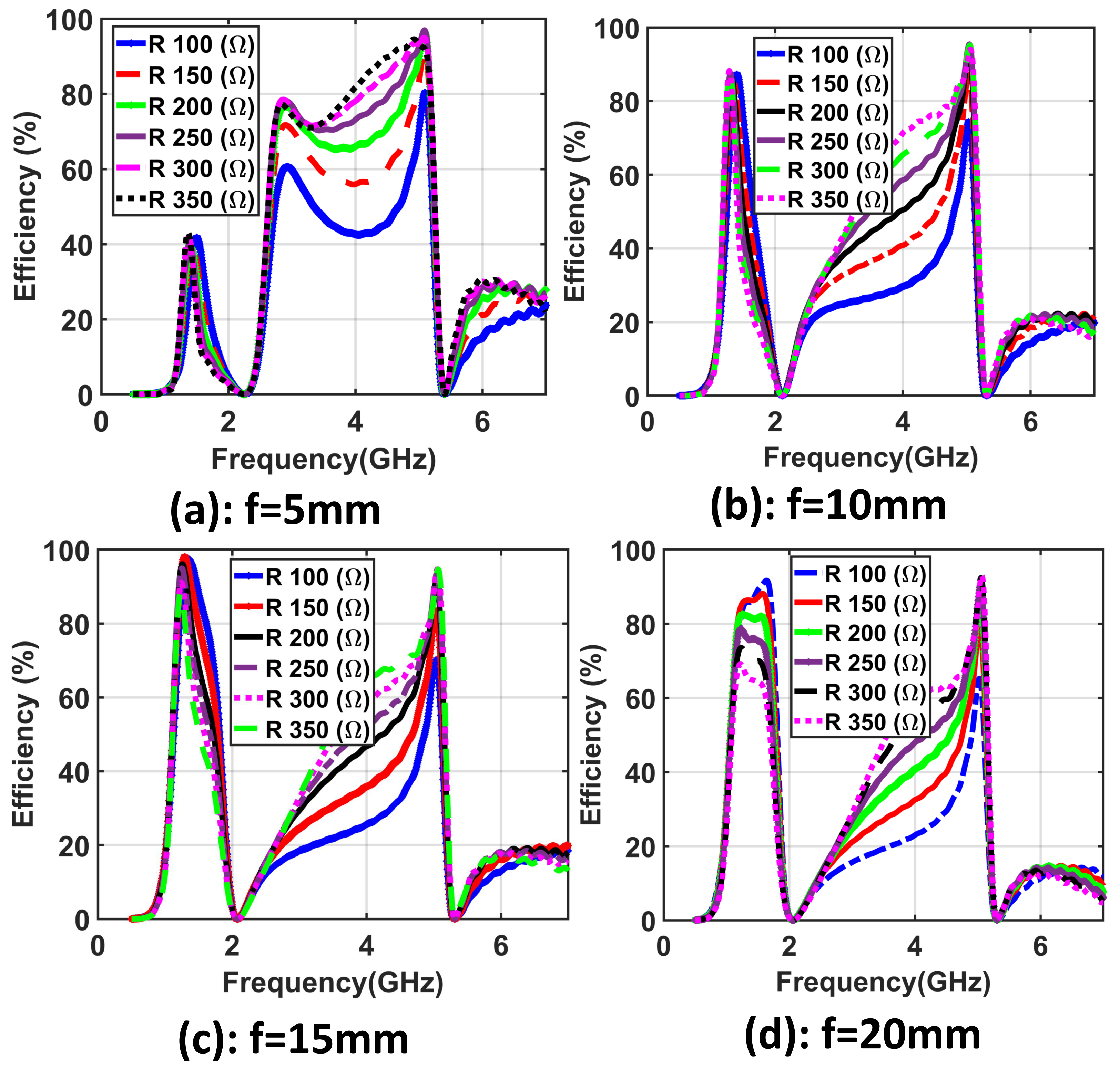
Figure 3. Results of the introduced unit cell demonstrating the efficiency using different values of the R load from 100 Ω to 350 Ω and using four cases of f: (a) f = 5 mm, (b) f = 10 mm, (c) f = 15 mm, and (d) f = 20 mm.
Materials 14 06242 g003
Figure 4. Obtained results of the efficiency of the five investigated cases for the values of the gap from G a p 1 = 0.2 mm to G a p 5 = 0.6 mm.
Materials 14 06242 g004
Figure 5. Obtained results of the efficiency of the five investigated cases for the values of the cuts from C 1 = 0.2 mm to C 5 = 0.6 mm.
Materials 14 06242 g005
Figure 6. Obtained results of the efficiency of the five investigated cases for the values of the width from W 1 = 1.5 mm to W 5 = 3.5 mm.
Materials 14 06242 g006
Figure 7. Geometry of the introduced supercell: (a) top loop layer and (b) view of the multiple polarizations at different angles of the incident power.
Materials 14 06242 g007
Figure 8. The obtained results demonstrating the efficiency of the presented supercell with different values of R ranging from 100 Ω to 350 Ω .
Materials 14 06242 g008
Figure 9. Obtained results demonstrating the efficiency with the separation between adjacent cells of the implemented supercell varied.
Materials 14 06242 g009
Figure 10. Obtained results illustrating the efficiency of the implemented supercell for both TE and TM modes.
Materials 14 06242 g010
Figure 11. Obtained results of the implemented supercell illustrating the magnitude of the E-field across the surface of the proposed super unit cell by the red colour for (a) TE mode (Polarization 1) at 1.9 GHz, (b) TE mode (Polarization 1) at 5 GHz, (c) TM mode (Polarization 2) at 1.9 GHz, and (d) TM mode (Polarization 2) at 5 GHz.
Materials 14 06242 g011
Figure 12. (a) Geometry of the implemented 8 × 8 metasurface, (b) available power from different incident angles.
Materials 14 06242 g012
Figure 13. Obtained results demonstrating the efficiency with various incident angles of the implemented 8 × 8 metasurface.
Materials 14 06242 g013
Table 1. A comparative study of the proposed dual-band and polarization-independent metasurface array with various state-of-the-art published papers.
ReferenceFrequency
Bands (GHz)
Unit Cell
Size
Bandwidth of
Matching Impedance
Need for Matching
Network
Efficiency
%
[17]5.5 and 7.2 0.22 λ NarrowbandYes94 and 93%
[19]2.45 and 6 0.23 λ NarrowbandYes90 and 85%
[30]1.85 and 2.45 0.32 λ NarrowbandYes47and 23 %
[31]2.7 and 5 0.31 λ NarrowbandYes91 and 84 %
[32]1.68 and 2.12 0.67 λ NarrowbandYes67 and 36 %
This work1.8 and 6.5 0.25 λ WidebandNO98 and 95%
Publisher’s Note: MDPI stays neutral with regard to jurisdictional claims in published maps and institutional affiliations.