
Structural Integrity Assessment of Composites Plates with Embedded PZT Transducers for Structural Health Monitoring


Abstract
:1. Introduction
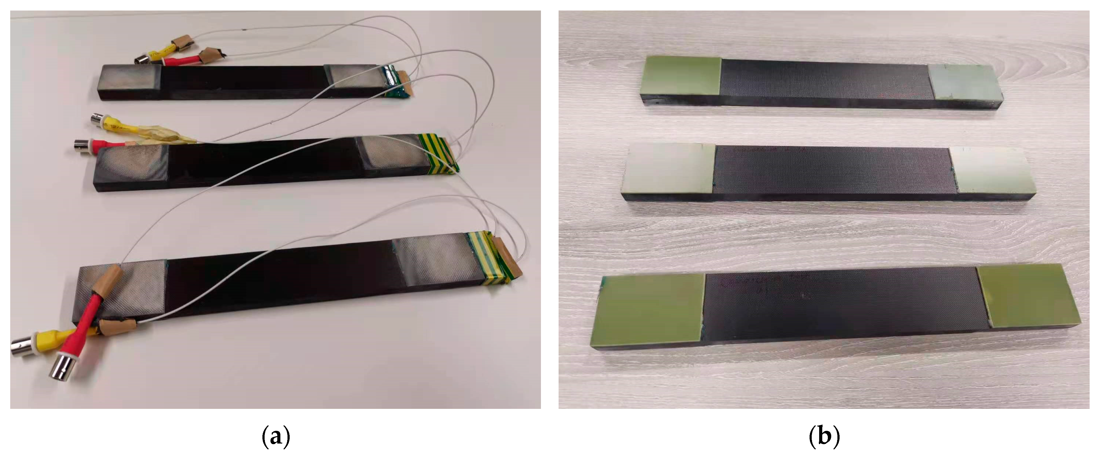
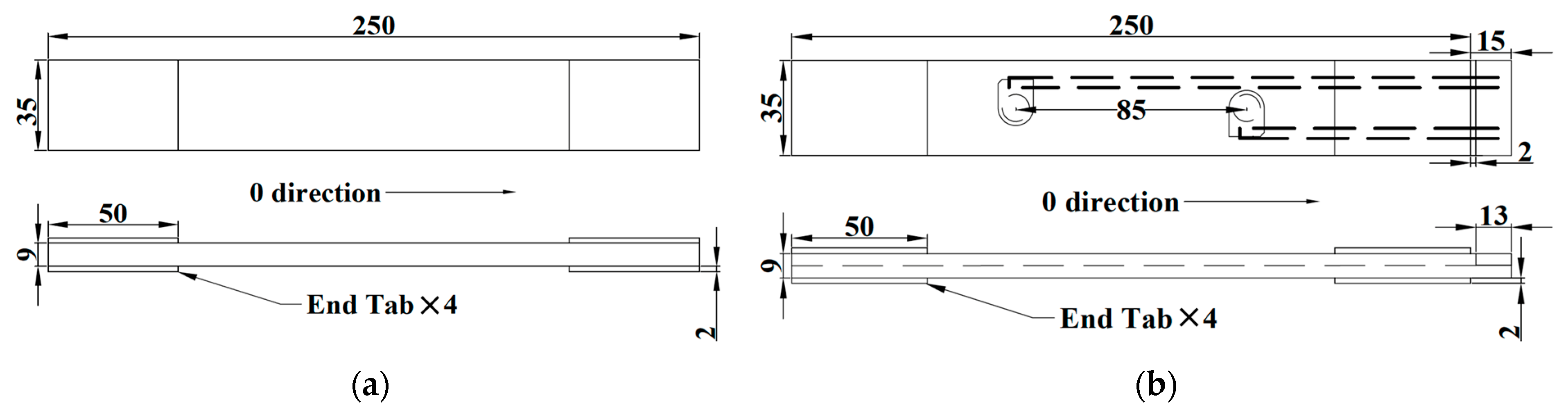
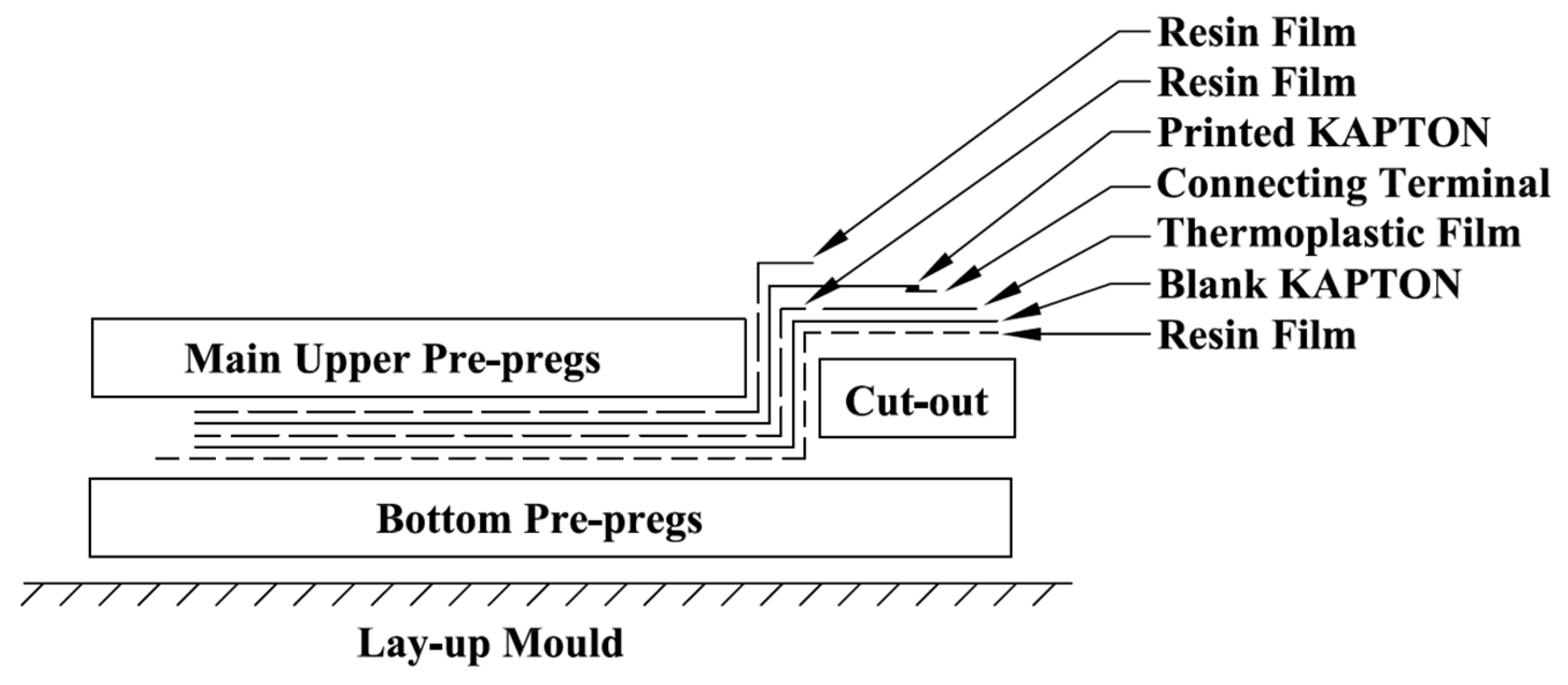
2. Manufacturing
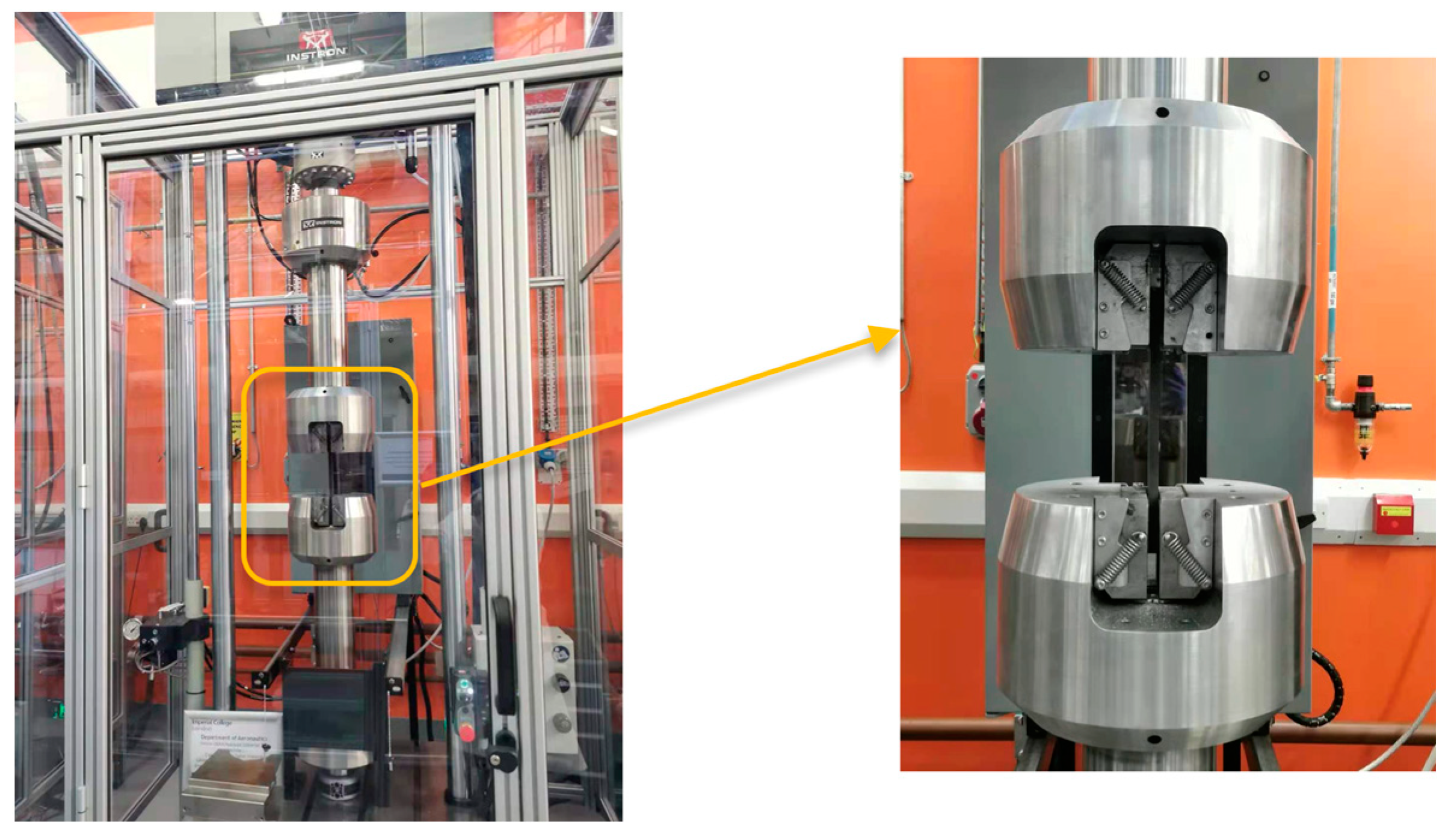
3. Fatigue Tests
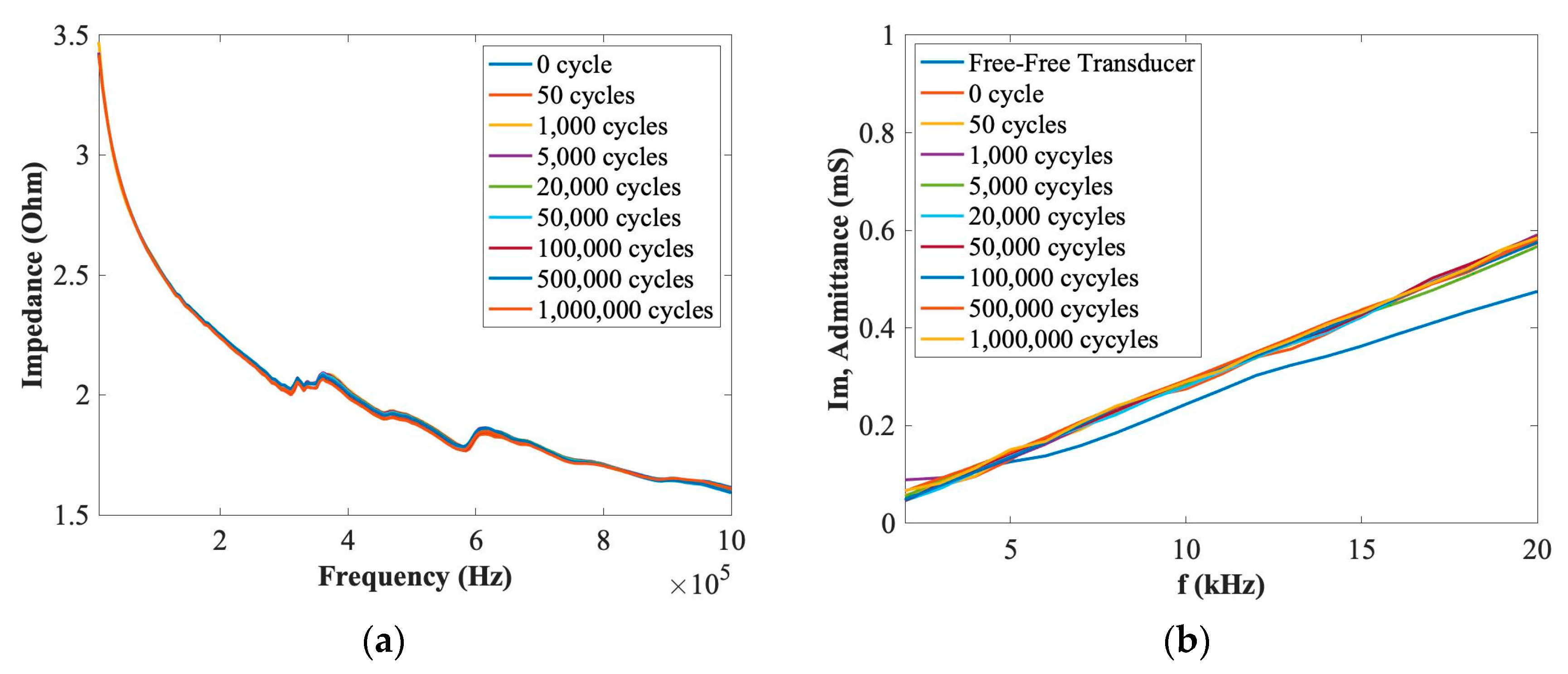
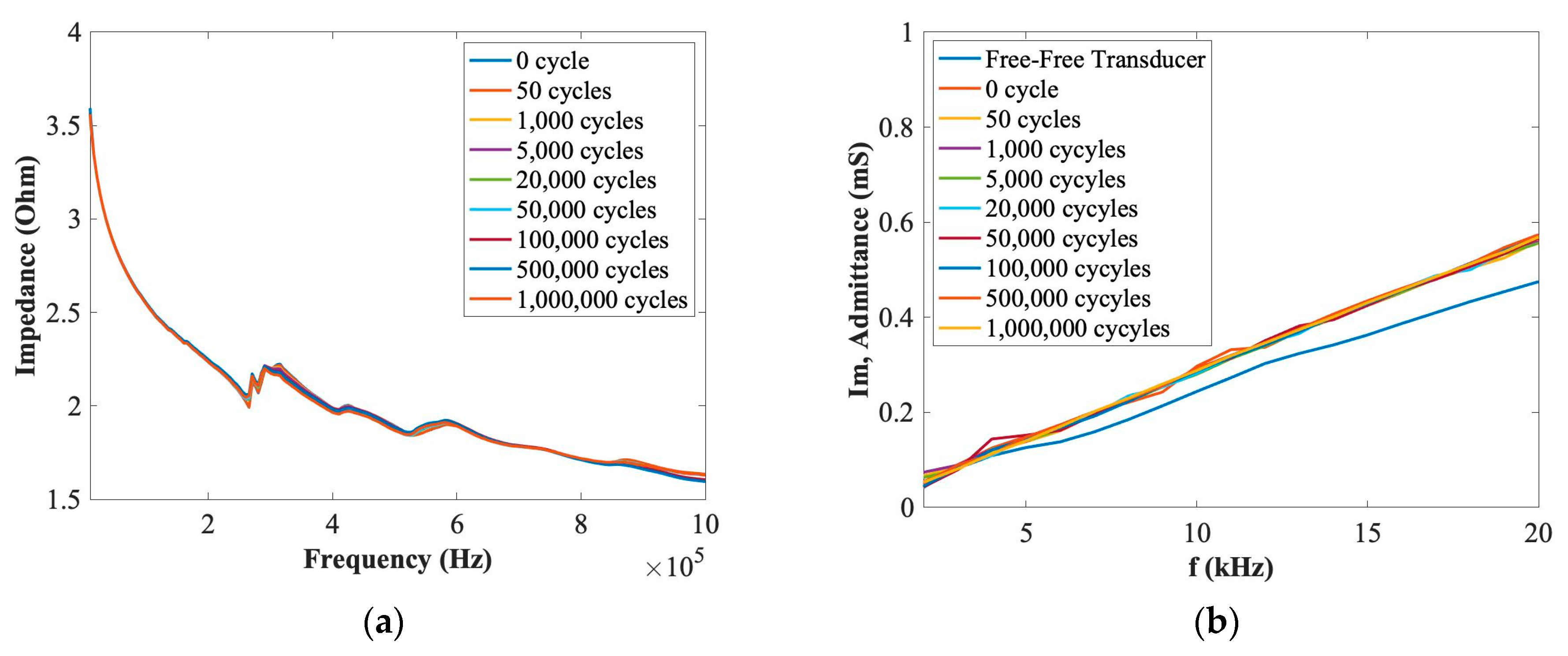
3.1. Electro-Mechanical Impedance (EMI) Properties
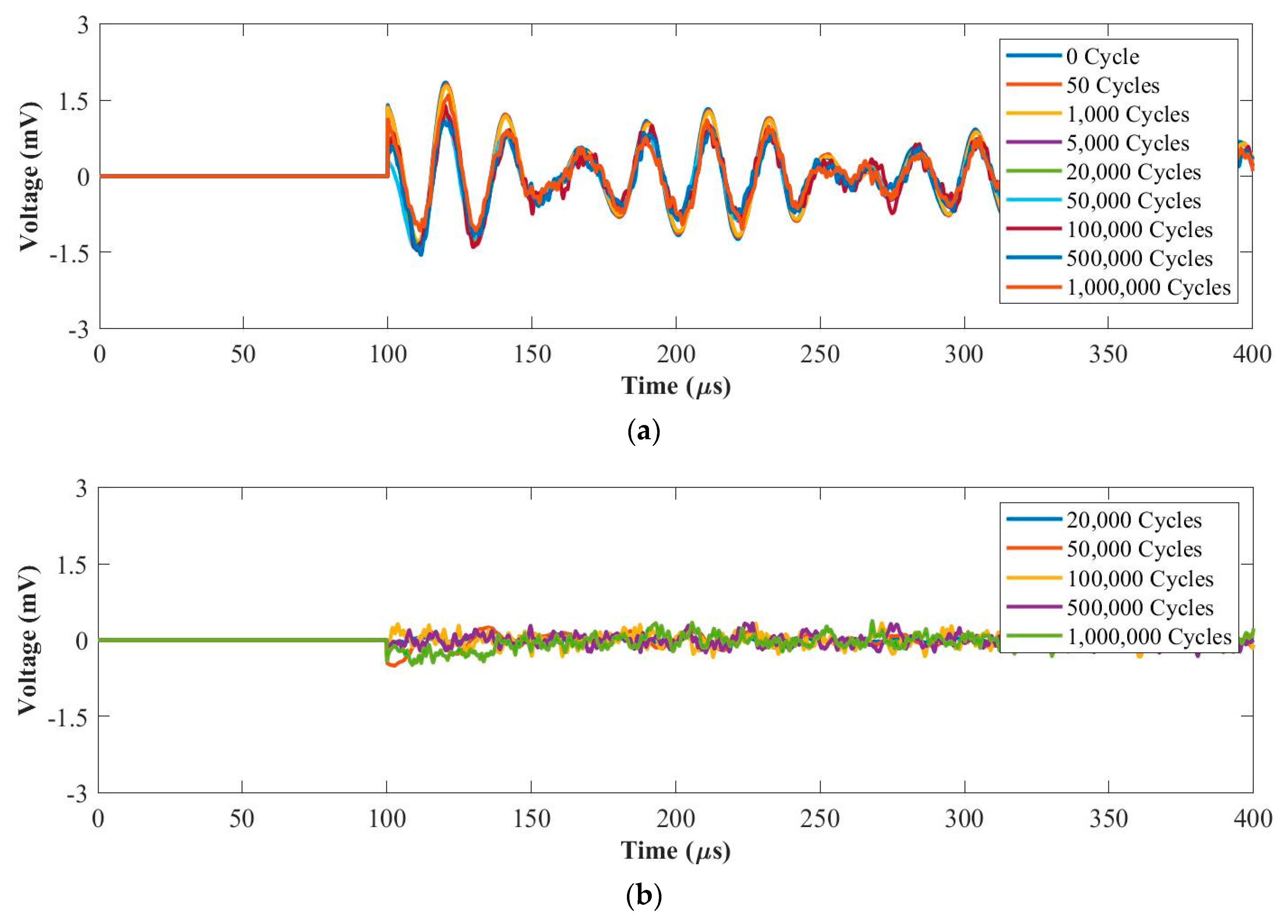
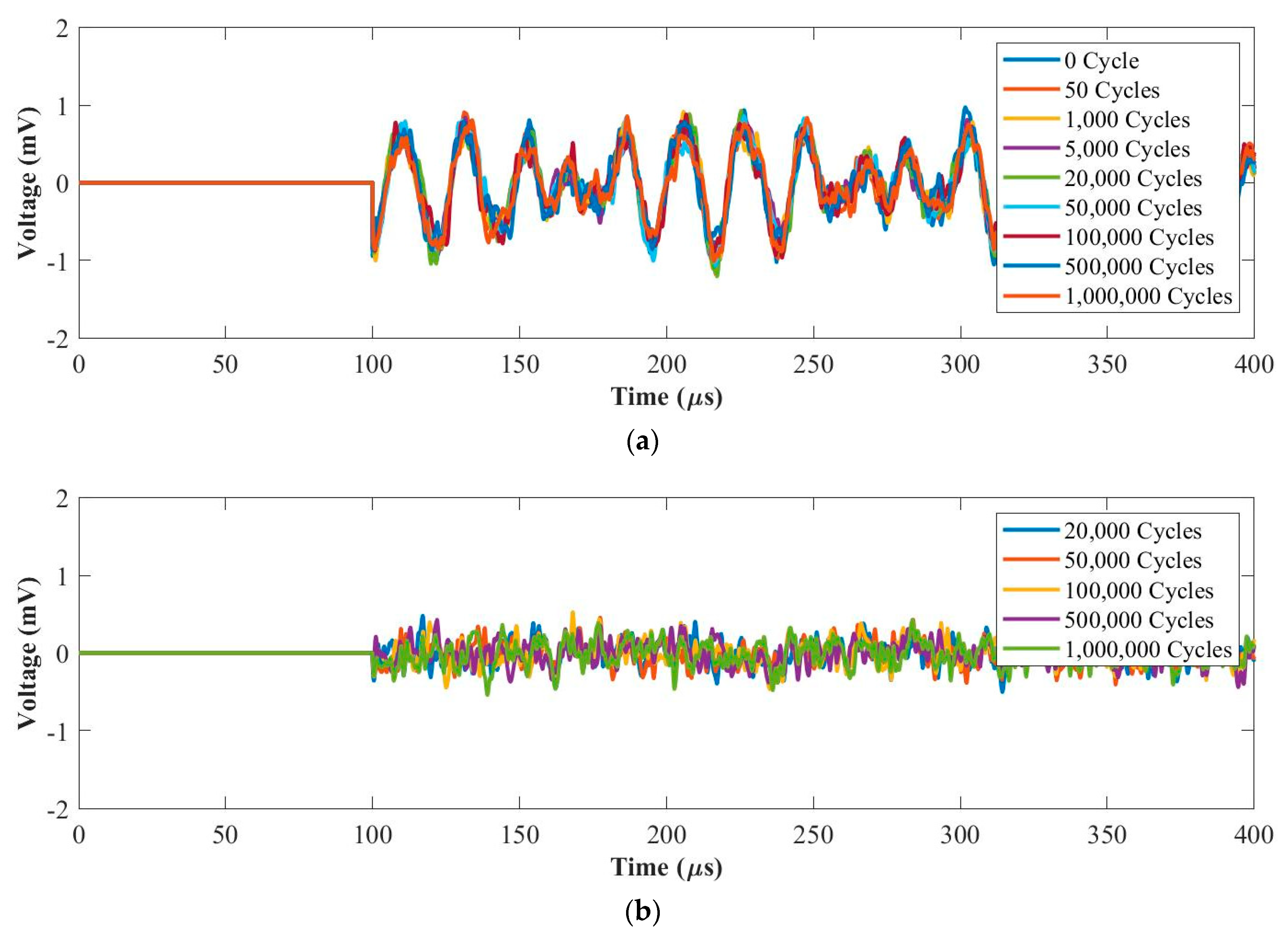
3.2. Sensing Performance of PZT Transducers
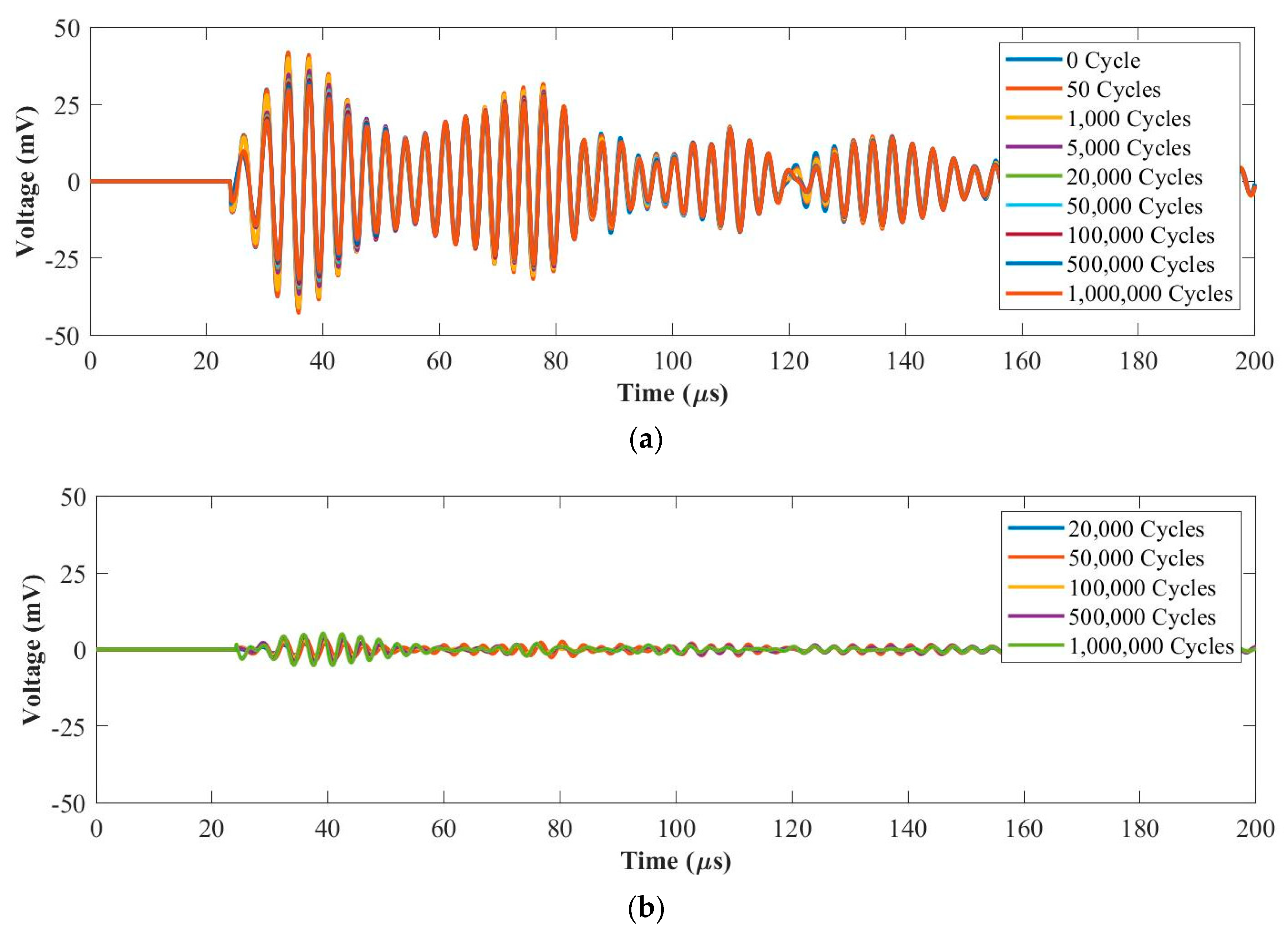
3.2.1. Fatigue Force Range 1: 0.5~5 kN
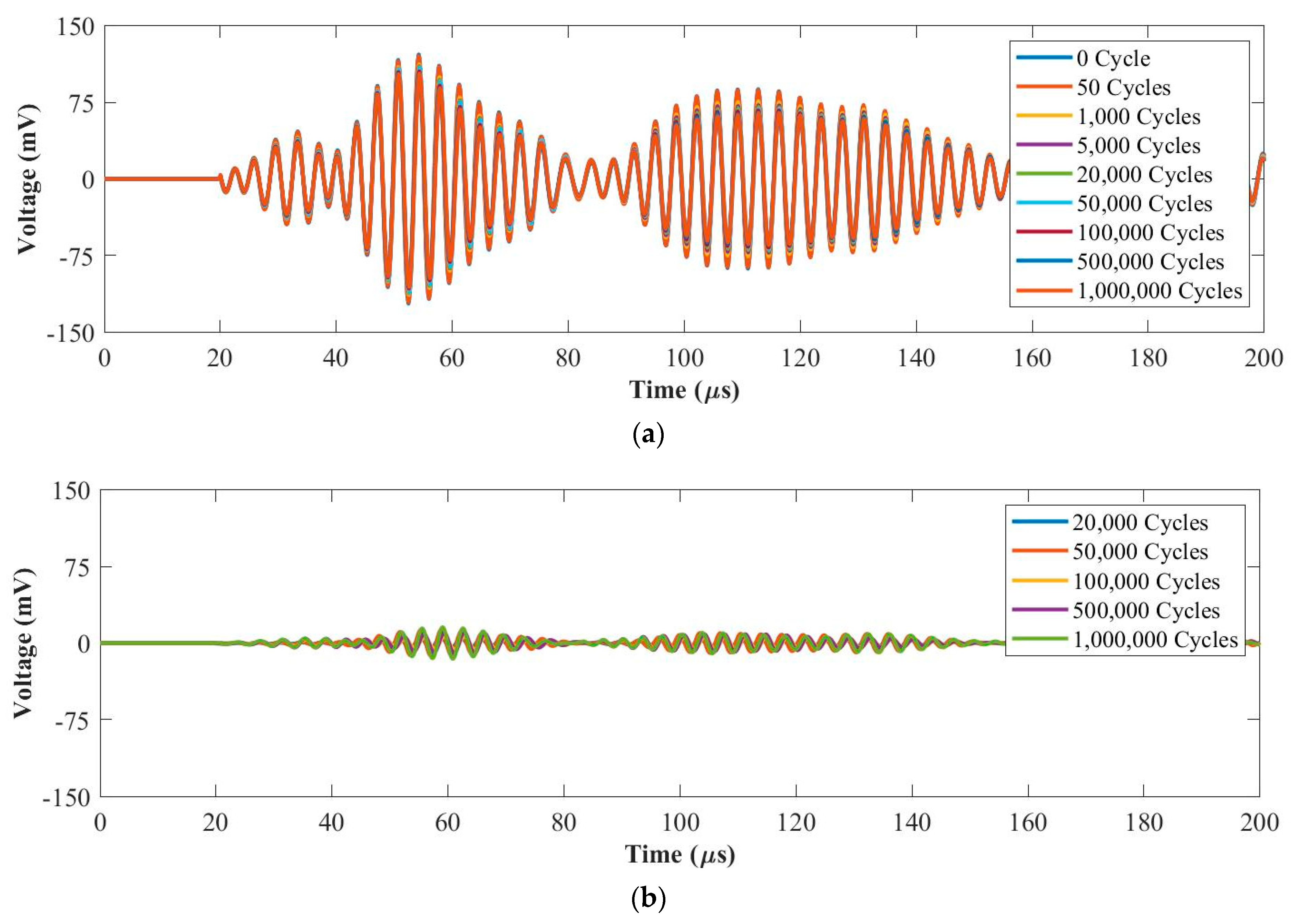
3.2.2. Fatigue Force Range 2: 1~10 kN
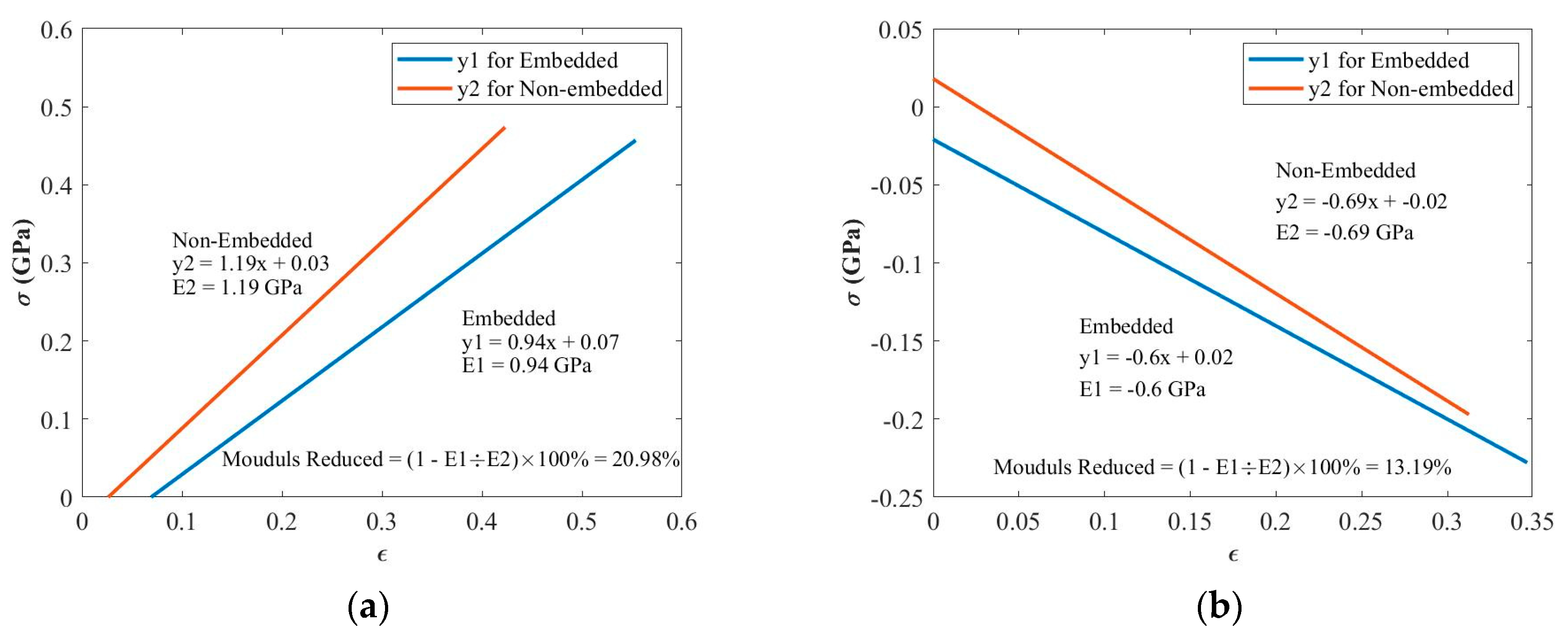
4. Tensile and Compressive Tests
5. Conclusions
Author Contributions
Funding
Institutional Review Board Statement
Informed Consent Statement
Data Availability Statement
Acknowledgments
Conflicts of Interest
References
- Nag-Chowdhury, S.; Bellegou, H.; Pillin, I.; Castro, M.; Longrais, P.; Feller, J. Non-intrusive health monitoring of infused composites with embedded carbon quantum piezo-resistive sensors. Compos. Sci. Technol. 2016, 123, 286–294. [Google Scholar] [CrossRef]
- Atescan, Y.; Cebeci, H. In-situ Structural Health Monitoring of Carbon Fiber Reinforced Composites with CNT Smart Paint. In Proceedings of the 24th AIAA/AHS Adaptive Structures Conference, San Diego, CA, USA, 4–8 January 2016; p. 1792. [Google Scholar]
- Roundi, W.; El Mahi, A.; El Gharad, A.; Rebiere, J.-L. Acoustic emission monitoring of damage progression in glass/epoxy composites during static and fatigue tensile tests. Appl. Acoust. 2018, 132, 124–134. [Google Scholar] [CrossRef]
- Belhouideg, S.; Lagache, M. Effect of embedded strain gage on the mechanical behavior of composite structures. J. Mod. Mater. 2018, 5, 1–7. [Google Scholar] [CrossRef] [Green Version]
- Barile, C.; Casavola, C.; De Cillis, F. Mechanical comparison of new composite materials for aerospace applications. Compos. Part B Eng. 2019, 162, 122–128. [Google Scholar] [CrossRef]
- Giurgiutiu, V. Structural Health Monitoring with Piezoelectric Wafer Active Sensors; Academic Press: Oxford, UK, 2014. [Google Scholar]
- Yuan, F.-G. Structural Health Monitoring (SHM) in Aerospace Structures; Woodhead Publishing: Duxford, UK, 2016. [Google Scholar]
- Dafydd, I.; Sharif Khodaei, Z. Analysis of barely visible impact damage severity with ultrasonic guided Lamb waves. Struct. Health Monit. 2020, 19, 1104–1122. [Google Scholar] [CrossRef]
- Yue, N.; Aliabadi, M. A scalable data-driven approach to temperature baseline reconstruction for guided wave structural health monitoring of anisotropic carbon-fibre-reinforced polymer structures. Struct. Health Monit. 2020, 19, 1487–1506. [Google Scholar] [CrossRef]
- Ruzek, R.; Kadlec, M.; Tserpes, K.; Karachalios, E. Monitoring of compressive behaviour of stiffened composite panels using embedded fibre optic and strain gauge sensors. Int. J. Struct. Integr. 2017, 8. [Google Scholar] [CrossRef]
- Nisha, M.; Singh, D.; Rajaraman, A. Development of Continuous and Real Time Structural Health Monitoring of Aircraft Primary Structure Through Embedded Carbon Nano Fiber Sensors. Int. J. Veh. Struct. Syst. 2016, 8, 74. [Google Scholar] [CrossRef]
- Lin, M.; Chang, F.-K. The manufacture of composite structures with a built-in network of piezoceramics. Compos. Sci. Technol. 2002, 62, 919–939. [Google Scholar] [CrossRef]
- Feng, T.; Bekas, D.; Aliabadi, M. Active Health Monitoring of Thick Composite Structures by Embedded and Surface-Mounted Piezo Diagnostic Layer. Sensors 2020, 20, 3410. [Google Scholar] [CrossRef]
- Masmoudi, S.; El Mahi, A.; Turki, S. Fatigue behaviour and structural health monitoring by acoustic emission of E-glass/epoxy laminates with piezoelectric implant. Appl. Acoust. 2016, 108, 50–58. [Google Scholar] [CrossRef]
- Karpenko, O.; Khomenko, A.; Koricho, E.; Haq, M.; Udpa, L. Monitoring of fatigue damage in composite lap-joints using guided waves and FBG sensors. In Proceedings of the AIP Conference Proceedings, Minneapolis, MN, USA, 26–31 July 2015; p. 120005. [Google Scholar]
- Kocaman, E.S.; Akay, E.; Yilmaz, C.; Turkmen, H.S.; Misirlioglu, I.B.; Suleman, A.; Yildiz, M. Monitoring the damage state of fiber reinforced composites using an FBG network for failure prediction. Materials 2017, 10, 32. [Google Scholar] [CrossRef] [PubMed] [Green Version]
- Li, F.; Du, Y.; Sun, X.; Zhao, W. Sensing performance assessment of twisted CFRP with embedded fiber Bragg grating sensors subjected to monotonic and fatigue loading. Sens. Actuators A Phys. 2018, 271, 153–161. [Google Scholar] [CrossRef]
- Karatas, C.; Degerliyurt, B.; Yaman, Y.; Sahin, M. Fibre Bragg grating sensor applications for structural health monitoring. Aircr. Eng. Aerosp. Technol. 2018, 92. [Google Scholar] [CrossRef]
- Souza, G.; Tarpani, J. Distributed Fiber Optics Sensing Applied to Laminated Composites: Embedding Process, Strain Field Monitoring with OBR and Fracture Mechanisms. J. Nondestruct. Eval. 2020, 39, 1–15. [Google Scholar] [CrossRef]
- Aly, K.; Li, A.; Bradford, P.D. Compressive piezoresistive behavior of carbon nanotube sheets embedded in woven glass fiber reinforced composites. Compos. Part B Eng. 2017, 116, 459–470. [Google Scholar] [CrossRef]
- Ahmed, S.; Thostenson, E.T.; Schumacher, T.; Doshi, S.M.; McConnell, J.R. Integration of carbon nanotube sensing skins and carbon fiber composites for monitoring and structural repair of fatigue cracked metal structures. Compos. Struct. 2018, 203, 182–192. [Google Scholar] [CrossRef]
- Bekas, D.G.; Sharif-Khodaei, Z.; Baltzis, D.; Aliabadi, M.H.F.; Paipetis, A.S. Quality assessment and damage detection in nanomodified adhesively-bonded composite joints using inkjet-printed interdigital sensors. Compos. Struct. 2019, 211, 557–563. [Google Scholar] [CrossRef]
- Masmoudi, S.; El Mahi, A.; Turki, S. Use of piezoelectric as acoustic emission sensor for in situ monitoring of composite structures. Compos. Part B Eng. 2015, 80, 307–320. [Google Scholar] [CrossRef]
- Tuloup, C.; Harizi, W.; Aboura, Z.; Meyer, Y. Integration of piezoelectric transducers (PZT and PVDF) within polymer-matrix composites for structural health monitoring applications: New success and challenges. Int. J. Smart Nano Mater. 2020, 11, 343–369. [Google Scholar] [CrossRef]
- Andreades, C.; Mahmoodi, P.; Ciampa, F. Characterisation of smart CFRP composites with embedded PZT transducers for nonlinear ultrasonic applications. Compos. Struct. 2018, 206, 456–466. [Google Scholar] [CrossRef]
- Andreades, C.; Meo, M.; Ciampa, F. Fatigue testing and damage evaluation using smart CFRP composites with embedded PZT transducers. Mater. Today Proc. 2021, 34, 260–265. [Google Scholar] [CrossRef]
- Sharif-Khodaei, Z.; Ghajari, M.; Aliabadi, M. Impact damage detection in composite plates using a self-diagnostic electro-mechanical impedance-based structural health monitoring system. J. Multiscale Model. 2015, 6, 1550013. [Google Scholar] [CrossRef] [Green Version]
- Park, G.; Farrar, C.R.; Rutherford, A.C.; Robertson, A.N. Piezoelectric active sensor self-diagnostics using electrical admittance measurements. J. Vib. Acoust. 2006, 128, 469–476. [Google Scholar] [CrossRef]
- Park, G.; Farrar, C.R.; di Scalea, F.L.; Coccia, S. Performance assessment and validation of piezoelectric active-sensors in structural health monitoring. Smart Mater. Struct. 2006, 15, 1673. [Google Scholar] [CrossRef]
- Wang, D.; Song, H.; Zhu, H. Embedded 3D electromechanical impedance model for strength monitoring of concrete using a PZT transducer. Smart Mater. Struct. 2014, 23, 115019. [Google Scholar] [CrossRef]
- Lim, Y.Y.; Liew, W.Y.H.; Soh, C.K. A parametric study on admittance signatures of a PZT transducer under free vibration. Mech. Adv. Mater. Struct. 2015, 22, 877–884. [Google Scholar] [CrossRef]
- Zou, F.; Benedetti, I.; Aliabadi, M.H. A boundary element model for structural health monitoring using piezoelectric transducers. Smart Mater. Struct. 2013, 23, 015022. [Google Scholar] [CrossRef] [Green Version]


| No. | Embedding Technique | Effects of Embedding on Different Mechanical Tests |
|---|---|---|
| 1 | SMART Layers | Did not degrade for mechanical properties when embedded in a relatively small section of the part. |
| 2 | PZT with wires | Mechanical resistance and longitudinal strain 6% and 11% ↑; Elastic modulus and Poisson’s ratio 5% and 26% ↓. |
| 3 | PZT with wires | Using E-glass to cover embedded sensors: no effects on the integrity for mechanical properties. |
| 4 | Diagnosed film with PZT | Fatigue test: EMI and sensing performance remained good. Tensile and compressive modules: 20.98% and 13.19% ↓ when the diagnosed film embedded across the entire layer. |
| No. | Loading Cycles |
|---|---|
| 1 | 0 |
| 2 | 50 |
| 3 | 1000 |
| 4 | 5000 |
| 5 | 20,000 |
| 6 | 50,000 |
| 7 | 100,000 |
| 8 | 500,000 |
| 9 | 1,000,000 |
Publisher’s Note: MDPI stays neutral with regard to jurisdictional claims in published maps and institutional affiliations. |
© 2021 by the authors. Licensee MDPI, Basel, Switzerland. This article is an open access article distributed under the terms and conditions of the Creative Commons Attribution (CC BY) license (https://creativecommons.org/licenses/by/4.0/).
Share and Cite
Feng, T.; Aliabadi, M.H.F. Structural Integrity Assessment of Composites Plates with Embedded PZT Transducers for Structural Health Monitoring. Materials 2021, 14, 6148. https://doi.org/10.3390/ma14206148
Feng T, Aliabadi MHF. Structural Integrity Assessment of Composites Plates with Embedded PZT Transducers for Structural Health Monitoring. Materials. 2021; 14(20):6148. https://doi.org/10.3390/ma14206148
Chicago/Turabian StyleFeng, Tianyi, and M.H. Ferri Aliabadi. 2021. "Structural Integrity Assessment of Composites Plates with Embedded PZT Transducers for Structural Health Monitoring" Materials 14, no. 20: 6148. https://doi.org/10.3390/ma14206148
APA StyleFeng, T., & Aliabadi, M. H. F. (2021). Structural Integrity Assessment of Composites Plates with Embedded PZT Transducers for Structural Health Monitoring. Materials, 14(20), 6148. https://doi.org/10.3390/ma14206148