
Load-Bearing Capacity of Beams Reinforced with Composite Rebar in Regard to Existing Guidelines


Abstract
:1. Introduction
2. Materials and Methods
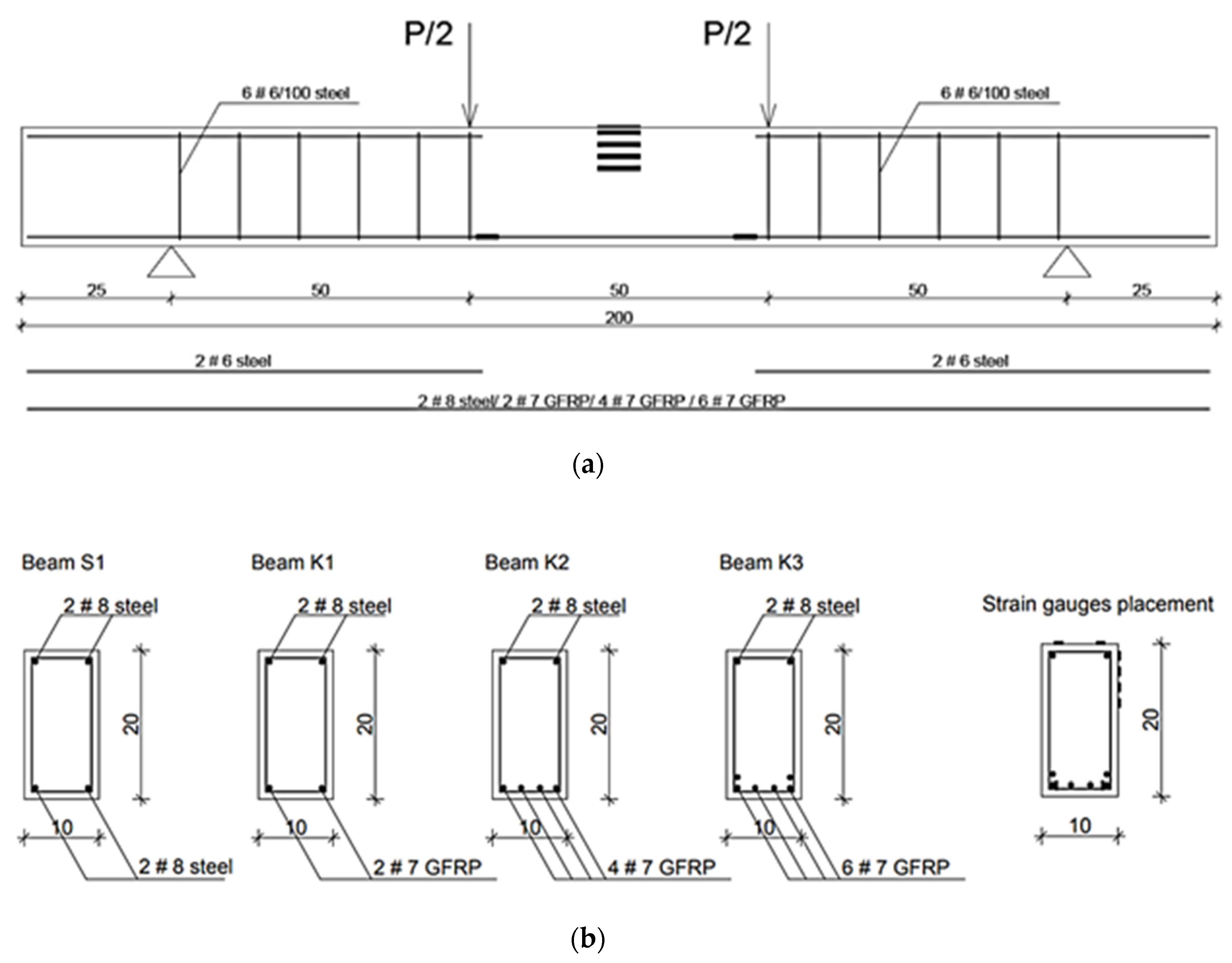
2.1. Specimen
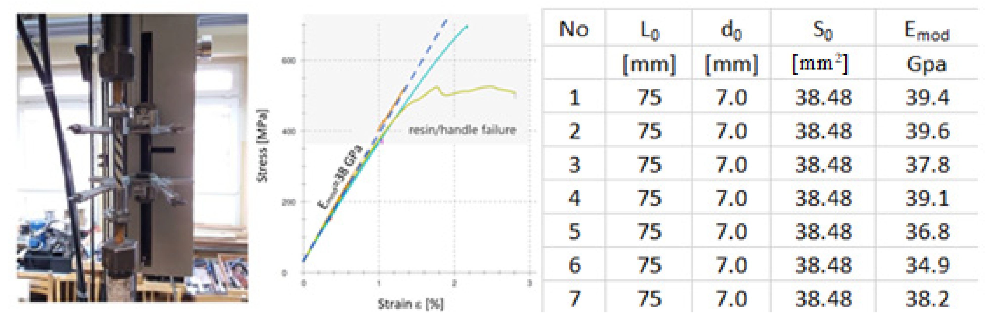
2.2. Material Properties
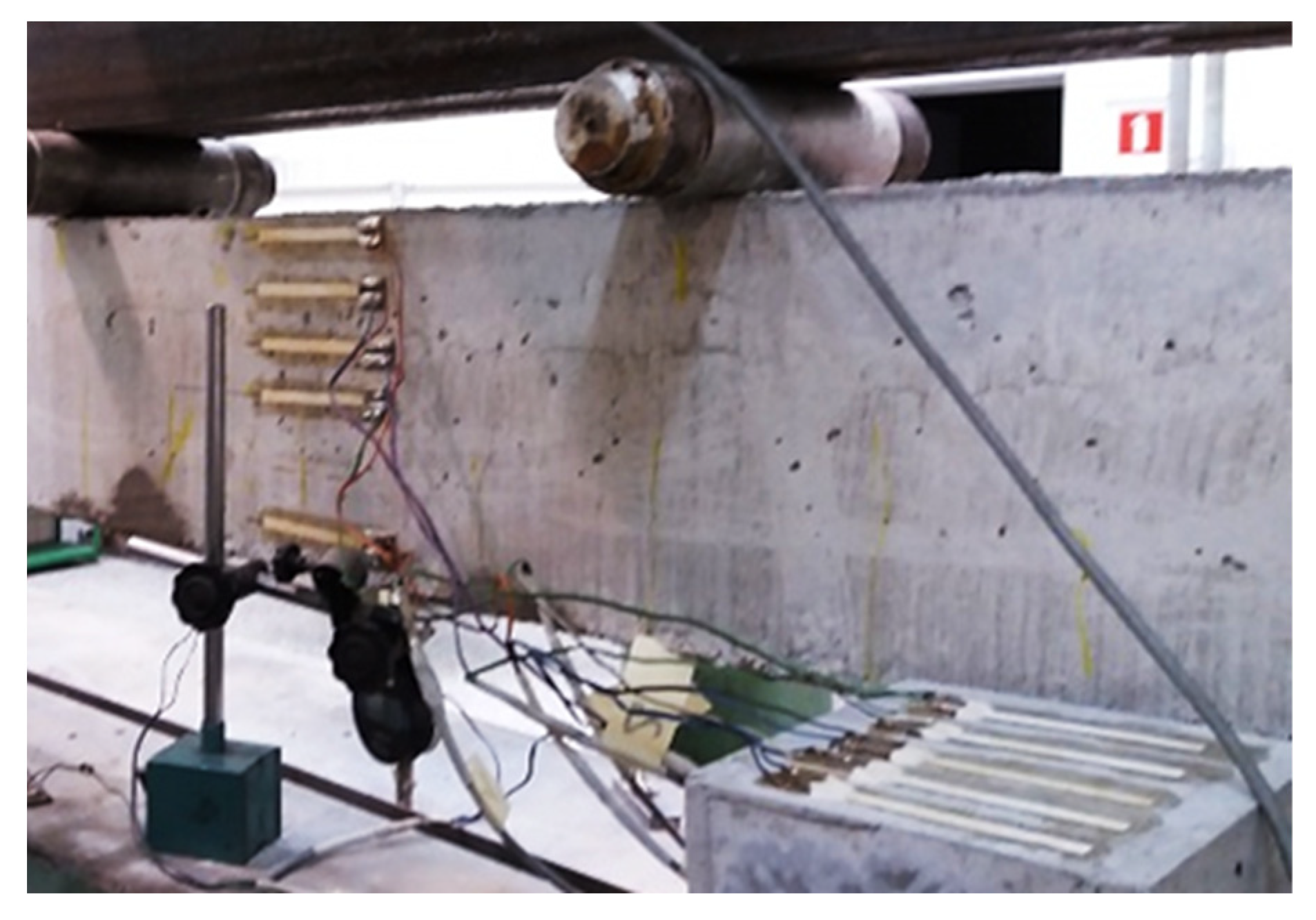
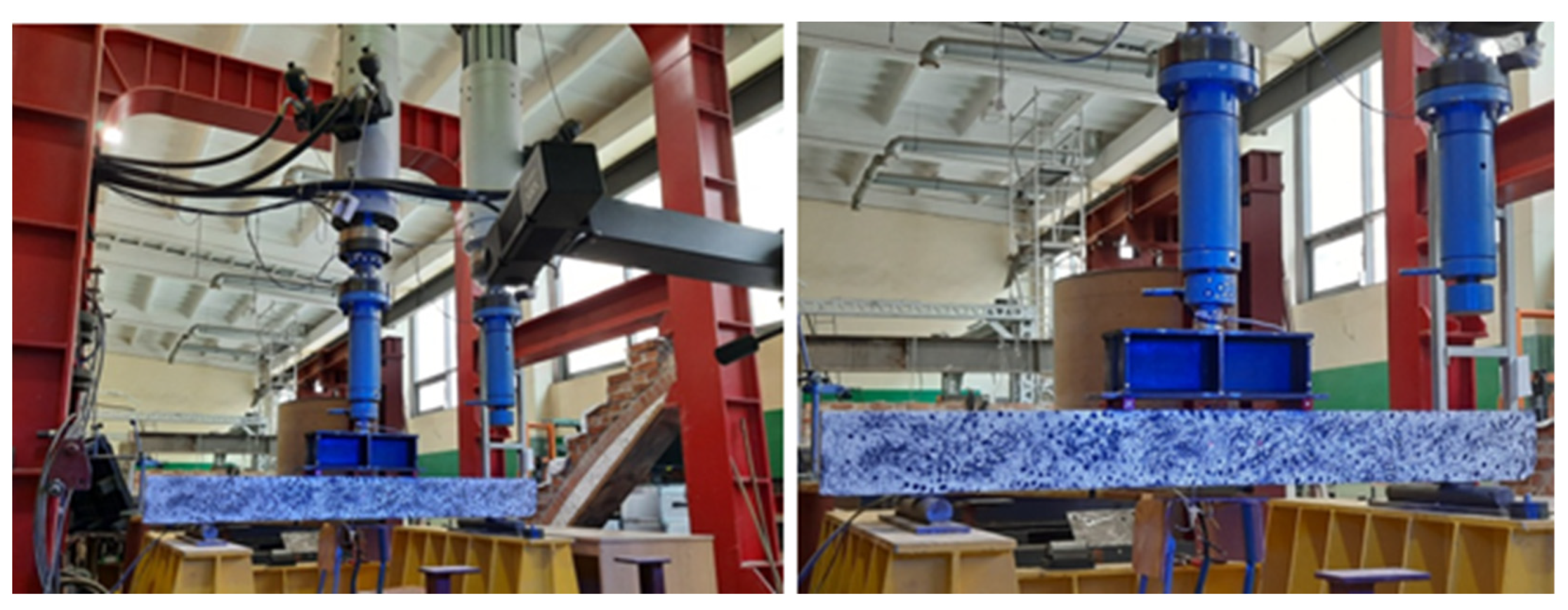
2.3. Test Setup
3. Results
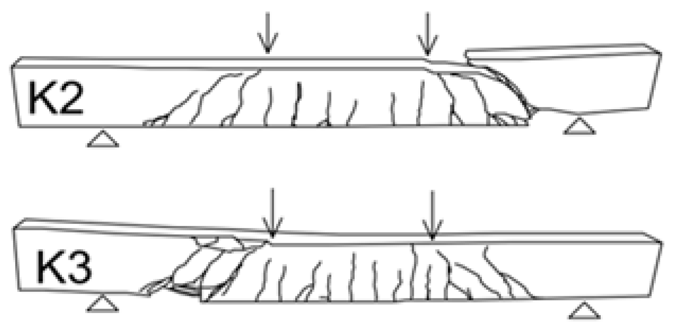
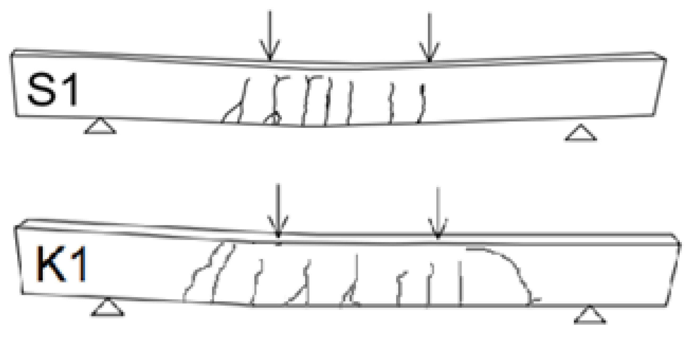
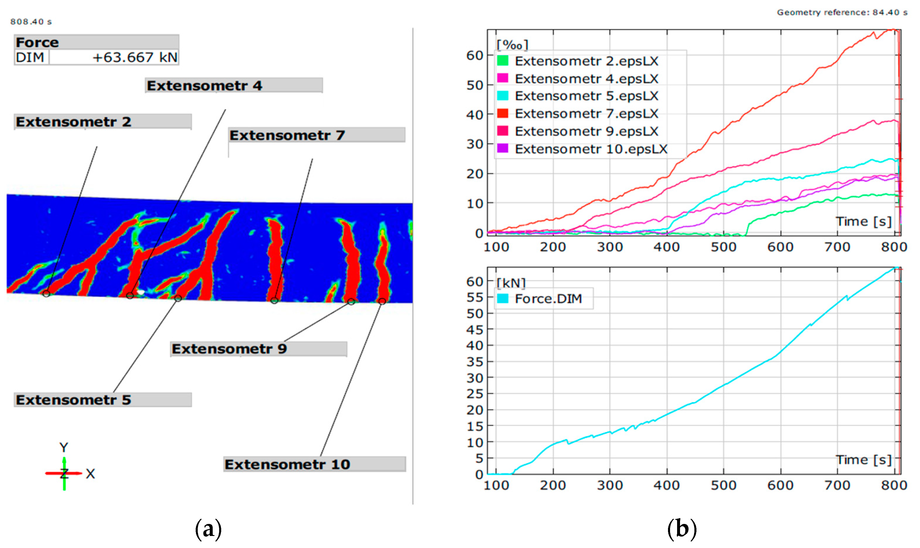
3.1. Crack Pattern and Deflection
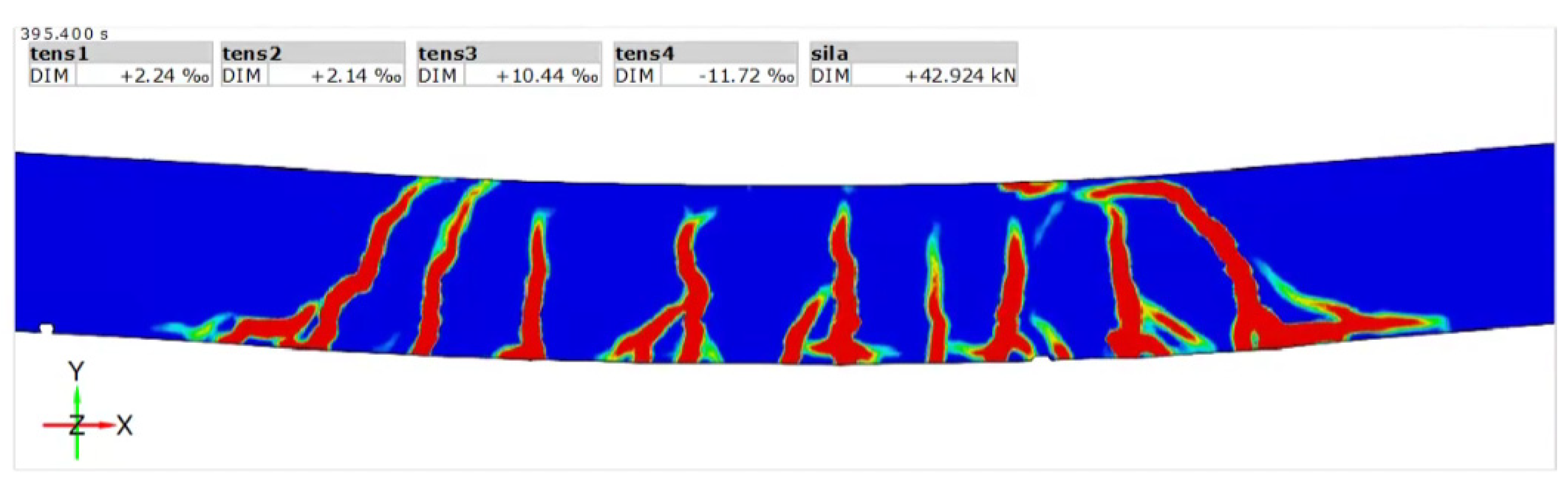
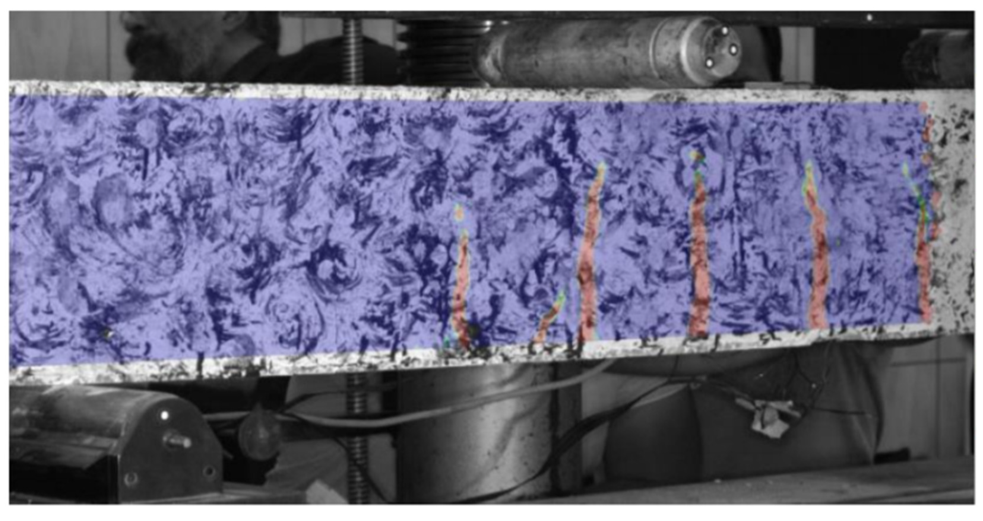
3.2. Optical Measurements
3.3. Failure Mechanism and Deformations
3.4. Comparison between the Standards
4. Discussion
5. Conclusions
- GFRP reinforced beams during bending tests exhibited cracks of greater depth than those found in steel-reinforced beams. Immediately before failure, the cracks reach up to 90% of the section height and have a much larger width.
- The use of composite bars, due to their lower modulus of elasticity than steel, increases the deflection of bending elements under the same load, after the section exhibits cracking. The influence of extended deformations on the load-bearing capacity of reinforced elements should be further studied.
- The serviceability limit state (SLS) plays a much greater role in the case of elements reinforced with composite bars than with steel reinforcement. However, it is necessary to update the limits for elements reinforced with composite rebar. Due to the chemical resistance and lack of corrosion of GFRP bars, the elements will be durable even after extensive cracking. The authors think that the allowed crack width should be increased beyond 0.4 mm.
- GFRP bars, due to their low Young’s modulus, can be successfully used in elements where the deformability is not important for the structural integrity, e.g., weakly reinforced concrete elements, floors, and thermal insulation connectors.
- The GFRP reinforcement partial factors for strength reduction recommended by standards and instructions in the calculations of the ultimate limit state reduce the load-bearing capacity of the element so much that the cross-section of the composite reinforcement resembles the cross-section of steel reinforced element. This does not protect against excessive cracks and high deflection. In view of the above, the gain from using GFRP in typical elements should be seen in higher chemical resistance, lower thermal conductivity, and where the reinforcement is only an addition.
- The anisotropy of the GFRP bars causes susceptibility to local damages, which can result in a lower bearing capacity in bended elements with high deflection and extensive cracks. This might be of great importance in elements with low degree of reinforcement.
Author Contributions
Funding
Institutional Review Board Statement
Informed Consent Statement
Data Availability Statement
Conflicts of Interest
References
- Emparanza, A.R.; Kampmann, R.; De Caso y Basalo, F. (Eds.) State-of-the-Practice of Global Manufacturing of FRP Rebar and Specifications; ACI Fall Convention 2017; American Concrete Institute: Orlando, FL, USA, 2017. [Google Scholar]
- Fiore, V.; Di Bella, G.; Valenza, A. Glass–basalt/epoxy hybrid composites for marine applications. Mater. Des. 2011, 32, 2091–2099. [Google Scholar] [CrossRef]
- Inman, M.; Thorhallsson, E.R.; Azrague, K. A Mechanical and Environmental Assessment and Comparison of Basalt Fibre Reinforced Polymer (BFRP) Rebar and Steel Rebar in Concrete Beams. Energy Procedia 2017, 111, 31–40. [Google Scholar] [CrossRef]
- Wei, B.; Cao, H.; Song, S. Tensile behavior contrast of basalt and glass fibers after chemical treatment. Mater. Des. 2010, 31, 4244–4250. [Google Scholar] [CrossRef]
- Szumigała, M.; Pawłowski, D. Zastosowanie kompozytowych prętów zbrojeniowych w konstrukcjach budowlanych. Przegląd Bud. 2014, 3, 47–50. [Google Scholar]
- Rduch, A.; Rduch, Ł.; Walentyński, R. Właściwości i zastosowanie kompozytowych prętów zbrojeniowych. Przegląd Bud. 2017, 11, 43–46. [Google Scholar]
- Fédération Internationale du Béton. FRP Reinforcement in RC Structures, 2007, Bulletin 40. Available online: http://compositegroupworld.com/pdf/40%20-%20FRP%20reinforcement%20in%20RC%20structures.pdf (accessed on 14 October 2021).
- Hollaway, L.C. A review of the present and future utilisation of FRP composites in the civil infrastructure with reference to their important in-service properties. Constr. Build. Mater. 2010, 24, 2419–2445. [Google Scholar] [CrossRef]
- Gay, D. Composite Materials: Design and Applications/Daniel Gay, 3rd ed.; CRC Press: Boca Raton, FL, USA, 2014; ISBN 9781466584877. [Google Scholar]
- Gibson, R.F. Principles of Composite Material Mechanics; CRC Press: Boca Raton, FL, USA, 2016; ISBN 9780429190582. [Google Scholar]
- Thériault, M.; Benmokrane, B. Effects of FRP Reinforcement Ratio and Concrete Strength on Flexural Behavior of Concrete Beams. J. Compos. Constr. 1998, 2, 7–16. [Google Scholar] [CrossRef]
- Bentz, E.C.; Massam, L.; Collins, M.P. Shear Strength of Large Concrete Members with FRP Reinforcement. J. Compos. Constr. 2010, 14, 637–646. [Google Scholar] [CrossRef]
- Alam, M.S.; Hussein, A. Experimental investigation on the effect of longitudinal reinforcement on shear strength of fibre reinforced polymer reinforced concrete beams. Can. J. Civ. Eng. 2011, 38, 243–251. [Google Scholar] [CrossRef]
- Ashour, A.F. Flexural and shear capacities of concrete beams reinforced with GFRP bars. Constr. Build. Mater. 2006, 20, 1005–1015. [Google Scholar] [CrossRef]
- Pawłowski, D. The Influence of Short-Term Static Load on Behaviour of Basalt-Fiber Reinforced Polymer Reinforced Concrete Beams. Ph.D. Thesis, Politechnika Poznańska, Poznań, Poland, 2016. [Google Scholar]
- Firmo, J.P.; Arruda, M.R.T.; Correia, J.R.; Tiago, C. Flexural behaviour of partially bonded carbon fibre reinforced polymers strengthened concrete beams: Application to fire protection systems design. Mater. Des. 2015, 65, 1064–1074. [Google Scholar] [CrossRef]
- Santarsiero, G. FE Modelling of the Seismic Behavior of Wide Beam-Column Joints Strengthened with CFRP Systems. Buildings 2018, 8, 31. [Google Scholar] [CrossRef] [Green Version]
- Pilakoutas, K.; Guadagnini, M.; Neocleous, K.; Matthys, S. Design guidelines for FRP reinforced concrete structures. Proc. Inst. Civ. Eng.-Struct. Build. 2011, 164, 255–263. [Google Scholar] [CrossRef] [Green Version]
- Hollaway, L.; Teng, J.G. Strengthening and Rehabilitation of Civil Infrastructures Using Fibre-Reinforced Polymer (FRP) Composites; Woodhead Publishing: Boca Raton, FL, USA; Cambridge, UK; Sawstone, UK, 2008; ISBN 978-1-84569-448-7. [Google Scholar]
- JSCE. Recommendation for Design and Construction of Concrete Structures Using Continuous Fibre Reinforcing Materials; Japan Society of Civil Engineers: Tokyo, Japan, 1997. [Google Scholar]
- Canadian Standards Association. Design and Construction of Building Components with Fibre-Reinforced Polymers; (S806-02); CSA: Mississauga, ON, Canada, 2007.
- Rizkalla, S.H.; Mufti, A.A. Reinforcing Concrete Structures with Fibre Reinforced Polymers; ISIS Canada: Winnipeg, MB, Canada, 2001; ISBN 0-9689006-6-6. [Google Scholar]
- American Concrete Institute. Guide for the Design and Construction of Structural Concrete Reinforced with FRP Bars; ACI Commitee 440 (ACI 440.1R-15); American Concrete Institute: Indianapolis, IN, USA, 2015. [Google Scholar]
- National Research Council. Guide for the Design and Construction of Concrete Structures Reinforced with Fiber-Reinforced Polymer Bars; (CNR-DT-203/2006); CNR Advisory Committee on Technical Recommendations for Construction: Rome, Italy, 2007.
- CEN/TS. Task Group 1 Strengthening and Reinforcing with Fibre Reinforced Polymers; (250/SC 2/WG 1/TG 1); European Committee for Standarization: Brussels, Belgium, 2019. [Google Scholar]
- Renata, K. (Ed.) Wymiarowanie i Kształtowanie Wybranych Konstrukcji Betonowych ze Zbrojeniem Niemetalicznym; XXXIII Ogólnopolskie Warsztaty Pracy Projektanta Konstrukcji: Szczyrk, Poland, 2018. [Google Scholar]
- Nanni, A. Fiber-Reinforced-Plastic (FRP) Reinforcement for Concrete Structures: Properties and Applications; Elsevier: Amsterdam, The Netherlands; New York, NY, USA, 1993; ISBN 9781483291437. [Google Scholar]
- Nanni, A. Guides and Specifications for the Use of Composites in Concrete and Masonry Construction in North America. In Composites in Construction, Proceedings of the International Workshop on Composites in Construction, Capri, Italy, 20–21 July 2001; Cosenza, E., Manfredi, G., Nanni, A., Eds.; American Society of Civil Engineers: Reston, VA, USA, 2001; pp. 9–18. ISBN 978-0-7844-0596-3. [Google Scholar]
- European Committee for Standarization. EN 1992-1-1 Eurocode 2: Design of Concrete Structures—Part 1-1: General Rules and Rules for Buildings; European Committee for Standarization: Brussels, Belgium, 1992. [Google Scholar]
- Tomlinson, D.; Fam, A. Performance of Concrete Beams Reinforced with Basalt FRP for Flexure and Shear. J. Compos. Constr. 2015, 19, 4014036. [Google Scholar] [CrossRef]
- Brik, V.B. Advanced Concept Concrete Using Basalt Fiber/BF Composite Rebar Reinforcement: Report for Highway-IDEA Project 86; Transportation Research Board: Madison, WI, USA, 2003.
- Ovitigala, B.T.; Ibrahim, M.A.; Issa, M.A. Serviceability and Ultimate Load Behavior of Concrete Beams Reinforced with Basalt Fiber-Reinforced Polymer Bars. ACI Struct. J. 2016, 113. [Google Scholar] [CrossRef]
- Bažant, Z.P.; Planas, J. Fracture and Size Effect in Concrete and Other Quasibrittle Materials; CRC Press: Boca Raton, FL, USA; London, UK, 1998; ISBN 9780849382840. [Google Scholar]
- Bažant, Z.P. Size Effect in Blunt Fracture: Concrete, Rock, Metal. J. Eng. Mech. 1984, 110, 518–535. [Google Scholar] [CrossRef]
- Karihaloo, B.L.; Abdalla, H.M.; Xiao, Q.Z. Size effect in concrete beams. Eng. Fract. Mech. 2003, 70, 979–993. [Google Scholar] [CrossRef]
- Syroka-Korol, E.; Tejchman, J. Experimental investigations of size effect in reinforced concrete beams failing by shear. Eng. Struct. 2014, 58, 63–78. [Google Scholar] [CrossRef]
- Baena, M.; Torres, L.; Turon, A.; Barris, C. Experimental study of bond behaviour between concrete and FRP bars using a pull-out test. Compos. Part B Eng. 2009, 40, 784–797. [Google Scholar] [CrossRef]
- Di, B.; Wang, J.; Li, H.; Zheng, J.; Zheng, Y.; Song, G. Investigation of Bonding Behavior of FRP and Steel Bars in Self-Compacting Concrete Structures Using Acoustic Emission Method. Sensors 2019, 19, 159. [Google Scholar] [CrossRef] [Green Version]
- Jumaa, G.B.; Yousif, A.R. Size effect on the shear failure of high-strength concrete beams reinforced with basalt FRP bars and stirrups. Constr. Build. Mater. 2019, 209, 77–94. [Google Scholar] [CrossRef]
- Huang, Z.; Chen, W.; Tran, T.T.; Pham, T.M.; Hao, H.; Chen, Z.; Elchalakani, M. Experimental and numerical study on concrete beams reinforced with Basalt FRP bars under static and impact loads. Compos. Struct. 2021, 263, 113648. [Google Scholar] [CrossRef]
- Protchenko, K.; Leśniak, P.; Szmigiera, E.; Urbański, M. New Model for Analytical Predictions on the Bending Capacity of Concrete Elements Reinforced with FRP Bars. Materials 2021, 14, 693. [Google Scholar] [CrossRef]


| Component | Amount |
|---|---|
| Fine aggregate 0–2 mm | 624 kg/m3 |
| Coarse aggregate 2–8 mm | 1072 kg/m3 |
| Cement CEM I 42.5 R | 450 kg/m3 |
| Fly ash | 72 kg/m3 |
| Silica fume | 38 kg/m3 |
| Water | 155 kg/m3 |
| Superplasticizer SIKA Viscocrete-3 | 11 kg/m3 |
| Property | Type of Reinforcement | |
|---|---|---|
| Steel | GFRP | |
| Density (g/cm3) | 7.85 | 1.25–2.1 |
| Yield stress (MPa) | 500 | – |
| Tensile strength (MPa) | 550 | >1000 |
| Modulus of elasticity (GPa) | 210 | 35–51 |
| Plastic deformation (%) | 0.14–0.125 | – |
| Deformation at failure (%) | 6.0–12.0 | 1.2–3.1 |
| Beam S1 | Beam K1 | Beam K2 | Beam K3 | |
|---|---|---|---|---|
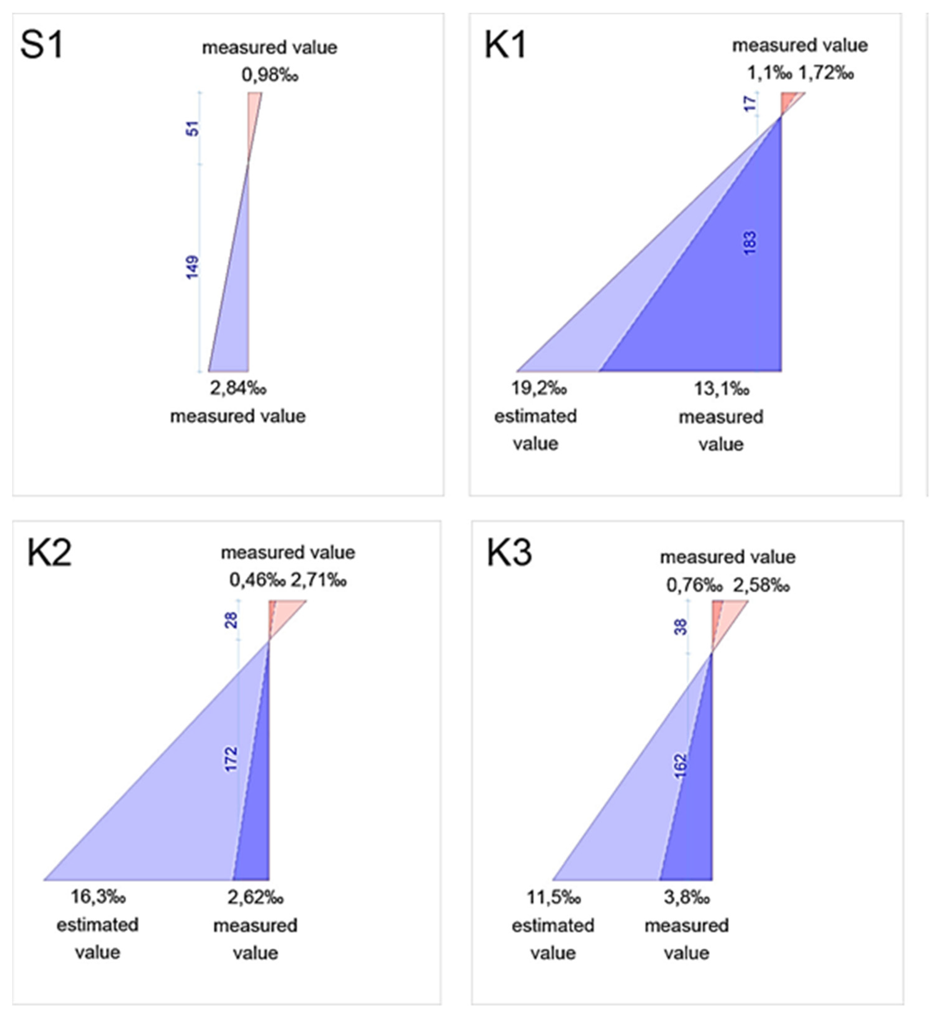
| Max. width (mm) | 0.4 mm | 0.8 mm | 0.9 mm | 0.8 mm |
| Deflection | 9.1 mm | 22.1 mm | 15.2 mm | 12.3 mm |
| Beam S1 2#8 | Mexp (kNm) | 10.15 | ||
|---|---|---|---|---|
| Instruction | EN 1992-1-1 | CNR-DT 203/2006 | ACI 440.1R-15 | JSCE 1997 |
| Characteristic Mrk (kNm) | 8.82 | - | - | - |
| Design Mrd (kNm) | 7.61 | - | - | - |
| Failure mechanism | bars | |||
| Partial factors | γs = 1.15; γc = 1.50 | |||
| Beam K1 2#7 | Mexp (kNm) | 10.73 | ||
| Instruction | EN 1992-1-1 | CNR-DT 203/2006 | ACI 440.1R-15 | JSCE 1997 |
| Characteristic Mrk (kNm) | 13.35 | 13.35 | 12.43 | 13.35 |
| Design Mrd (kNm) | 10.21 | 5.78 | 5.82 | 10.46 |
| Failure mechanism | bars | bars | bars | bars |
| Partial factors | γf = 1.30; γc = 1.50 | γm = 1.50; ηa = 0.8; ηl = 0.8; | β1 = 0.654; CE.G = 0.8; Φ = 0.55 | γmf = 1.15; γc = 1.50 |
| Beam K2 4#7 | Mexp (kNm) | 16.25 | ||
| Instruction | EN 1992-1-1 | CNR-DT 203/2006 | ACI 440.1R-15 | JSCE 1997 |
| Characteristic Mrk (kNm) | 16.74 | 16.74 | 16.79 | 21.82 |
| Design Mrd (kNm) | 11.16 | 11.16 | 10.92 | 13.86 |
| Failure mechanism | concrete | concrete | concrete | concrete |
| Partial factors | γf = 1.30; γc = 1.50 | γm = 1.50; ηa = 0.8; ηl = 0.8; | β1 = 0.654; CE.G = 0.8; Φ = 0.65 | γmf = 1.15; γc = 1.50 |
| Beam K3 6#7 | Mexp (kNm) | 19.15 | ||
| Instruction | EN 1992-1-1 | CNR-DT 203/2006 | ACI 440.1R-15 | JSCE 1997 |
| Characteristic Mrk (kNm) | 16.74 | 16.74 | 19.87 | 25.82 |
| Design Mrd (kNm) | 11.16 | 11.16 | 12.92 | 16.17 |
| Failure mechanism | concrete | concrete | concrete | concrete |
| Partial factors | γf = 1.30; γc = 1.50 | γm = 1.50; ηa = 0.8; ηl = 0.8; | β1 = 0.654; CE.G = 0.8; Φ = 0.65 | γmf = 1.15; γc = 1.50 |
| Beam S1 2#8 | ||||
|---|---|---|---|---|
| Mexp/Mrk | 1.15 | |||
| Mexp/Mrd | 1.33 | |||
| Beam K1 2#7 | ||||
| Instruction | EN 1992-1-1 | CNR-DT 203/2006 | ACI 440.1R-15 | JSCE 1997 |
| Mexp/Mrk | 0.80 | 0.80 | 0.86 | 0.80 |
| Mexp/Mrd | 1.05 | 1.86 | 1.84 | 1.03 |
| Beam K2 4#7 | ||||
| Instruction | EN 1992-1-1 | CNR-DT 203/2006 | ACI 440.1R-15 | JSCE 1997 |
| Mexp/Mrk | 0.97 | 0.97 | 0.97 | 0.74 |
| Mexp/Mrd | 1.46 | 1.46 | 1.49 | 1.17 |
| Beam K3 6#7 | ||||
| Instruction | EN 1992-1-1 | CNR-DT 203/2006 | ACI 440.1R-15 | JSCE 1997 |
| Mexp/Mrk | 1.14 | 1.14 | 0.96 | 0.74 |
| Mexp/Mrd | 1.72 | 1.72 | 1.48 | 1.18 |
Publisher’s Note: MDPI stays neutral with regard to jurisdictional claims in published maps and institutional affiliations. |
© 2021 by the authors. Licensee MDPI, Basel, Switzerland. This article is an open access article distributed under the terms and conditions of the Creative Commons Attribution (CC BY) license (https://creativecommons.org/licenses/by/4.0/).
Share and Cite
Olczyk, N.; Błyszko, J.; Techman, M. Load-Bearing Capacity of Beams Reinforced with Composite Rebar in Regard to Existing Guidelines. Materials 2021, 14, 6116. https://doi.org/10.3390/ma14206116
Olczyk N, Błyszko J, Techman M. Load-Bearing Capacity of Beams Reinforced with Composite Rebar in Regard to Existing Guidelines. Materials. 2021; 14(20):6116. https://doi.org/10.3390/ma14206116
Chicago/Turabian StyleOlczyk, Norbert, Jarosław Błyszko, and Mateusz Techman. 2021. "Load-Bearing Capacity of Beams Reinforced with Composite Rebar in Regard to Existing Guidelines" Materials 14, no. 20: 6116. https://doi.org/10.3390/ma14206116
APA StyleOlczyk, N., Błyszko, J., & Techman, M. (2021). Load-Bearing Capacity of Beams Reinforced with Composite Rebar in Regard to Existing Guidelines. Materials, 14(20), 6116. https://doi.org/10.3390/ma14206116