
Effect of Defocused Nanosecond Laser Paint Removal on Mild Steel Substrate in Ambient Atmosphere


Abstract
:1. Introduction
2. Materials and Methods
2.1. Raw Materials
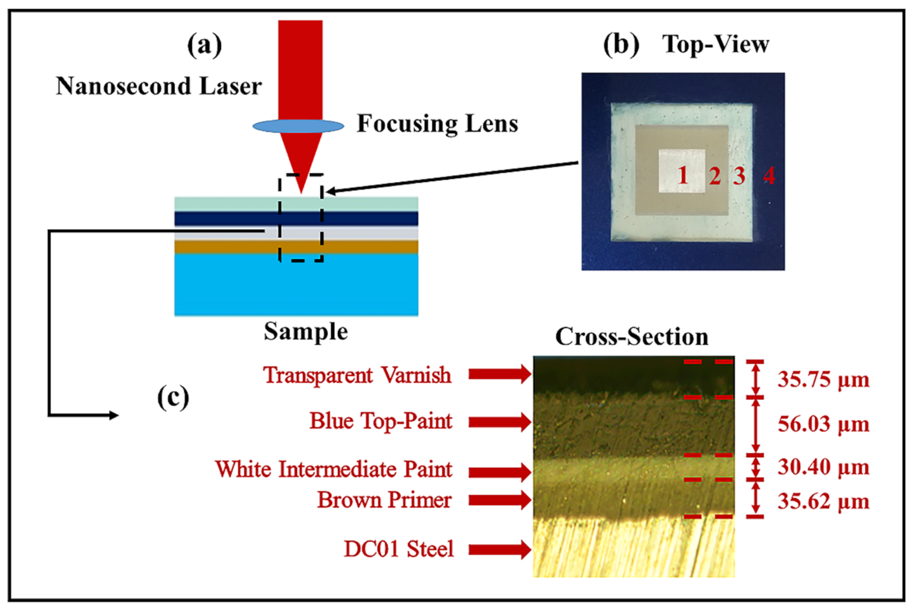
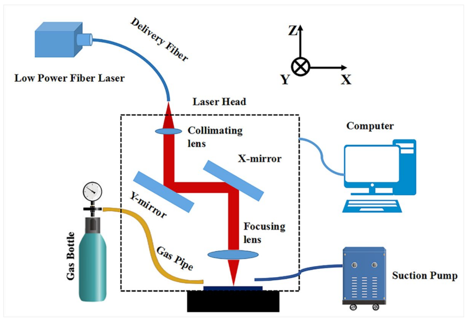
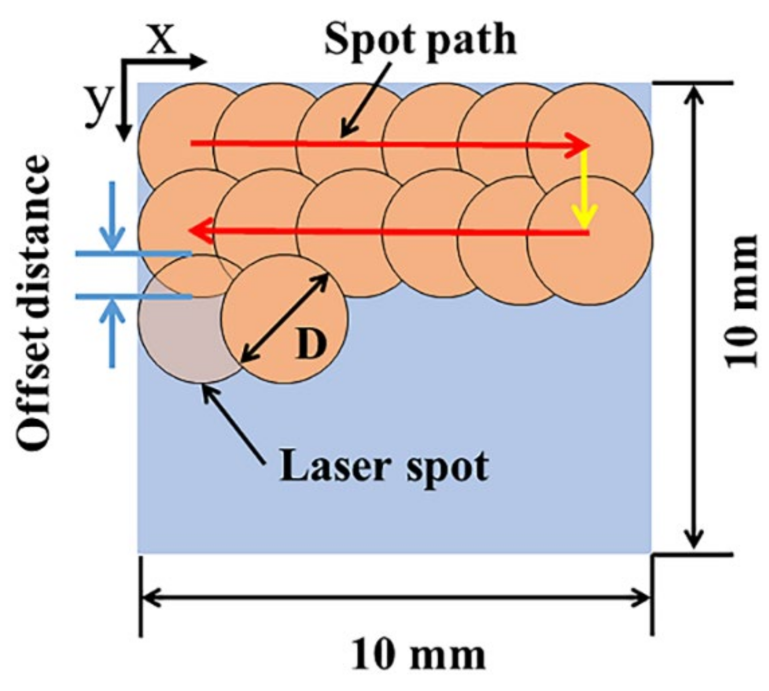
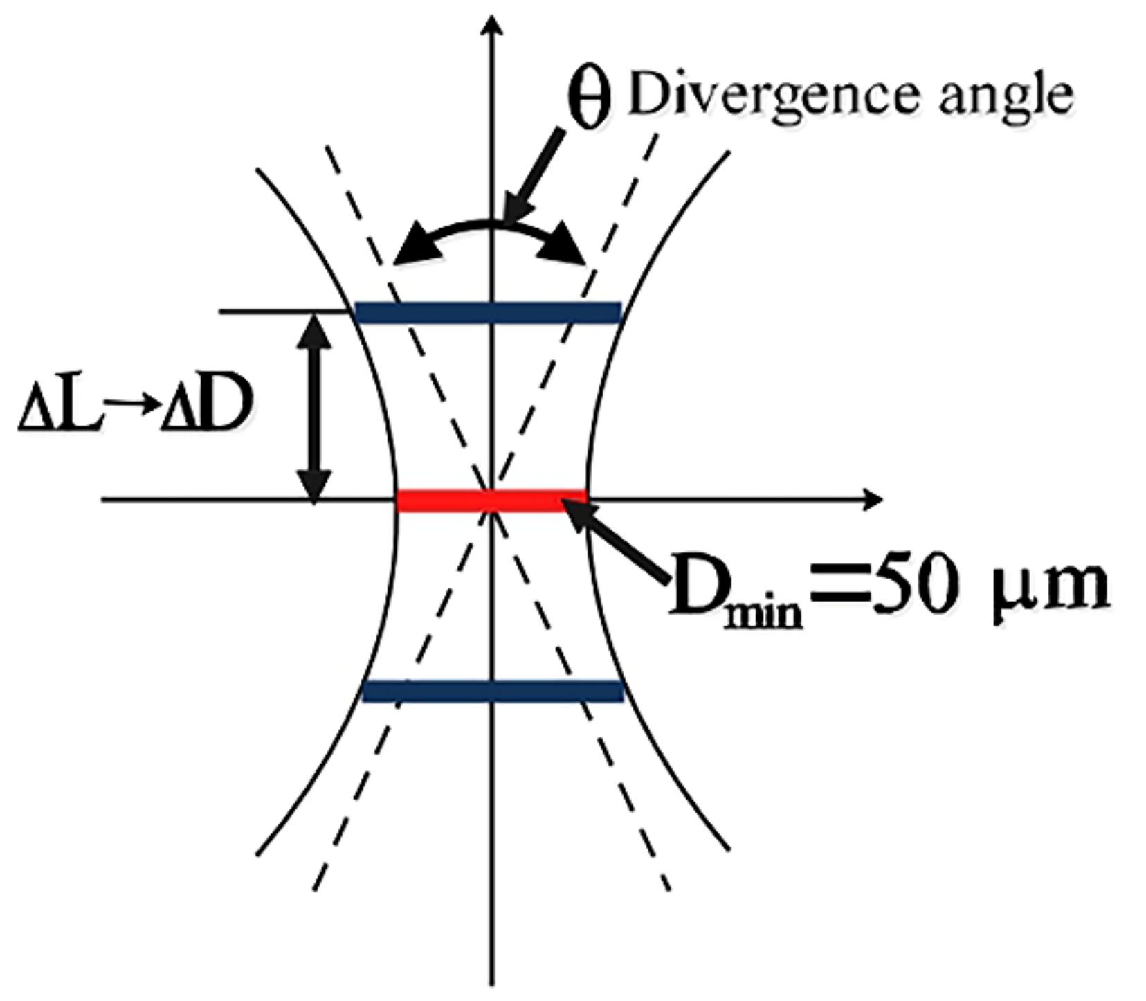
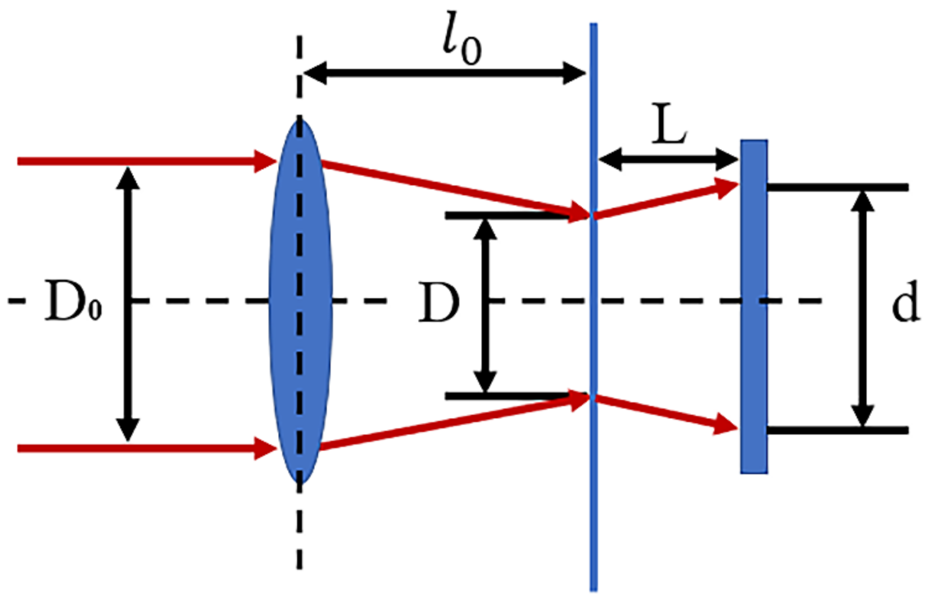
2.2. Laser Paint Removal
2.3. Characterisation and Tests
3. Results and Discussion
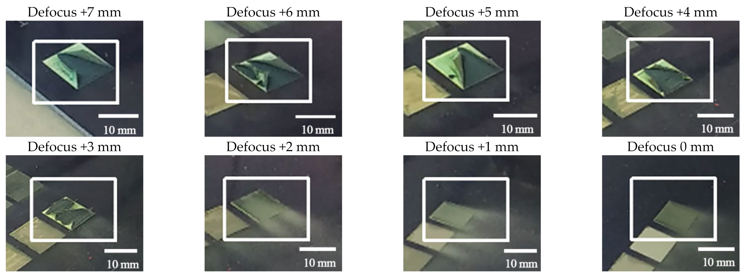
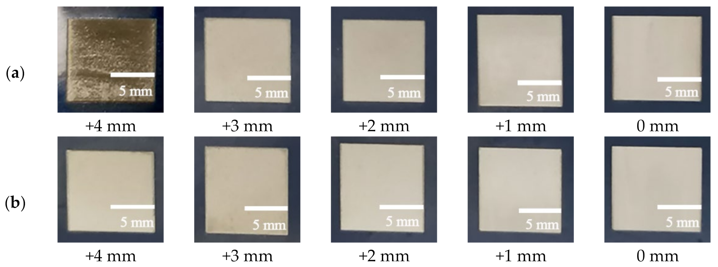
3.1. Macroscopic Phenomenon
3.2. Paint Removal Effect
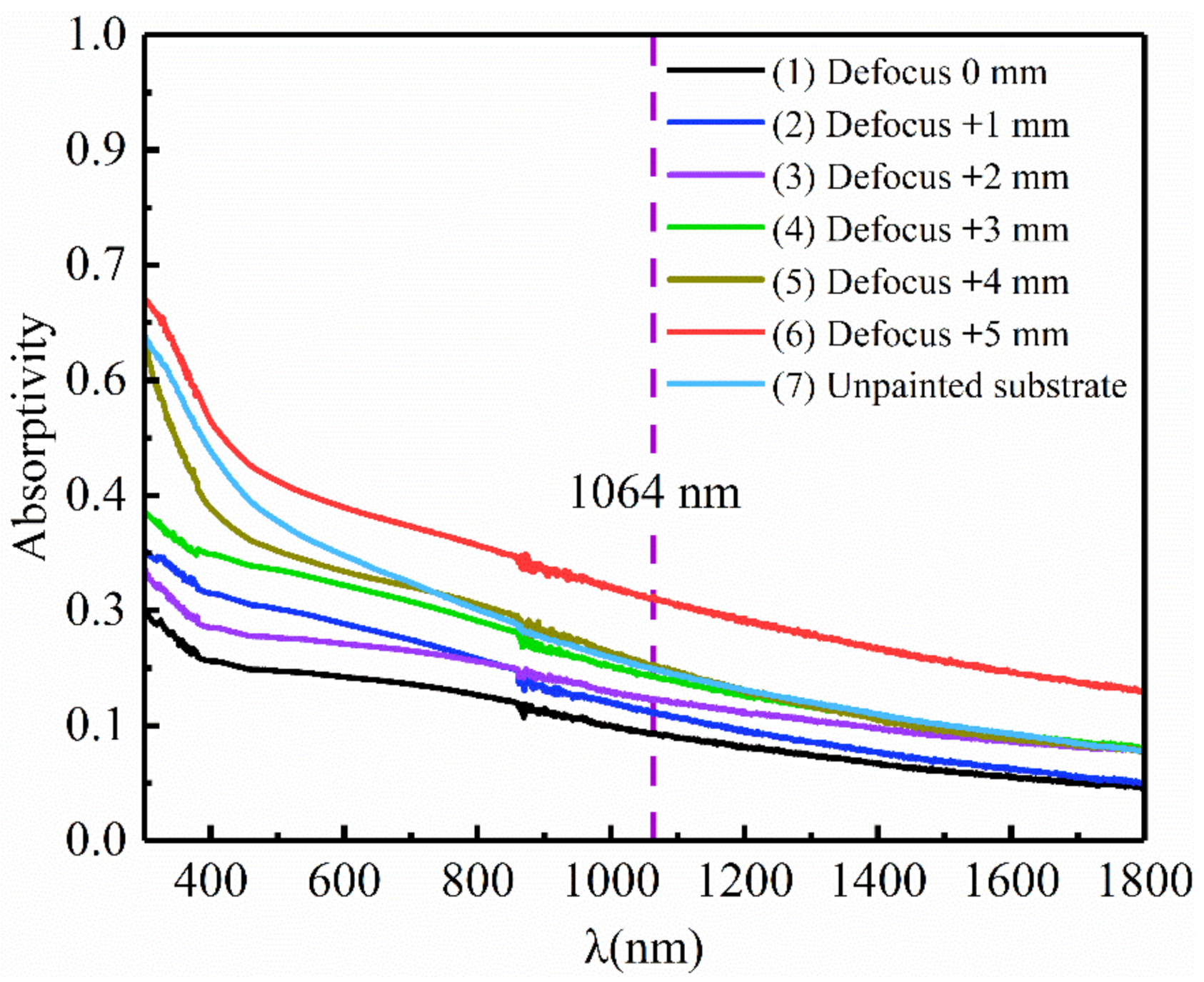
3.3. Surface Absorptivity
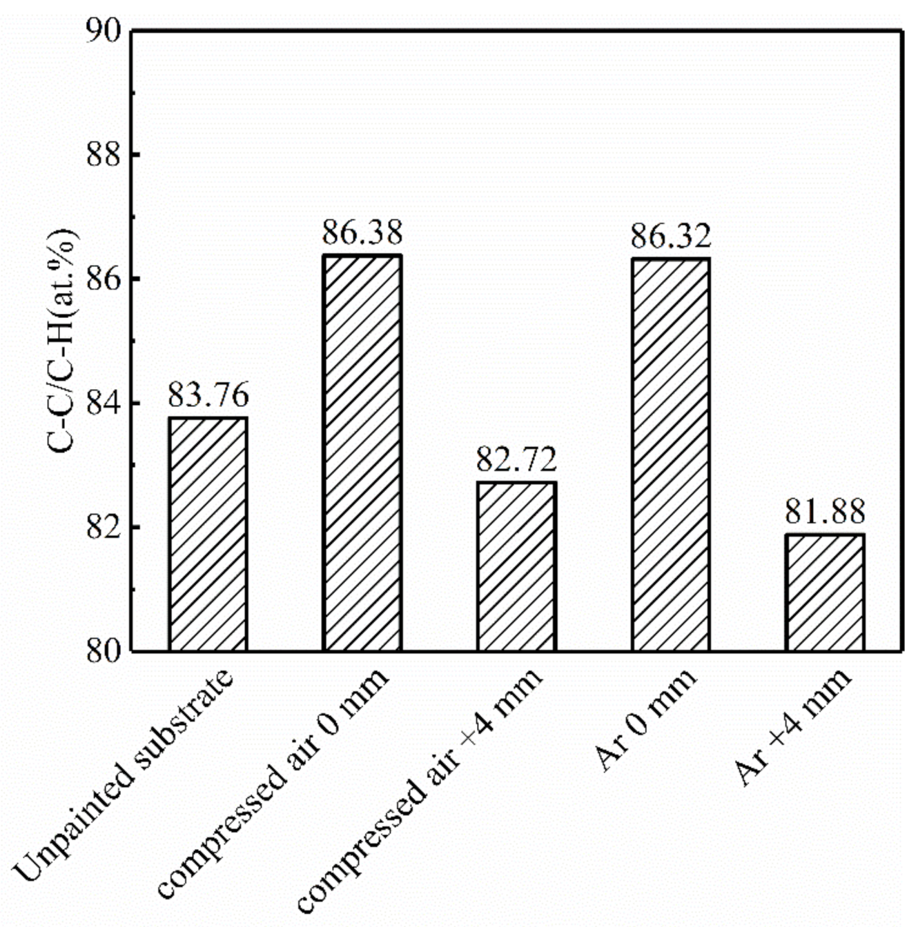
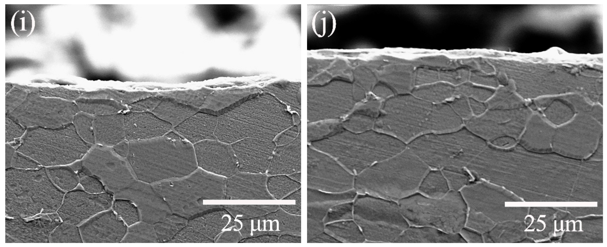
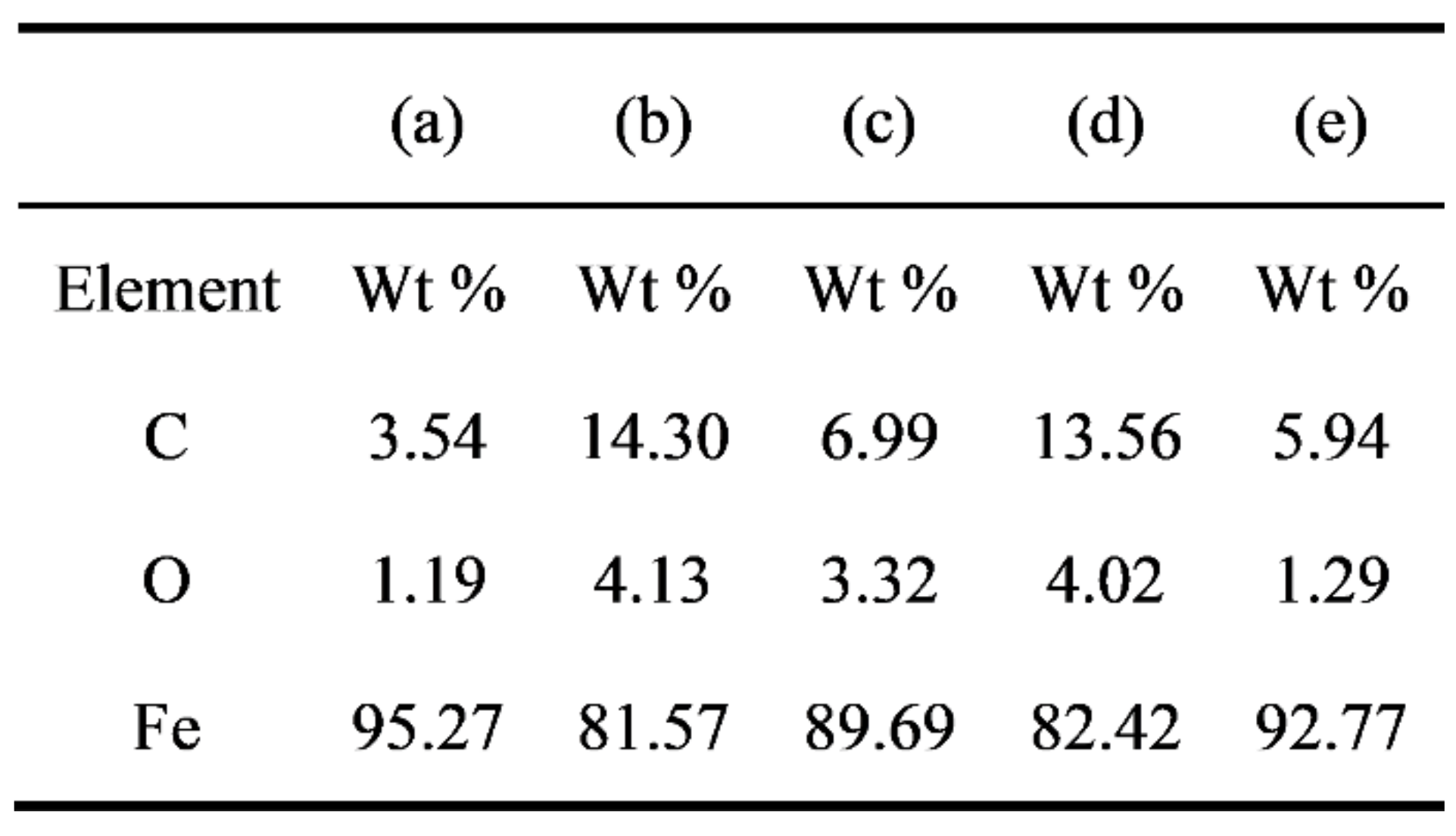
3.4. Characterization of Substrate
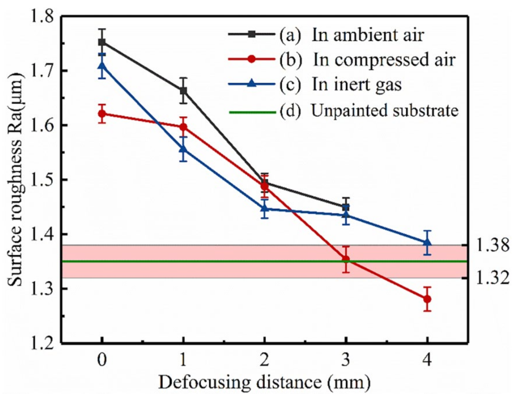
3.5. Roughness
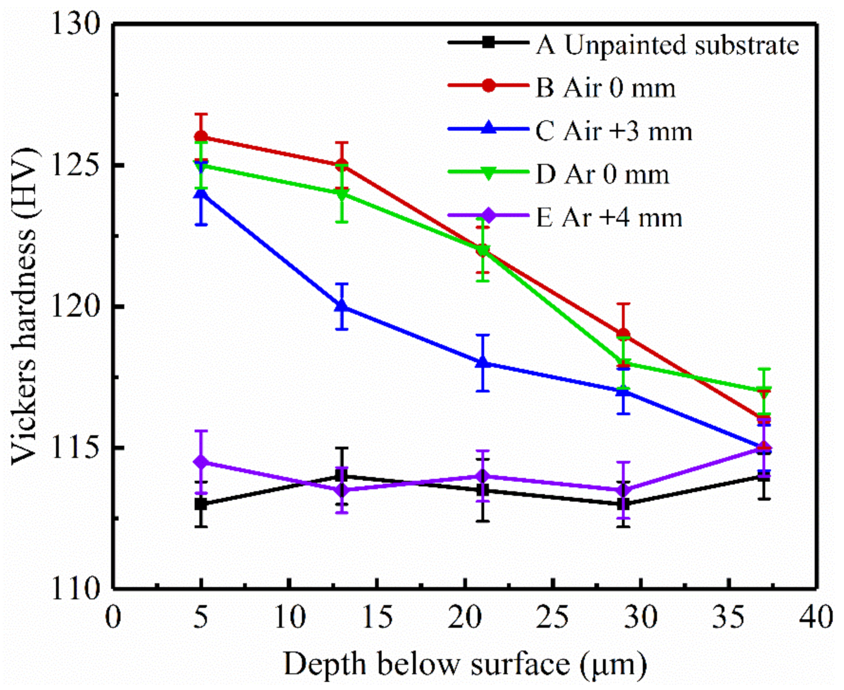
3.6. Microhardness
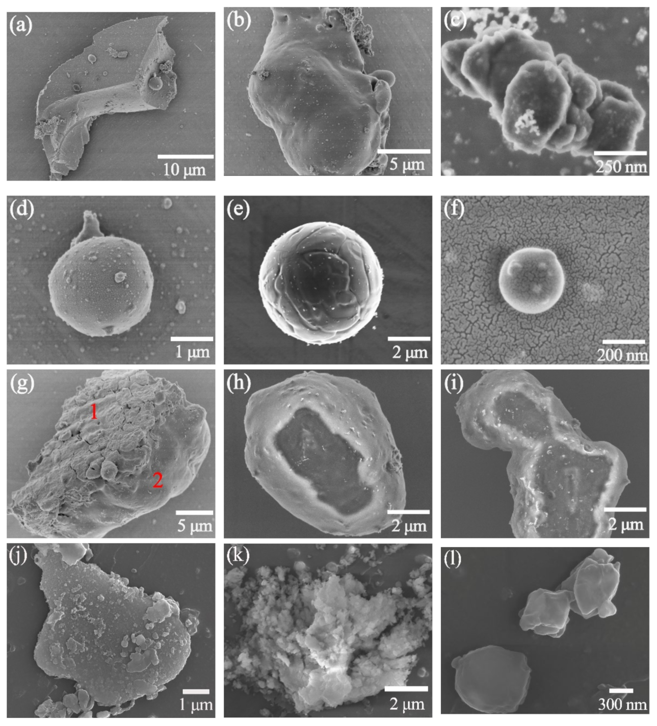
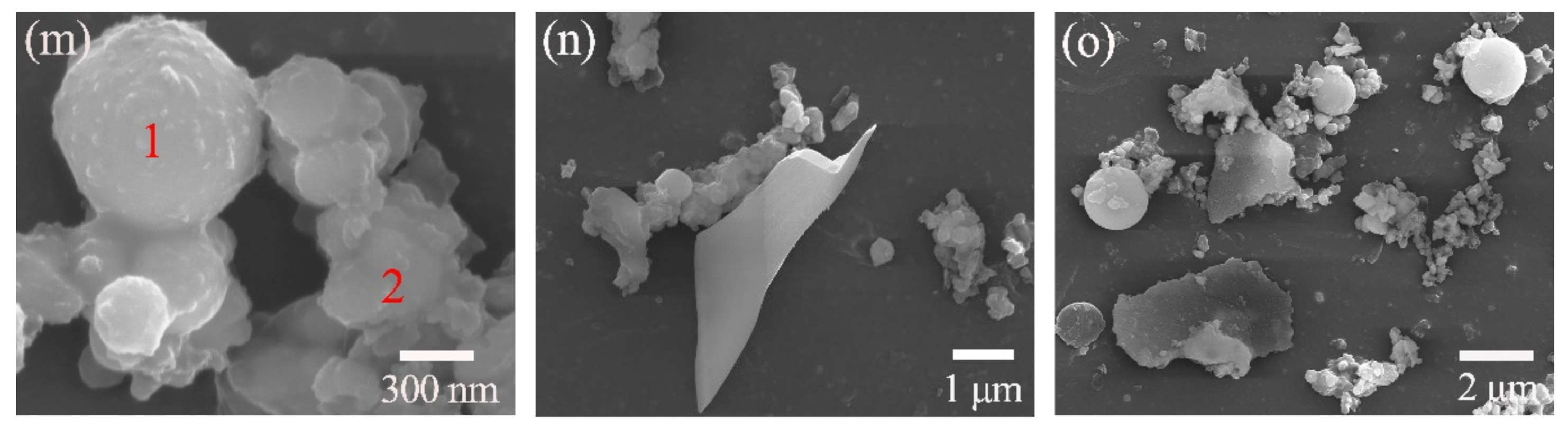
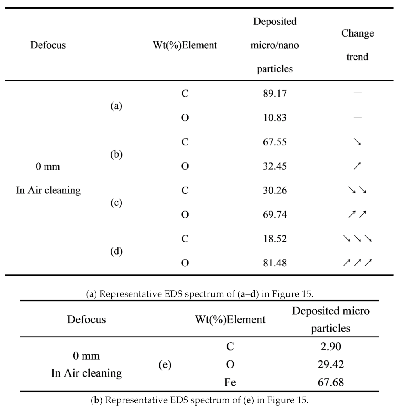
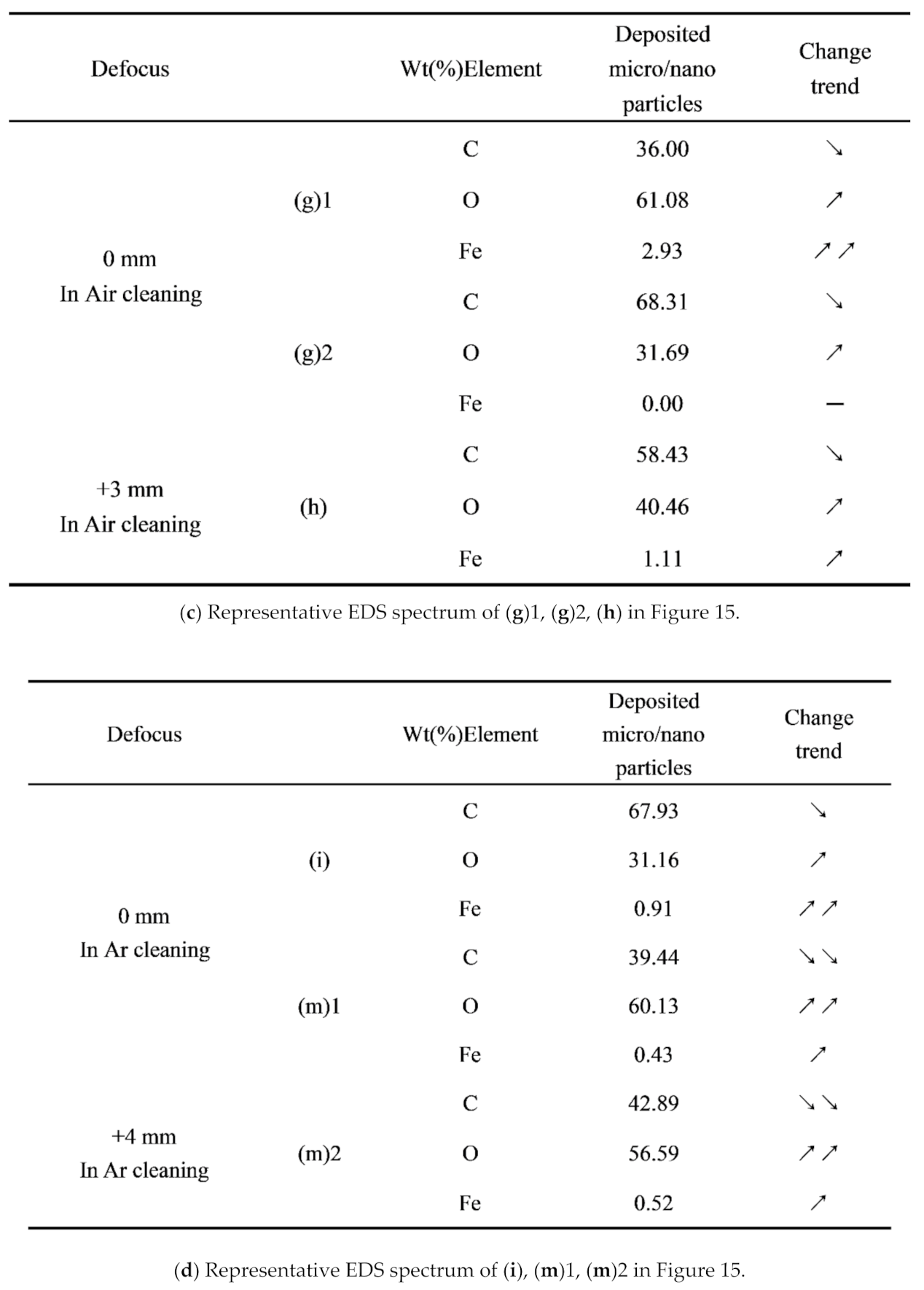
3.7. Characterization of Particles Collected on Silicon Wafers
4. Conclusions
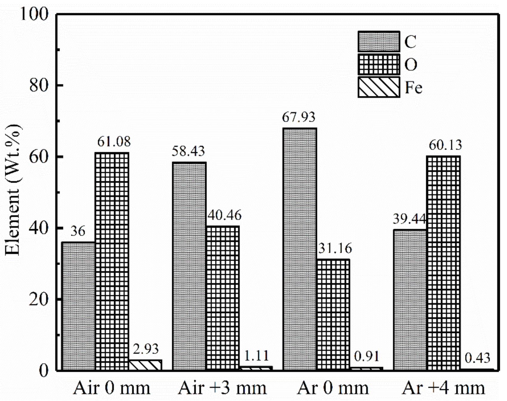
- The content of the C element and organic component in the samples laser treated (defocus distance +4 mm) in inert atmosphere was the lowest, and the organic component was reduced by 1.88% compared with the unpainted substrate. Their surface microtopography, roughness and hardness were very close to that of the unpainted substrate.
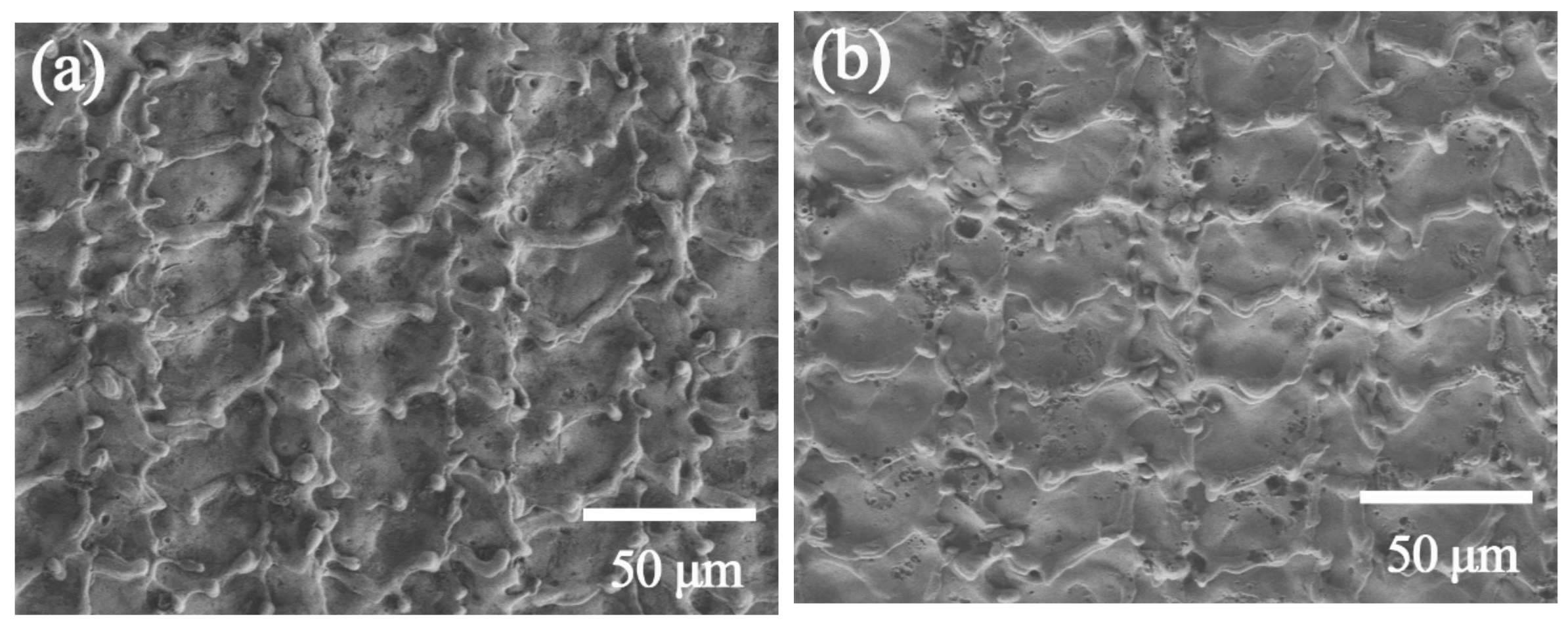
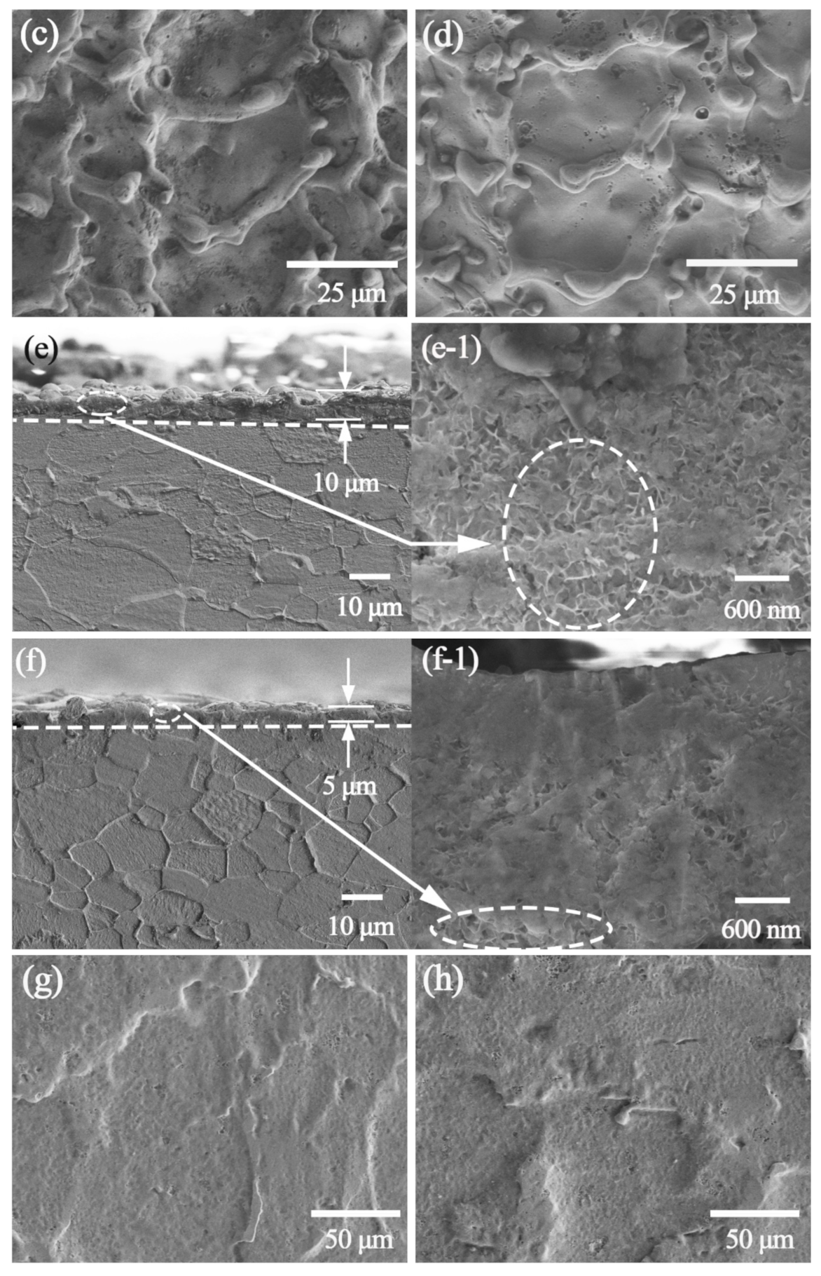
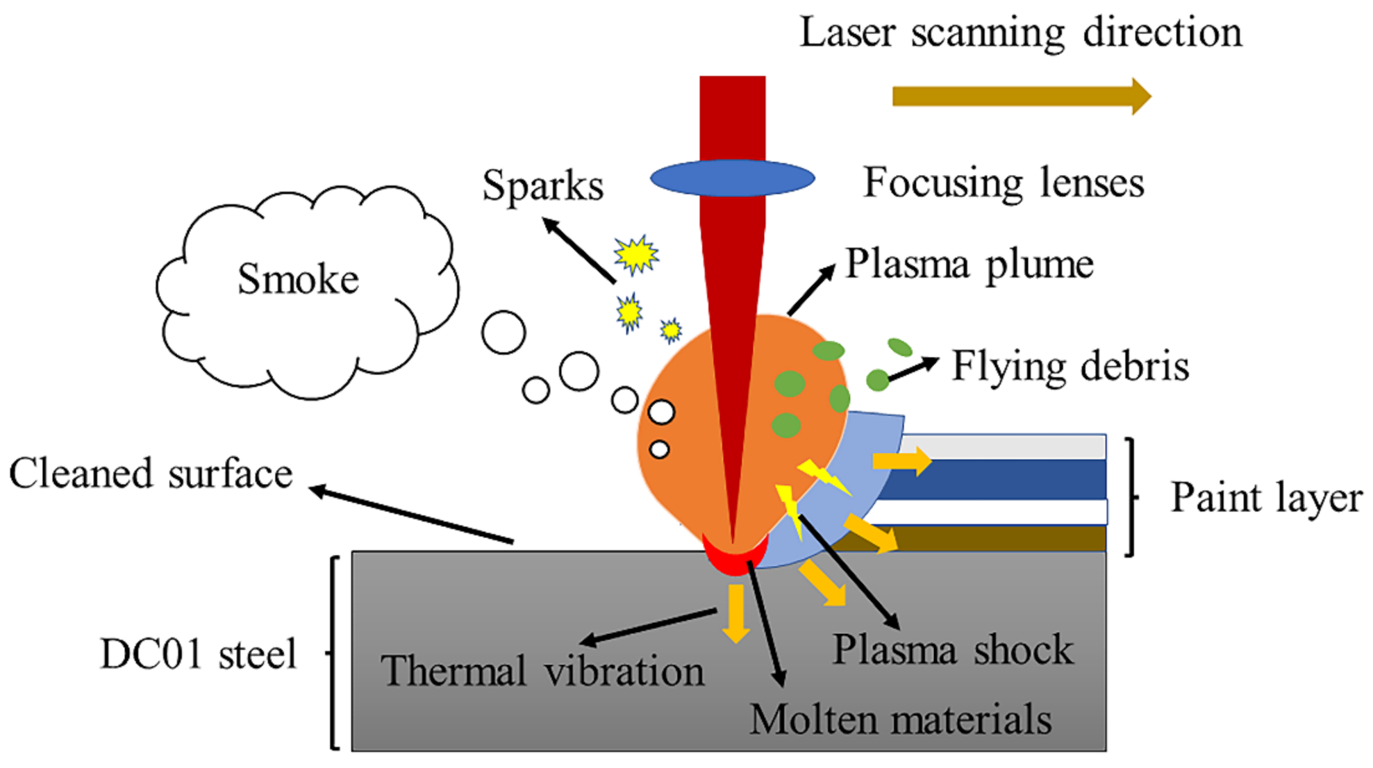
- With laser paint removal (in ambient air, defocusing distance 0 mm), the damage to the substrate is the most serious. The paint is removed at the focus of the laser; a remelted surface layer is formed on the surface of the substrate; the metallographic structure is changed; the crystal grains are refined, and the surface roughness is increased. The microhardness increases by more than 11 HV, and gradually decreases as the depth increases until it is 37 μm.
- In an open atmosphere (compressed air and inert gas, the gas flow is controlled at 8–10 Lpm) laser paint removal, only bright spots are seen when the paint layer is removed. Laser vaporization effects and thermal stress effects play a major role.
- In laser paint removal in an open atmosphere (compressed air and inert gas, the gas flow is controlled at 8–10 Lpm), the airflow can reduce local heat, make more energy act on the paint layer and accelerate the removal of the paint layer; by removing the ablation products, the generation of laser plasma and the shielding of the laser are avoided, and the damage of the substrate by the violent reaction is avoided. At the same time, the high-pressure gas blown during cleaning at the focal point can change the surface morphology and chemical composition content of the substrate, and the morphology and element content of the ablation product will also change.
Author Contributions
Funding
Institutional Review Board Statement
Informed Consent Statement
Data Availability Statement
Conflicts of Interest
References
- Lu, Y.F.; Takai, M.; Komuro, S.; Shiokawa, T.; Aoyagi, Y. Surface cleaning of metals by pulsed-laser irradiation in air. Appl. Phys. A 1994, 59, 281–288. [Google Scholar] [CrossRef]
- Schawlow, A.L. Lasers. Science 1965, 149, 13–22. [Google Scholar] [CrossRef]
- Bedair, S.M.; Smith, H.P. Atomically Clean Surfaces by Pulsed Laser Bombardment. J. Appl. Phys. 1969, 40, 4776–4781. [Google Scholar] [CrossRef]
- Siggs, E.B. Laser and Electron Beam Treatments for Corrosion Protection of Friction Stir Welds in Aerospace Alloys. Unpublished Ph.D. Thesis, University of Birmingha, Birmingha, UK, 2010. [Google Scholar]
- Razab, M.K.A.A.; Noor, A.A.M.; Jaafar, M.S.; Abdullah, N.H.; Suhaimi, F.M.; Mohamed, M.; Adam, N.; Yusuf, N.A.A.N. A review of incorporating Nd: YAG laser cleaning principal in automotive industry. J. Radiat. Res. Appl. Sci. 2019, 11, 393–402. [Google Scholar] [CrossRef] [Green Version]
- Lu, Y.; Yang, L.; Wang, Y.; Chen, H.; Guo, B.; Tian, Z. Paint Removal on the 5A06 Aluminum Alloy Using a Continuous Wave Fiber Laser. Coatings 2019, 9, 488. [Google Scholar] [CrossRef] [Green Version]
- Li, X.; Zhang, Q.; Zhou, X.; Zhu, D.; Liu, Q. The influence of nanosecond laser pulse energy density for paint removal. Optik 2018, 156, 841–846. [Google Scholar] [CrossRef]
- Kim, J.-E.; Song, M.-K.; Lee, J.-M.; Hyun, J.-H.; Kim, J.-D. Study on the Effect of Overlap Rate on Laser Beam Cleaning Characteristics while Cleaning Paint Using a Low Power Pulsed Laser (Ⅰ). J. Weld. Join. 2019, 37, 435–440. [Google Scholar] [CrossRef] [Green Version]
- Razab, M.K.A.A.; Jaafar, M.S.; Rahman, A.A.; Saidi, S.A. Identification of optimum operatives parameters for Pulse Nd: YAG laser in paint removal on different types of car coated substrate. Int. J. Educ. Res. 2014, 2, 1–18. [Google Scholar]
- Li, X.; Huang, T.; Zhou, R. Laser cleaning of steel structure surface for paint removal and repaint adhesion. Optoelectron. Eng. 2017, 44, 340–344. [Google Scholar]
- Kuang, Z.; Guo, W.; Li, J.; Jin, Y.; Qian, D.; Ouyang, J.; Fu, L.; Fearon, E.; Hardacre, R.; Liu, Z.; et al. Nanosecond fibre laser paint stripping with suppression of flames and sparks. J. Mater. Process. Technol. 2019, 266, 474–483. [Google Scholar] [CrossRef]
- Chen, G.X.; Kwee, T.J.; Tan, K.P.; Choo, Y.S.; Hong, M.H. Laser cleaning of steel for paint removal. Appl. Phys. A 2010, 101, 249–253. [Google Scholar] [CrossRef]
- Lu, Y.; Yang, L.; Wang, M.; Wang, Y. Simulation of nanosecond laser cleaning the paint based on the thermal stress. Optik 2021, 227, 165589. [Google Scholar] [CrossRef]
- Han, J.; Cui, X.; Wang, S.; Feng, G.; Deng, G.; Hu, R. Laser effects based optimal laser parameter identifications for paint removal from metal substrate at 1064 nm: A multi-pulse model. J. Mod. Opt. 2017, 64, 1947–1959. [Google Scholar] [CrossRef]
- Zhao, H.; Qiao, Y.; Du, X.; Wang, S.; Zhang, Q.; Zang, Y.; Liu, X. Laser cleaning performance and mechanism in stripping of Polyacrylate resin paint. Appl. Phys. A 2020, 126, 1–14. [Google Scholar] [CrossRef]
- Jasim, H.A.; Demir, A.G.; Previtali, B.; Taha, Z.A. Process development and monitoring in stripping of a highly transparent polymeric paint with ns-pulsed fiber laser. Opt. Laser Technol. 2017, 93, 60–66. [Google Scholar] [CrossRef]
- Razab, M.K.A.A.; Jaafar, M.S.; Rahman, A.A. A Study of Temperature Effects on Car Coated Substrate in Laser Paint Removal. Int. J. Eng. Technol. IJET-IJENS 2014, 14, 39–48. [Google Scholar]
- Razab, M.K.A.A.; Jaafar, M.S.; Abdullah, N.H.; Amin, M.F.M.; Mazlan, M. Surface morphology study in laser paint removal mechanisms on selected national car coated substrate. ARPN J. Eng. Appl. Sci. 2016, 11, 1819–6608. [Google Scholar]
- Shamsujjoha, M.; Agnew, S.R.; Melia, M.A.; Brooks, J.R.; Tyler, T.J.; Fitz-Gerald, J.M. Effects of laser ablation coating removal (LACR) on a steel substrate: Part 1: Surface profile, microstructure, hardness, and adhesion. Surf. Coat. Technol. 2015, 281, 193–205. [Google Scholar] [CrossRef]
- Shamsujjoha, M.; Agnew, S.R.; Brooks, J.R.; Tyler, T.J.; Fitz-Gerald, J.M. Effects of laser ablation coating removal (LACR) on a steel substrate: Part 2: Residual stress and fatigue. Surf. Coat. Technol. 2015, 281, 206–214. [Google Scholar] [CrossRef]
- Zhu, G.; Wang, S.; Cheng, W.; Ren, Y.; Wen, D. Corrosion and wear performance of aircraft skin after laser cleaning. Opt. Laser Technol. 2020, 132, 106475. [Google Scholar] [CrossRef]
- Li, J. Laser Cladding Technology and Application; Chemical Industry Press: Beijing, China, 2016; pp. 242–278. [Google Scholar]
- Marquardt, B.J.; Goode, S.R.; Angel, S.M. In Situ Determination of Lead in Paint by Laser-Induced Breakdown Spectroscopy Using a Fiber-Optic Probe. Anal. Chem. 1996, 68, 977–981. [Google Scholar] [CrossRef]
- Arif, A.F.M. Effect of input variability on the quality of laser shock processing. J. Mech. Sci. Technol. 2009, 23, 2603–2611. [Google Scholar] [CrossRef]
- Avetissian, H.K.; Ghazaryan, A.G.; Mkrtchian, G.F. Relativistic theory of inverse-bremsstrahlung absorption of ultrastrong laser radiation in plasma. J. Phys. B At. Mol. Opt. Phys. 2013, 46, 1–9. [Google Scholar] [CrossRef]
- Amoruso, S. Modeling of UV pulsed-laser ablation of metallic targets. Appl. Phys. 1999, 69, 323–332. [Google Scholar] [CrossRef]
- Kaganovich, D.; Gordon, D.F.; Helle, M.H.; Ting, A. Shaping gas jet plasma density profile by laser generated shock waves. J. Appl. Phys. 2014, 116, 13304. [Google Scholar] [CrossRef]
- Semak, V.; Matsunawa, A. The role of recoil pressure in energy balance during laser materials processing. J. Phys. D Appl. Phys. 1997, 30, 2541–2552. [Google Scholar] [CrossRef]
- Zou, W.-F.; Xie, Y.-M.; Xiao, X.; Zeng, X.-Z.; Luo, Y. Application of thermal stress model to paint removal by Q-switched Nd: YAG laser. Chin. Phys. B 2014, 23, 074205. [Google Scholar] [CrossRef]
- Zhao, H.; Qiao, Y.; Du, X.; Wang, S.; Zhang, Q.; Zang, Y. Pulse laser cleaning aluminum alloy surface paint Technical research of layer. China Laser 2021, 48, 0102001. [Google Scholar]
- Leone, C.; Genna, S.; Tagliaferri, F.; Palumbo, B.; Dix, M. Experimental investigation on laser milling of aluminium oxide using a 30W Q-switched Yb: YAG fiber laser. Opt. Laser Technol. 2016, 76, 127–137. [Google Scholar] [CrossRef]
- Zhao, H.; Qiao, Y.; Du, X.; Wang, S.; Zhang, Q.; Zang, Y.; Cai, Z. Paint Removal with Pulsed Laser: Theory Simulation and Mechanism Analysis. Appl. Sci. 2019, 9, 5500. [Google Scholar] [CrossRef] [Green Version]
- Shi, T.; Wang, C.; Mi, G.; Yan, F. A study of microstructure and mechanical properties of aluminum alloy using laser cleaning. J. Manuf. Process. 2019, 42, 60–66. [Google Scholar] [CrossRef]
- Wang, Z.; Zeng, X.; Huang, W. Parameters and surface performance of laser removal of rust layer on A3 steel. Surf. Coat. Tech. 2003, 166, 10–16. [Google Scholar] [CrossRef]
- Cui, Y.; Shen, J.; Hu, S. Microstructure and performance of the laser melted aluminum bronze layers with and without using activator. Mater. Res. Express 2019, 6, 066513. [Google Scholar] [CrossRef]
- Jiang, D.E.; Carter, E.A. Carbon dissolution and diffusion in ferrite and austenite from first principles. Phys. Rev. B 2003, 67, 214103. [Google Scholar] [CrossRef] [Green Version]
- Koch, J.; von Bohlen, A.; Hergenröder, R.; Niemax, K. Hergenröder, K. Niemax, Particle size distributions and compositions of aerosols produced by near-IR femto- and nanosecond laser ablation of brass. J. Anal. At. Spectrom. 2004, 19, 267–272. [Google Scholar] [CrossRef]
- Jafarabadi, M.A.; Mahdieh, M.H. Investigation of phase explosion in aluminum induced by nanosecond double pulse technique. Appl. Surf. Sci. 2015, 346, 263–269. [Google Scholar] [CrossRef]
- Groschel, A.H.; Walther, A.; Lobling, T.I.; Schacher, F.H.; Schmalz, H.; Muller, A.H. Guided hierarchical co-assembly of soft patchy nanoparticles. Nature 2013, 503, 247–251. [Google Scholar] [CrossRef]
- Vidal, F.; Johnston, T.W.; Laville, S.; Barthelemy, O.; Chaker, M.; Le Drogoff, B.; Margot, J.; Sabsabi, M. Critical-point phase separation in laser ablation of conductors. Phys. Rev. Lett. 2001, 86, 2573–2576. [Google Scholar] [CrossRef]
- Zheng, Z.Y.; Zhang, S.Q.; Liang, T.; Tang, W.C.; Xiao, K.; Liang, W.F.; Gao, L.; Gao, H.; Xing, J.; Wu, X.W.; et al. Characterization of laser ablation of carbon-doped glycerol at different laser wavelengths. Appl. Phys. A 2016, 122, 1062. [Google Scholar] [CrossRef]


| Paint Layers | Varnish | Colored Paint | Intermediate-Paint | Primer |
|---|---|---|---|---|
| Resin | Acrylic resin | Acrylic resin | Acrylic resin | Epoxy |
| Solvent | Aromatic hydrocarbons, Esters | Aromatic hydrocarbons, Esters | Aromatic hydrocarbons, Esters | Aromatic hydrocarbons, Esters |
| Additive | Leveling agent, Ehickener, Light stabilizer, etc. | Leveling agent, Dispersant, Light stabilizer, etc. | Leveling agent, Dispersant, Light stabilizer, etc. | Leveling agent, Dispersant, Light stabilizer, etc. |
| Pigment | None | Blue organic | Rutile titanium | Black organic |
| Colour | Transparent | Blue | White | Brown |
| vaporization temperature (°C) | 108–144 | >100 | 108–202 | 100 |
| Characteristic | Value | Units |
|---|---|---|
| Wavelength | 1064 | nm |
| Maximum repetition frequency | 1000 | KHz |
| Maximum scanning speed | 20,000 | mm/s |
| Maximum average power | 100 | W |
| Maximum pulse energy | >1.0 | mJ |
| Maximum peak power | >6 | KW |
| Pulse width range | 12–500 | ns |
| Beam diameter | 7.5 | mm |
| M2 (Beam quality factor) | ≤1.6 | – |
| Laser Pass | Pulse Repetition Frequency (KHz) | Scan Speed (mm/s) | Spot Overlap Rate (%) | Pulse Width (ns) | Energy Density (J/cm2) |
|---|---|---|---|---|---|
| 1st. | 463 | 9260 | 60 | 100 | 10.9 |
| 2nd. | 463 | 9260 | 60 | 100 | 10.9 |
| 3rd. | 536 | 13,400 | 50 | 100 | 9.5 |
| Defocus Distance (mm) | Scan Times | 0 | +1 | +2 | +3 | +4 | +5 | +6 | +7 |
|---|---|---|---|---|---|---|---|---|---|
| Spot diameter (mm) | - | 0.05 | 0.079 | 0.109 | 0.138 | 0.167 | 0.197 | 0.226 | 0.255 |
| Fluence (J/cm2) | 1st 2nd | 10.90 | 4.41 | 2.31 | 1.44 | 0.99 | 0.71 | 0.54 | 0.42 |
| 3rd | 9.51 | 3.81 | 2.00 | 1.25 | 0.85 | 0.61 | 0.47 | 0.37 |
| Atmosphere | Defocus Distance (mm) | Plasma | Debris Splash | Smoke | Flame | Dazzling Spot |
|---|---|---|---|---|---|---|
| air | 0–+4 | Yes | Yes | Yes | Yes | No |
| air | +5–+7 | No | No | No | Yes | No |
| Compressed air | 0–+7 | No | No | No | No | Yes |
| Inert gas | 0–+7 | No | No | No | No | Yes |
| Unpainted Substrate | Defocus 0 mm | Defocus +1 mm | Defocus +2 mm | Defocus +3 mm | Defocus +4 mm | Defocus +5 mm |
|---|---|---|---|---|---|---|
| 0.212 | 0.133 | 0.159 | 0.176 | 0.204 | 0.218 | 0.303 |
Publisher’s Note: MDPI stays neutral with regard to jurisdictional claims in published maps and institutional affiliations. |
© 2021 by the authors. Licensee MDPI, Basel, Switzerland. This article is an open access article distributed under the terms and conditions of the Creative Commons Attribution (CC BY) license (https://creativecommons.org/licenses/by/4.0/).
Share and Cite
Zheng, Z.; Wang, C.; Huang, G.; Feng, W.; Liu, D. Effect of Defocused Nanosecond Laser Paint Removal on Mild Steel Substrate in Ambient Atmosphere. Materials 2021, 14, 5969. https://doi.org/10.3390/ma14205969
Zheng Z, Wang C, Huang G, Feng W, Liu D. Effect of Defocused Nanosecond Laser Paint Removal on Mild Steel Substrate in Ambient Atmosphere. Materials. 2021; 14(20):5969. https://doi.org/10.3390/ma14205969
Chicago/Turabian StyleZheng, Zhong, Chaofan Wang, Gang Huang, Wenju Feng, and Dun Liu. 2021. "Effect of Defocused Nanosecond Laser Paint Removal on Mild Steel Substrate in Ambient Atmosphere" Materials 14, no. 20: 5969. https://doi.org/10.3390/ma14205969
APA StyleZheng, Z., Wang, C., Huang, G., Feng, W., & Liu, D. (2021). Effect of Defocused Nanosecond Laser Paint Removal on Mild Steel Substrate in Ambient Atmosphere. Materials, 14(20), 5969. https://doi.org/10.3390/ma14205969