
Selective Laser Melting of Stainless Steel 316L with Face-Centered-Cubic-Based Lattice Structures to Produce Rib Implants


Abstract
:1. Introduction
2. Materials and Methods
2.1. Materials
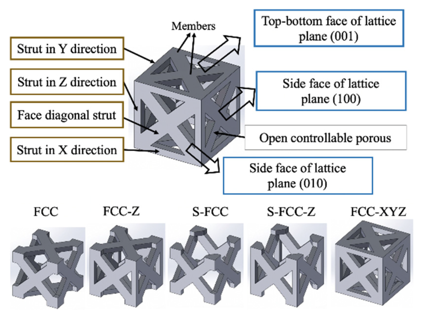
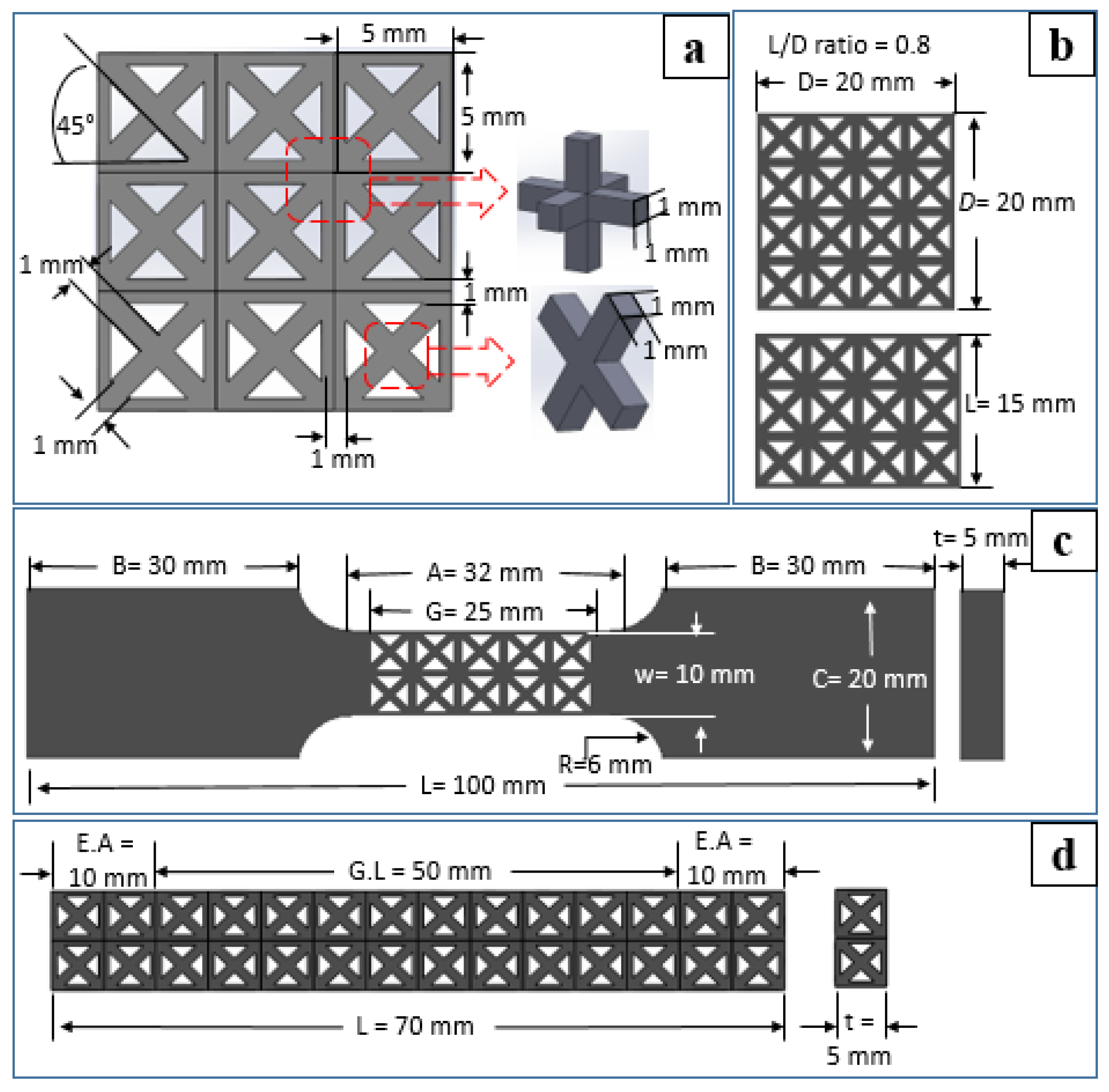
2.2. Lattice Design
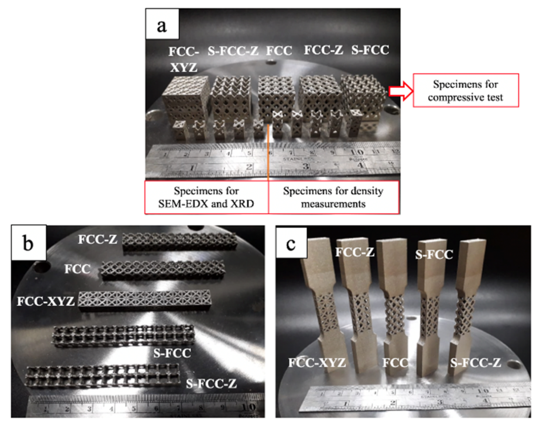
2.3. Lattice Production
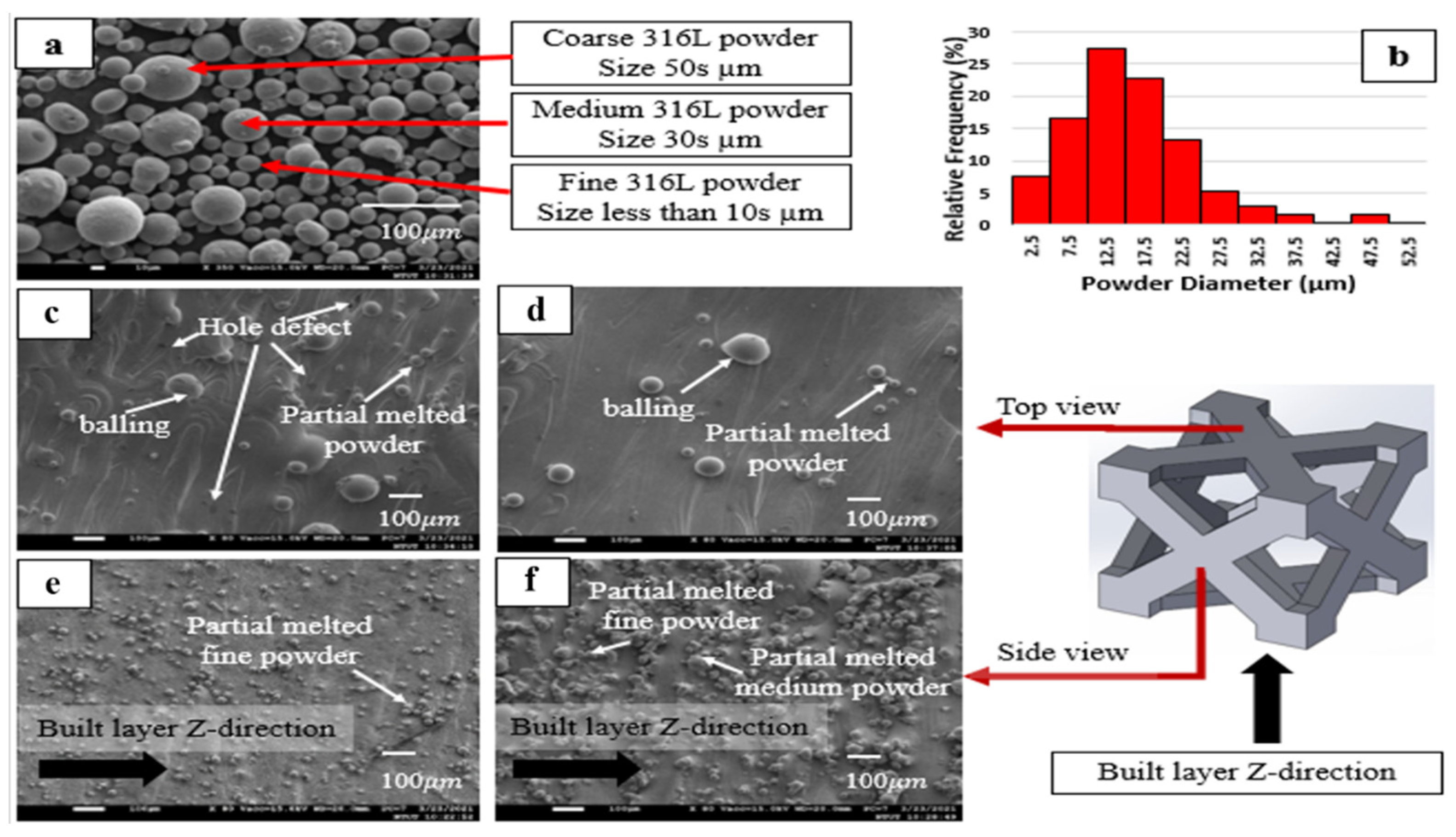
2.4. Characterization of the Lattice Surface Morphology and the Chemical Composition
2.5. Density
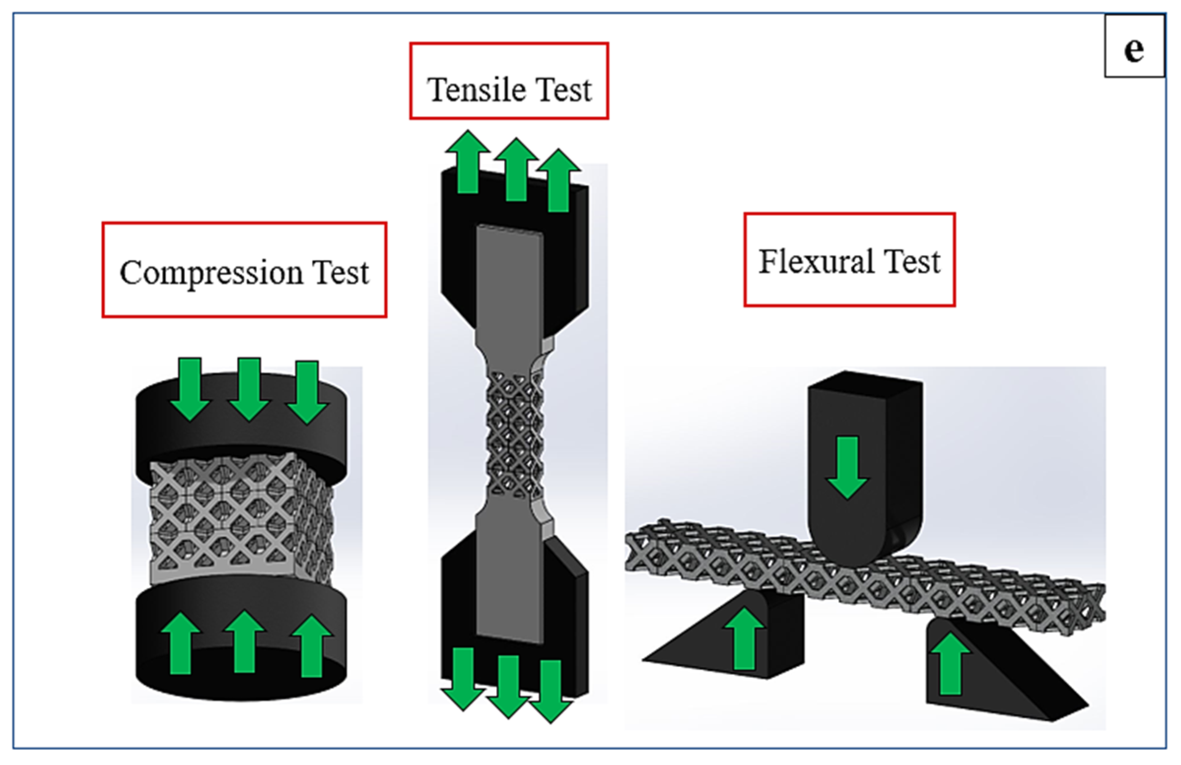
2.6. Mechanical Testing
3. Results and Discussion
3.1. Lattice Production
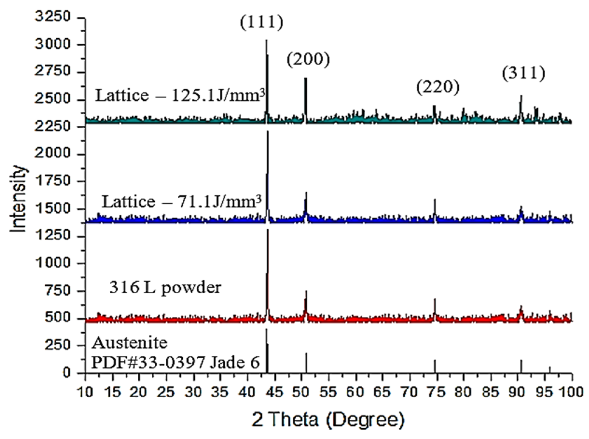
3.2. Surface Morphology and Chemical Analysis of the Lattice
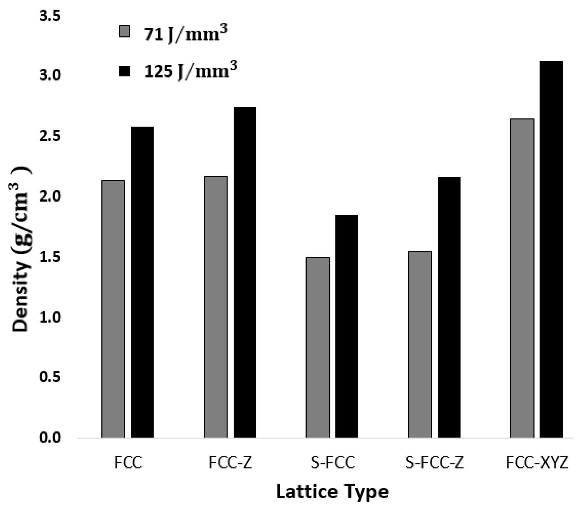
3.3. Density Measurement
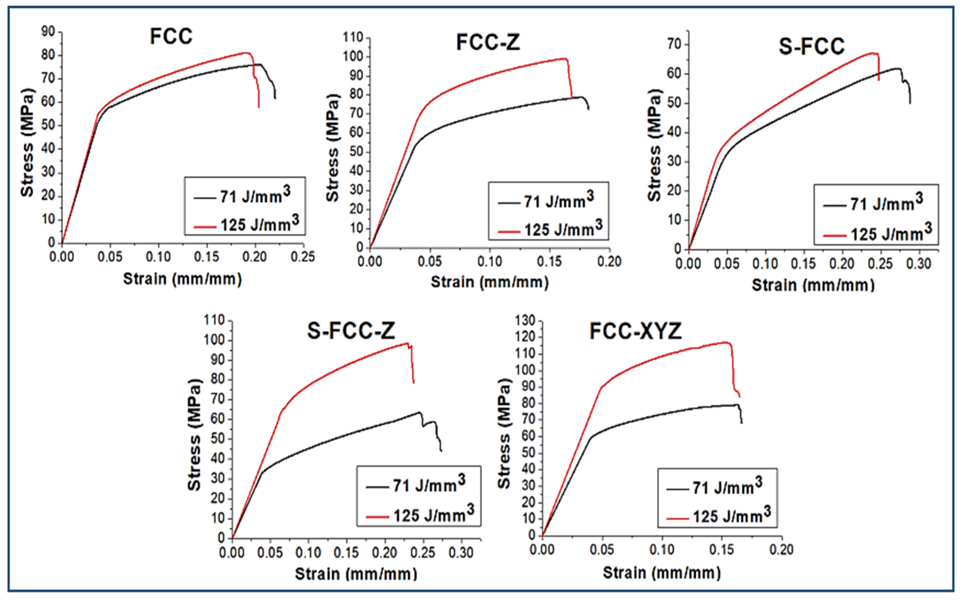
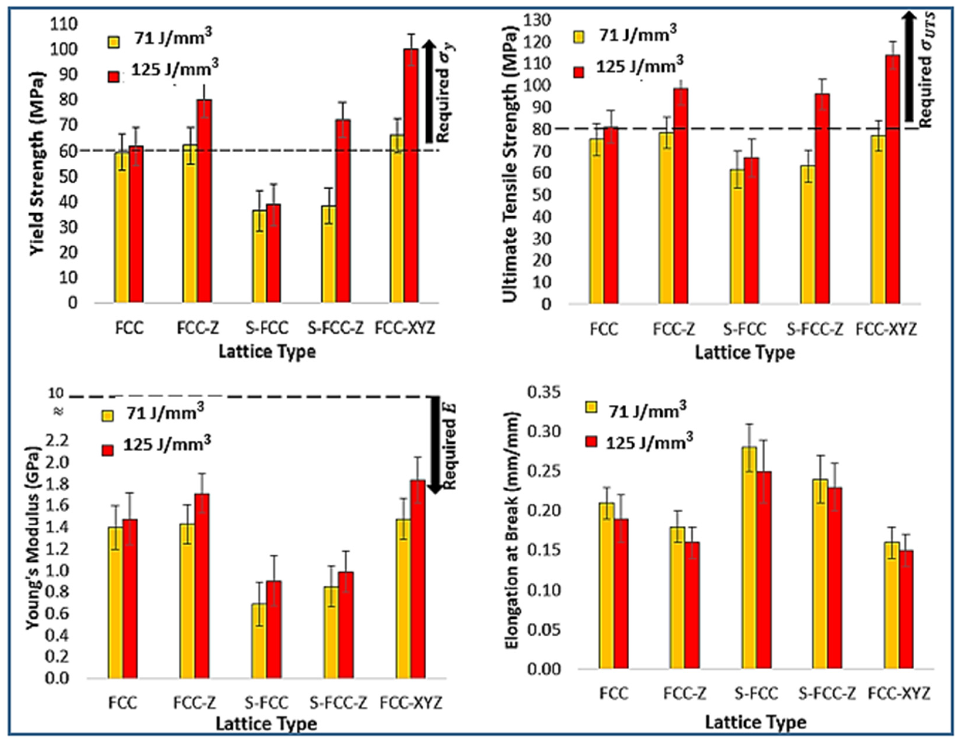
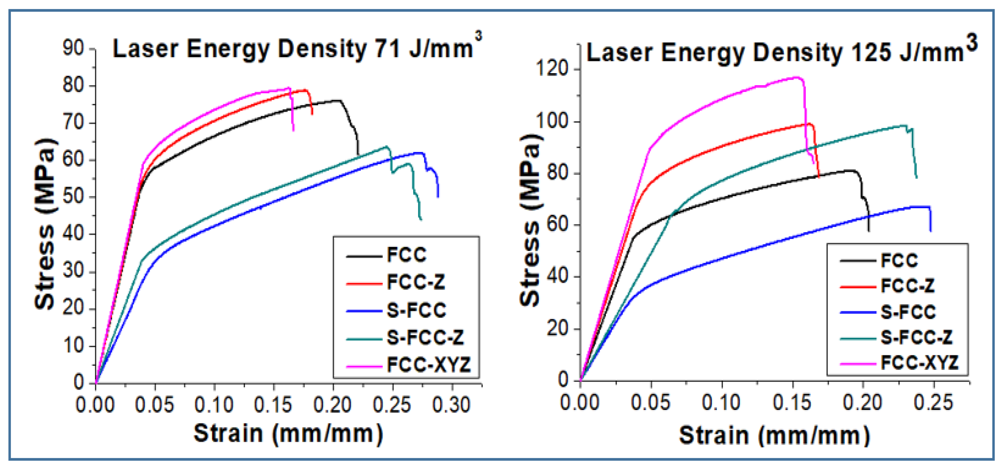
3.4. Tensile Properties
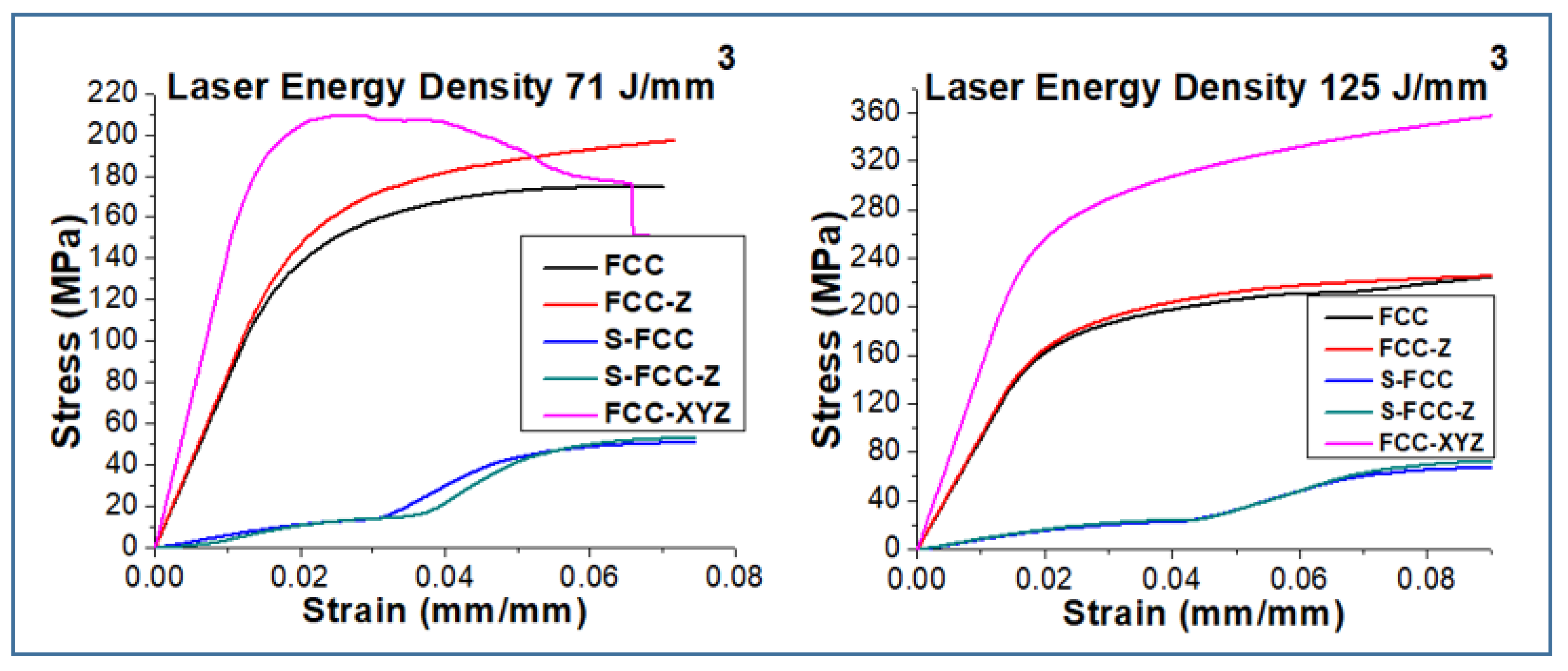
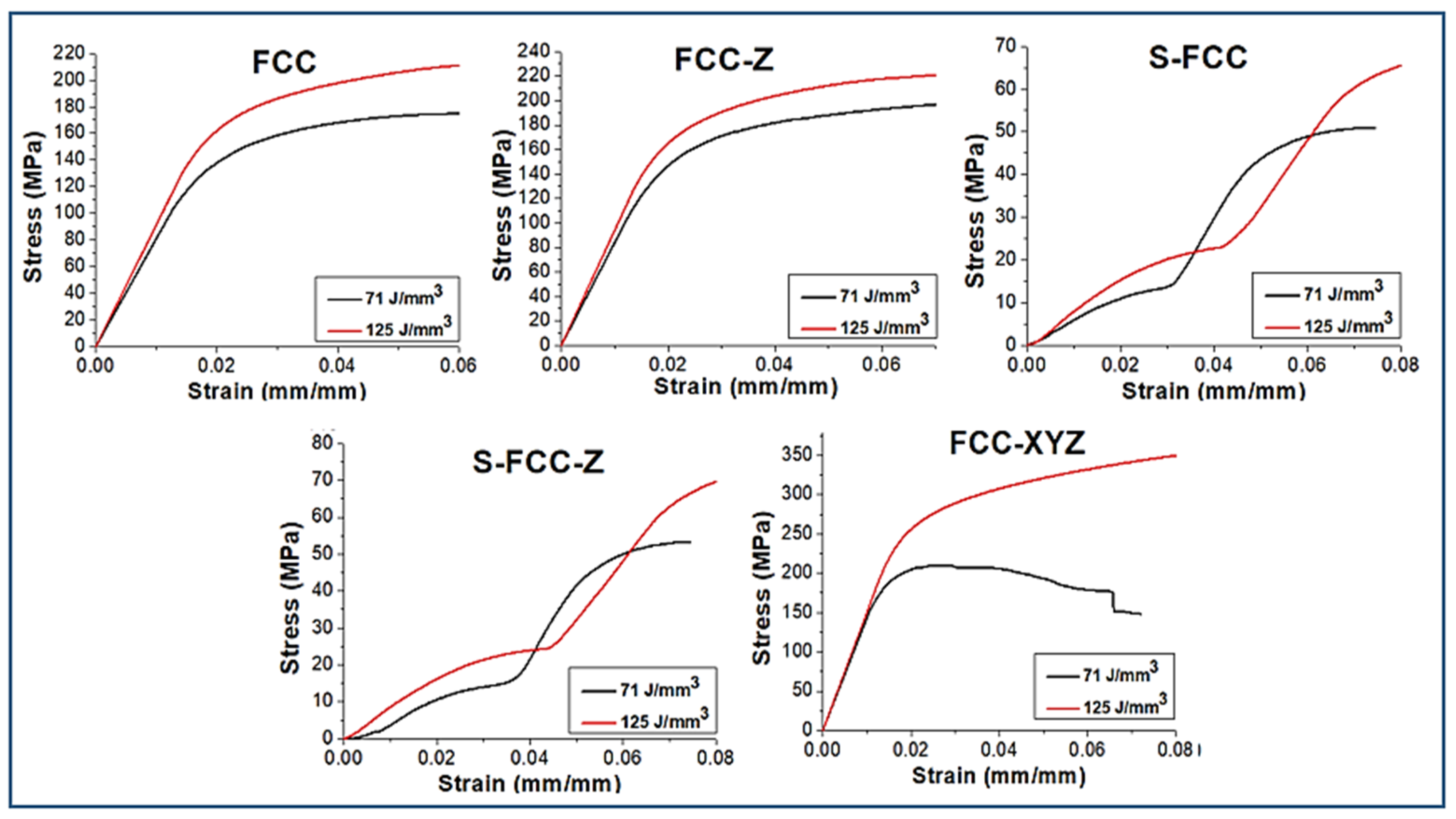
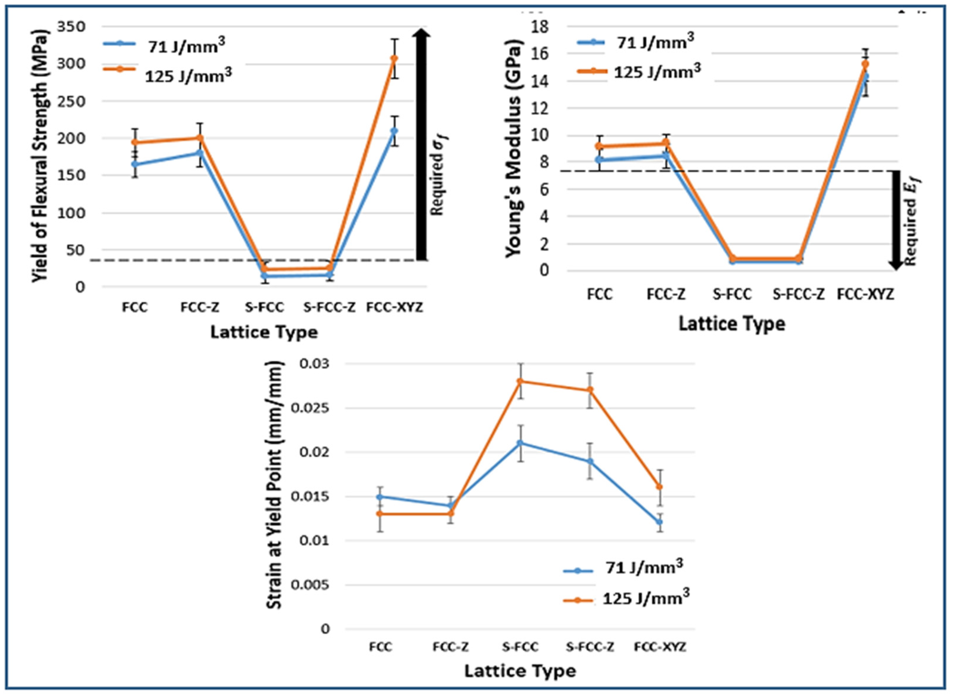
3.5. Flexural Properties
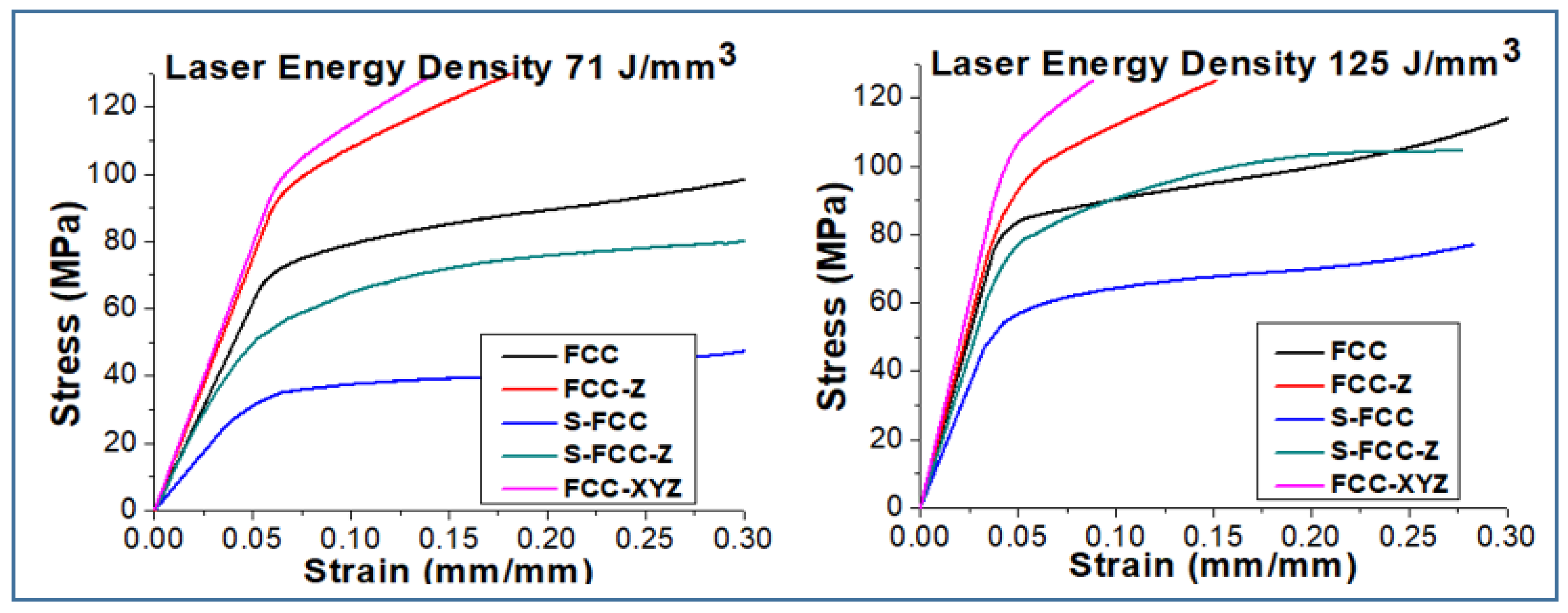
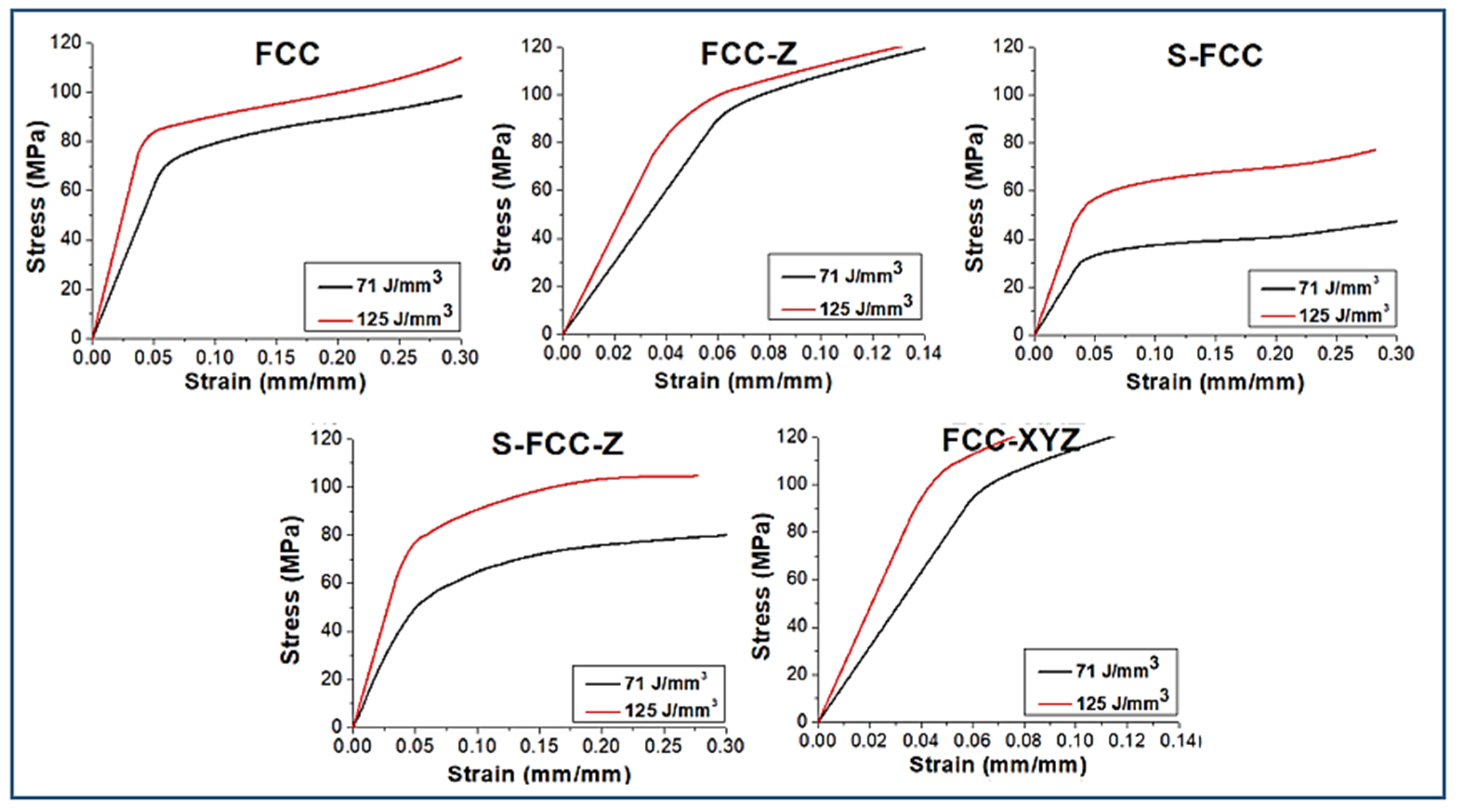
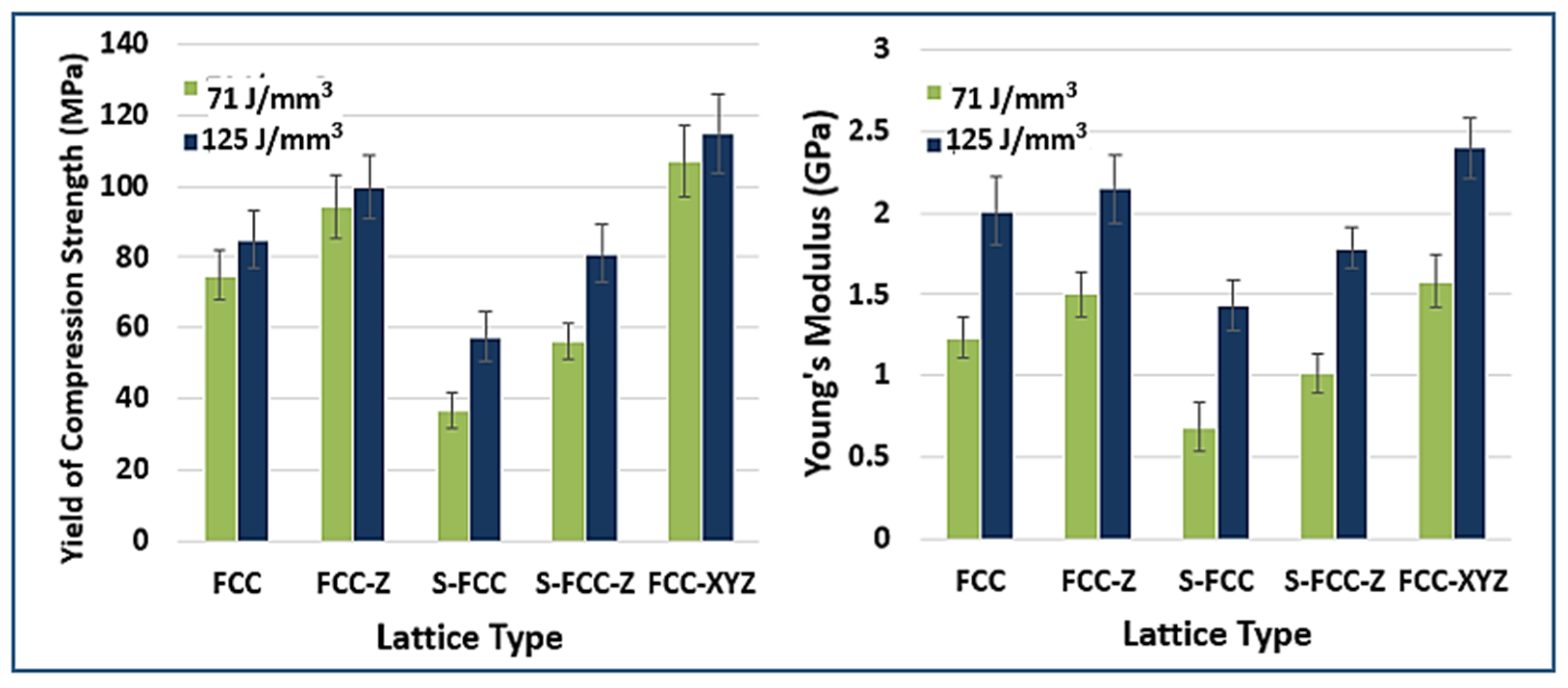
3.6. Compression Properties
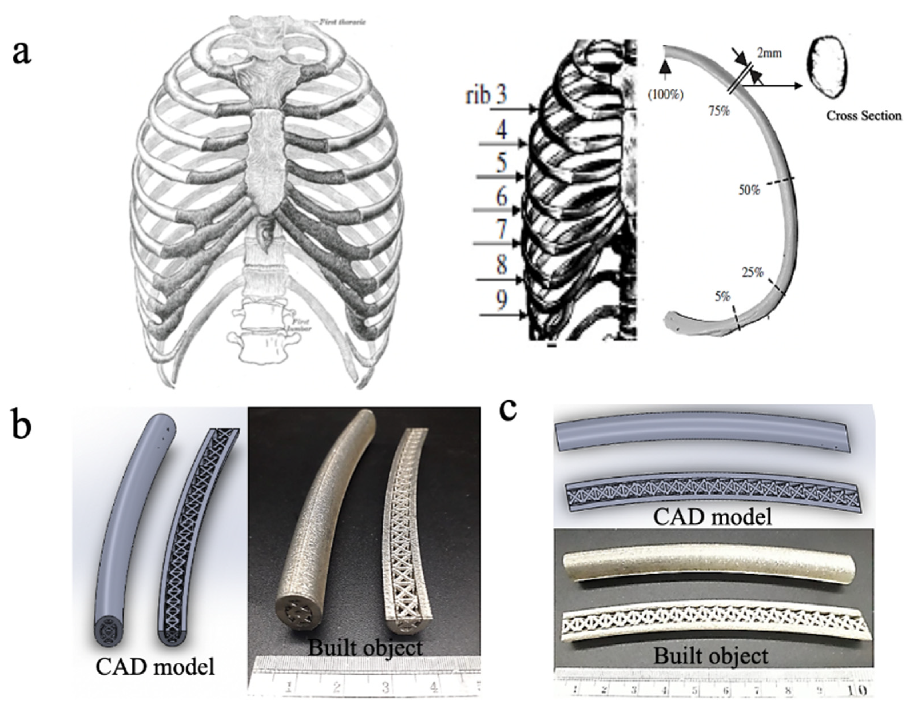
3.7. The Prototype of Lattice in Rib Implant Application
4. Conclusions
Author Contributions
Funding
Institutional Review Board Statement
Informed Consent Statement
Data Availability Statement
Acknowledgments
Conflicts of Interest
References
- Feuer, G.; Saha, S. Effect of Deformation Rate on the Flexural Strength of Human Ribs. In Proceedings of the 2012 38th Annual Northeast Bioengineering Conference (NEBEC), Philadelphia, PA, USA, 16–18 March 2012; pp. 137–138. [Google Scholar]
- Zhang, J.; Hong, Q.; Mo, X.; Ma, C. Complete video-assisted thoracoscopic surgery for rib fracture: A series of 35 cases. Ann. Thorac. Surg. 2021, 21, 00356–00358. [Google Scholar]
- Khan, W.S.; Agarwal, M.; Malik, A.A.; Cox, A.G.; Denton, J.; Holt, E.M. Chromium, cobalt and titanium metallosis involving a Nottingham shoulder replacement. J. Bone Jt. Surg. Br. 2008, 90, 502–505. [Google Scholar] [CrossRef] [PubMed]
- Sivaraj, D.; Vijayalakshmi, K. Novel synthesis of bioactive hydroxyapatite/f-multiwalled carbon nanotube composite coating on 316L SS implant for substantial corrosion resistance and antibacterial activity. J. Alloys Compd. 2019, 777, 1340–1346. [Google Scholar] [CrossRef]
- Mi, Z.R.; Shuib, S.; Hassan, A.Y.; Shorki, A.A.; Ibrahim, M.M. Problem of stress shielding and improvement to the hip implant design: A Review. J. Med. Sci. 2007, 7, 460–467. [Google Scholar]
- Guilherme, L.H.; Benedetti, A.V.; Fugivara, C.S.; Magnabosco, R.; Oliveira, M.F. Effect of MAG welding transfer mode on sigma phase precipitation and corrosion performance of 316L stainless steel. J. Mater. Res. Technol. 2020, 9, 10537–10549. [Google Scholar] [CrossRef]
- Sui, G.; Charles, E.A.; Congleton, J. The effect of delta ferrite content on the stress corrosion cracking of austenite stainless steel in a sulphate solution. Corros. Sci. 1996, 38, 687–703. [Google Scholar] [CrossRef]
- Tsai, S.-P.; Makineni, S.K.; Gault, B.; Kawano-Miyata, K.; Taniyama, A.; Zaefferer, S. Precipitation formation on Ʃ5 and Ʃ7 grain boundaries in 316L stainless steel and their roles on intergranular corrosion. Acta Mater. 2021, 210, 116822. [Google Scholar] [CrossRef]
- Al-Rashidy, Z.M.; Farag, M.M.; Ghany, N.A.; Ibrahim, A.M.; Abdel-Fattah, W.I. Aquaeous electrophoretic deposition and corrosion protection of borate glass coating on 316L stainless steel for hard tissue fixation. Surf. Interfaces 2017, 7, 125–133. [Google Scholar] [CrossRef]
- Stockmann-Juvala, H.; Hedberg, Y.; Dhinsa, N.K.; Griffiths, D.R.; Brooks, P.N.; Zitting, A.; Wallinder, I.O.; Santonen, T. Inhalation toxicity of 316L stainless steel powder in relation to bioaccessibility. Hum. Exp. Toxicol. 2013, 32, 1137–1154. [Google Scholar] [CrossRef]
- Cao, X.; Xiao, D.; Li, Y.; Wen, W.; Zhao, T.; Chen, Z.; Jiang, Y. Dynamic compressive behaviour of a modified additively manufactured rhombic dodecahedron 316L stainless steel lattice structure. Thin-Walled Struct. 2020, 148, 106586. [Google Scholar] [CrossRef]
- Yan, C.; Hao, L.; Hussein, A.; Young, P.; Raymont, D. Advanced lightweight 316L stainless steel cellular lattice structures fabricated via selective laser melting. Mater. Des. 2014, 55, 533–541. [Google Scholar] [CrossRef] [Green Version]
- Zhong, T.; He, K.; Li, H.; Yang, L. Mechanical properties of lightweight 316L stainless steel lattice structure fabricated by selective laser melting. Mater. Des. 2019, 181, 108076. [Google Scholar] [CrossRef]
- Zhu, Y.; Fang, Y.; Bermond, F.; Bruyere-Garnier, K.; Ellouz, R.; Rongieras, F.; Mitton, D. Relationship between human rib mechanical properties and cortical bone density by high-resolution computed tomography. Comput. Methods Biomech. Biomed. Eng. 2013, 16, 191–192. [Google Scholar] [CrossRef] [PubMed]
- Elise, F.M.; Ginu, U.U.; Amira, I.H. Bone Mechanical Properties in Healthy and Diseased States. Annu. Rev. Biomed. Eng. 2018, 20, 119–143. [Google Scholar]
- Katzenberger, M.J.; Albert, D.L.; Agnew, A.M.; Kemper, A.R. Effect of sex, age and two loading rates on the tensile material properties of human rib cortical bone. J. Mech. Behav. Biomed. Mater. 2020, 102, 103410. [Google Scholar] [CrossRef] [PubMed]
- John, B. Manufacture, characterization and application of cellular metals and metal foams. Prog. Mater. Sci. 2001, 46, 559–632. [Google Scholar]
- De Wild, M.; Zimmermann, S.; Rüegg, J.; Schumacher, R.; Fleischmann, T.; Ghayor, C.; Weber, F.E. Influence of Microarchitecture on Osteoconduction and Mechanics of porous Titanium Scaffolds Generated by Selective Laser Melting. 3D Print. Addit. Manuf. 2016, 3, 143–151. [Google Scholar] [CrossRef]
- Mostafa, Y.; Elbestawi, M.A.; Stephen, C.V. Density and mechanical properties in selective laser melting of Invar 36 and stainless steel 316L. J. Mater. Process. 2019, 266, 397–420. [Google Scholar]
- Tsopanos, S.; Mines, R.A.W.; McKown, S.; Shen, Y.; Cantwell, W.J.; Brooks, W.; Sutcliffe, C.J. The Influence of Processing Parameters on the Mechanical Properties of Selectively Laser Melted Stainless Steel Microlattice Structures. J. Manuf. Sci. Eng. 2010, 132, 041011. [Google Scholar] [CrossRef]
- Mostafa, Y.; Elbestawi, M.A.; Stephen, C.V. A study of thermal expansion coefficients and microstructure during selective laser melting of Invar 36 and stainless steel 316L. Addit. Manuf. 2018, 24, 405–418. [Google Scholar]
- Larimian, T.; Kannan, M.; Grzesiak, D.; AlMangour, B.; Borkar, T. Effect of energy density and scanning strategy on densification, microstructure and mechanical properties of 316L stainless steel processed via selective laser melting. Mater. Sci. Eng. A 2020, 770, 1308455. [Google Scholar] [CrossRef]
- Rottger, A.; Boes, J.; Theisen, W. Microstructure and mechanical properties of 316L austenitic stainless steel processed by different SLM devices. Int. J. Adv. Manuf. Technol. 2020, 108, 769–783. [Google Scholar] [CrossRef]
- Liu, J.; Song, Y.; Chen, C.; Wang, X.; Li, H.; Wang, J.; Guo, K.; Sun, J. Effect of scanning speed on the microstructure and mechanical behavior of 316L stainless steel fabricated by selective laser melting. Mater. Des. 2020, 186, 108355. [Google Scholar] [CrossRef]
- Olaf, R.; Claus, E. Rapid manufacturing of lattice structures with selective laser melting. In Laser-Based Micropackaging; International Society for Optics and Photonics: Bellingham, WA, USA, 2006; Volume 6107, p. 61070K. [Google Scholar]
- Albert, C.I.; Jameson, J.; Harris, G. Design and validation of bending test method for characterization of miniature pediatric cortical bone specimens. Proc. Inst. Mech. Eng. Part H J. Eng. Med. 2013, 227, 105–113. [Google Scholar] [CrossRef]
- Bourgette, D.T. Evaporation of Iron-, Nickel-, and Cobalt-Base Alloys at 7600 to 9800C in High Vacuums; ORNL-3677; Oak Ridge National Laboratory: Oak Ridge, TN, USA, 1964. [Google Scholar]
- Yong, H.S.; Chang, D.W. Examination of molten pool with Marangoni flow and evaporation effect by simulation and experiment in selective laser melting. Int. Commun. Heat Mass Transf. 2021, 125, 105325. [Google Scholar]
- Chen, X.; Li, J.; Cheng, X.; Wang, H.; Huang, Z. Effect of heat treatment on microstructure, mechanical properties and corrosion properties of austenitic stainless steel 316L using arc additive manufacturing. Mater. Sci. Eng. A 2018, 715, 307–314. [Google Scholar] [CrossRef]
- Montero-Sistiaga, M.L.; Godino-Martinez, M.; Boschmans, K.; Kruth, J.P.; Van Humbeeck, J.; Vanmeensel, K. Microstructure evolution of 316L produced by HP-SLM (high power selective laser melting). Addit. Manuf. 2018, 23, 402–410. [Google Scholar] [CrossRef]
- Fang, Z.C.; Wu, Z.L.; Huang, C.G.; Wu, C.W. Review on residual stress in selective laser melting additive manufacturing of alloy parts. Opt. Laser Technol. 2020, 129, 106283. [Google Scholar] [CrossRef]
- Zhang, L.; Song, B.; Choi, S.K.; Shi, Y. A topology strategy to reduce stress shielding of additively manufactured porous metallic biomaterials. Int. J. Mech. Sci. 2021, 197, 106331. [Google Scholar] [CrossRef]
- Wikipedia. Rib. 2021. Available online: https://en.wikipedia.org/w/index.php?title=Rib&oldid=1016425690 (accessed on 7 April 2021).
- Celina, P.; Maciej, G. The mechanical properties of human ribs in young adult. Acta Bioeng. Biomech. 2012, 14, 56–60. [Google Scholar]
- Mohr, M.; Abrams, E.; Engel, C.; Long, W.B.; Bottlang, M. Geometry of human ribs pertinent to orthopaedic chest-wall reconstruction. J. Biomech. 2007, 40, 1310–1317. [Google Scholar] [CrossRef] [PubMed]


| Human Rib Properties | Values | References |
|---|---|---|
| Density (ρ) | 0.736 g/cm3 | [14] |
| Flexural test | ||
| Young’s modulus () | 2.79~7.44 GPa | [1] |
| Strength () | 38.64~80.98 MPa | [15] |
| Tensile test | ||
| Young’s modulus (): | 10~17 GPa | [14,16] |
| Yielding strength (): | 60~100 MPa | [14,16] |
| Ultimate tensile strength () | 80~120 MPa | [14,16] |
| Lattice | Descriptions |
|---|---|
| FCC | Original lattice with diagonal struts arranged on all planes including (100), (010), and (001). |
| FCC-Z | Lattice with diagonal struts arranged on all planes and addition struts in the Z direction only. |
| S-FCC | Lattice with diagonal struts arranged on side planes (100) and (010) only |
| S-FCC-Z | Lattice with diagonal struts arranged on side planes (100) and (010) only and addition struts in the Z direction only. |
| FCC-XYZ | Lattice with diagonal struts arranged on all planes including (100), (010), and (001) and addition struts in the X, Y, and Z directions. |
| Sample | Chemical Composition (wt.%) | ||
|---|---|---|---|
| Cr | Ni | Fe | |
| Powder 316 L | 16.05 | 17.30 | 66.64 |
| FCC lattice—71.1 J/mm3 | 20.56 | 14.57 | 65.07 |
| FCC lattice—125.1 J/mm3 | 19.90 | 15.00 | 65.10 |
| Lattice Type | Density (g/cm3) | Volume Fraction | Relative Density (%) | Relative Porosity (%) | ||||
|---|---|---|---|---|---|---|---|---|
| L71 J/mm3 | L125 J/mm3 | L71 J/mm3 | L125 J/mm3 | L71 J/mm3 | L125 J/mm3 | L71 J/mm3 | L125 J/mm3 | |
| FCC | 2.1 | 2.6 | 0.267 | 0.323 | 26.7 | 32.3 | 73.3 | 67.7 |
| FCC-Z | 2.2 | 2.7 | 0.271 | 0.342 | 27.1 | 34.2 | 72.9 | 65.8 |
| S-FCC | 1.5 | 1.8 | 0.187 | 0.231 | 18.7 | 23.1 | 81.3 | 76.9 |
| S-FCC-Z | 1.6 | 2.2 | 0.193 | 0.271 | 19.3 | 27.1 | 80.7 | 72.9 |
| FCC-XYZ | 2.6 | 3.1 | 0.331 | 0.391 | 33.1 | 39.1 | 66.9 | 60.9 |
| Solid | 8 | Vbulk | 1 | 100 | 0 | |||
| LED | Lattice Type | Tensile Properties | Flexural Properties | Compression Properties | |||||||
|---|---|---|---|---|---|---|---|---|---|---|---|
| (Mpa) | (Mpa) | (Mpa) | (%) | (Mpa) | E (GPa) | (%) | (Mpa) | E (GPa) | (%) | ||
| 71 J/mm3 | FCC | 59.5 ± 7 | 75.3 ± 8 | 1.39 ± 0.26 | 21 ± 2 | 166 ± 17 | 8.09 ± 0.8 | 1.5 ± 0.1 | 74.8 ±7 | 1.2 ± 0.1 | 7.4 ± 1 |
| FCC-Z | 62.1 ± 7 | 78.3 ± 7 | 1.42 ± 0.18 | 18 ± 2 | 180 ± 19 | 8.39 ± 0.7 | 1.4 ± 0.1 | 94.3 ±9 | 1.5 ± 0.1 | 7.6 ± 1 | |
| S-FCC | 36.2 ± 8 | 61.5 ± 8 | 0.68 ± 0.22 | 28 ± 3 | 14 ± 9 | 0.63 ± 0.1 | 2.1 ± 0.2 | 36.6 ±5 | 0.7 ± 0.2 | 8.5 ± 2 | |
| S-FCC-Z | 38.3 ± 7 | 63.2 ± 7 | 0.85 ± 0.21 | 24 ± 3 | 16 ± 7 | 0.69 ± 0.1 | 1.9 ± 0.2 | 56.4 ±5 | 1.0 ± 0.1 | 8.3 ± 2 | |
| FCC-XYZ | 66.1 ± 7 | 76.9 ± 6 | 1.48 ± 0.19 | 16 ± 2 | 209 ± 21 | 14.29 ± 1.2 | 1.2 ± 0.1 | 107 ± 9 | 1.5 ± 0.2 | 8.1 ± 1 | |
| 125 J/mm3 | FCC | 61.8 ± 7 | 80.9 ± 7 | 1.47 ± 0.18 | 19 ± 3 | 194 ± 19 | 9.13 ± 0.8 | 1.3 ± 0.2 | 84.9 ± 8 | 2.0 ± 0.2 | 5.3 ± 1 |
| FCC-Z | 80.4 ± 7 | 98.7 ± 7 | 1.71 ± 0.17 | 16 ± 2 | 201 ± 18 | 9.39 ± 0.9 | 1.3 ± 0.1 | 99.7 ± 9 | 2.1 ± 0.2 | 5.1 ± 1 | |
| S-FCC | 38.6 ± 8 | 66.9 ± 9 | 0.90 ± 0.23 | 25 ± 4 | 24 ± 9 | 0.85 ± 0.09 | 2.8 ± 0.2 | 57.5 ± 7 | 1.4 ± 0.2 | 6.4 ± 3 | |
| S-FCC-Z | 72.3 ± 7 | 95.7 ± 7 | 0.99 ± 0.19 | 23 ± 3 | 25 ± 9 | 0.91 ± 0.09 | 2.8 ± 0.3 | 80.9 ± 8 | 1.8 ± 0.1 | 6.2 ± 3 | |
| FCC-XYZ | 99.9 ± 6 | 114 ± 6 | 1.84 ± 0.20 | 15 ± 2 | 307 ± 26 | 15.16 ± 1.4 | 1.6 ± 0.2 | 115 ± 9 | 2.4 ± 0.2 | 6.1 ± 1 | |
Publisher’s Note: MDPI stays neutral with regard to jurisdictional claims in published maps and institutional affiliations. |
© 2021 by the authors. Licensee MDPI, Basel, Switzerland. This article is an open access article distributed under the terms and conditions of the Creative Commons Attribution (CC BY) license (https://creativecommons.org/licenses/by/4.0/).
Share and Cite
Jiang, C.-P.; Wibisono, A.T.; Pasang, T. Selective Laser Melting of Stainless Steel 316L with Face-Centered-Cubic-Based Lattice Structures to Produce Rib Implants. Materials 2021, 14, 5962. https://doi.org/10.3390/ma14205962
Jiang C-P, Wibisono AT, Pasang T. Selective Laser Melting of Stainless Steel 316L with Face-Centered-Cubic-Based Lattice Structures to Produce Rib Implants. Materials. 2021; 14(20):5962. https://doi.org/10.3390/ma14205962
Chicago/Turabian StyleJiang, Cho-Pei, Alvian Toto Wibisono, and Tim Pasang. 2021. "Selective Laser Melting of Stainless Steel 316L with Face-Centered-Cubic-Based Lattice Structures to Produce Rib Implants" Materials 14, no. 20: 5962. https://doi.org/10.3390/ma14205962
APA StyleJiang, C.-P., Wibisono, A. T., & Pasang, T. (2021). Selective Laser Melting of Stainless Steel 316L with Face-Centered-Cubic-Based Lattice Structures to Produce Rib Implants. Materials, 14(20), 5962. https://doi.org/10.3390/ma14205962