
Mechanical Properties of Aramid/Carbon Hybrid Fiber-Reinforced Concrete


Abstract
:1. Introduction
2. Materials and Experimental Methods
2.1. Materials
2.1.1. Cement
2.1.2. Aggregate
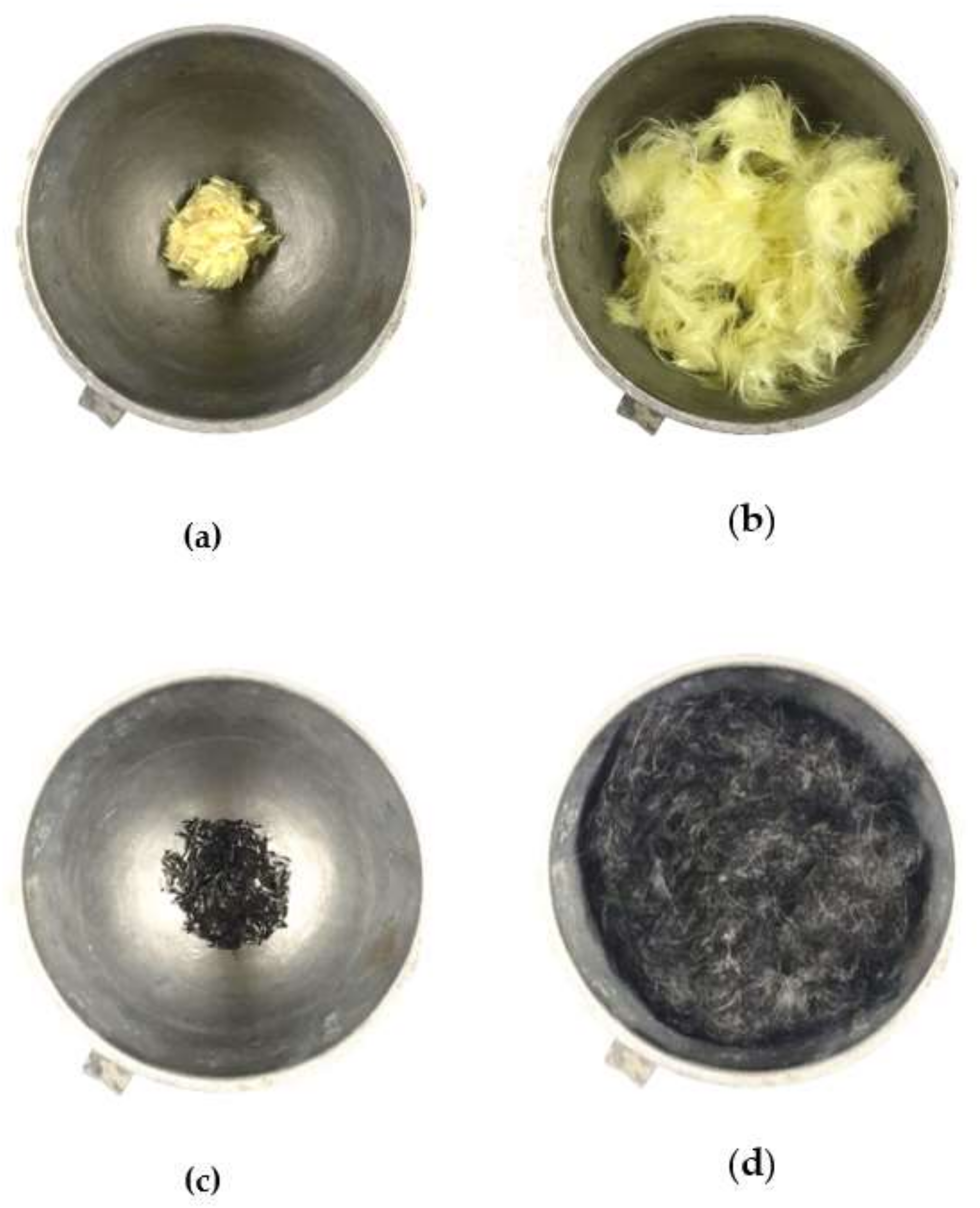
2.1.3. Kevlar Fiber
2.1.4. Carbon Fiber
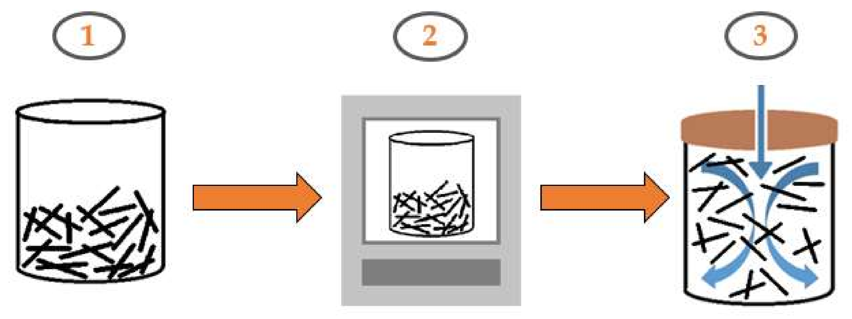
2.1.5. Hybrid Fiber-Reinforced Concrete (HFRC)
2.2. Experimental Methods
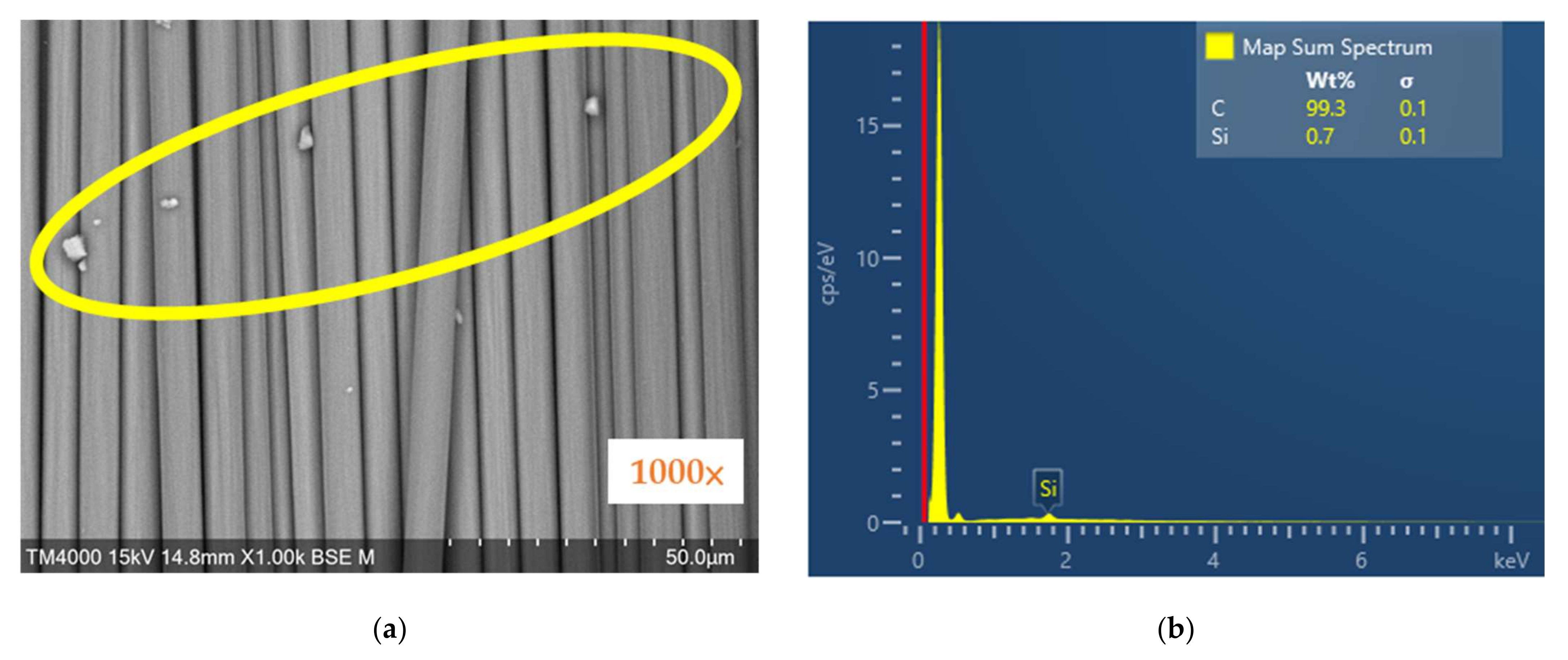
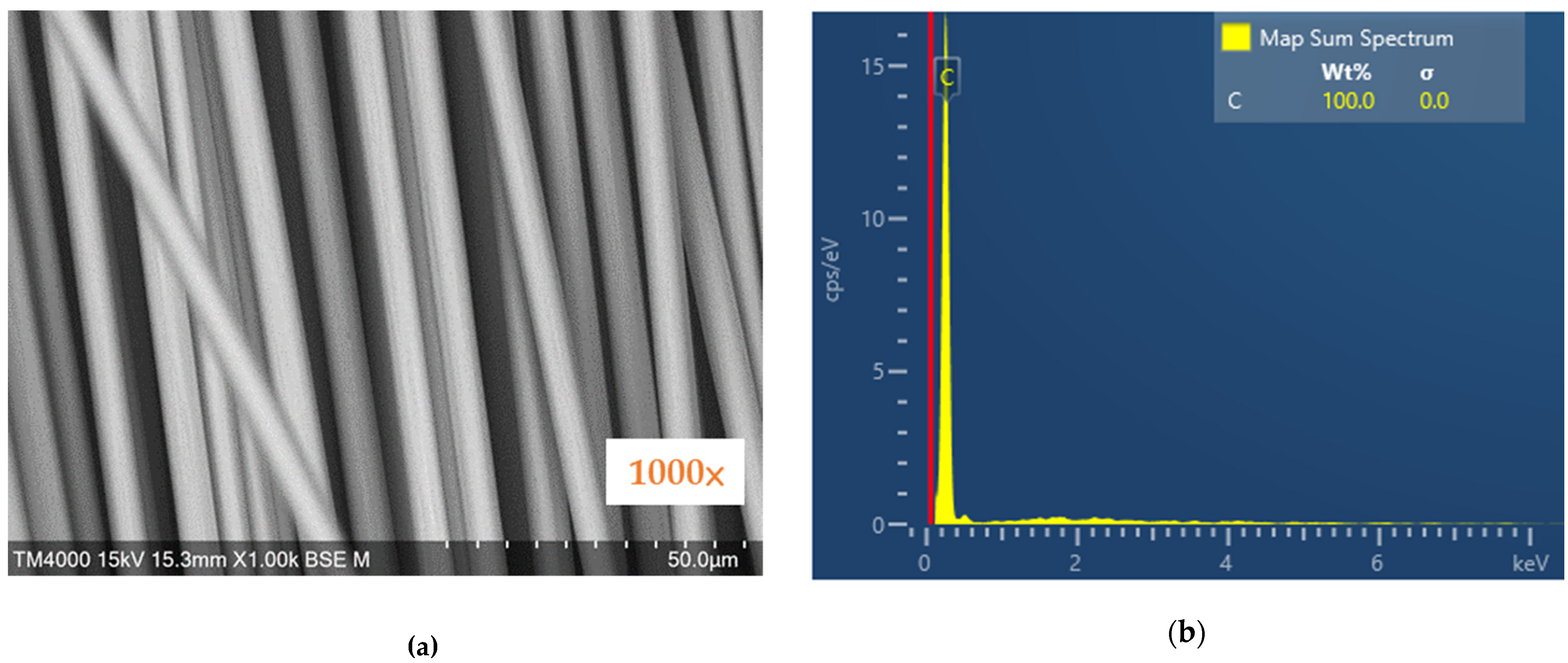
2.2.1. SEM and EDX
2.2.2. Slump Test
2.2.3. Compressive Test
2.2.4. Three-Point Bending Test
2.2.5. Splitting Tensile Test
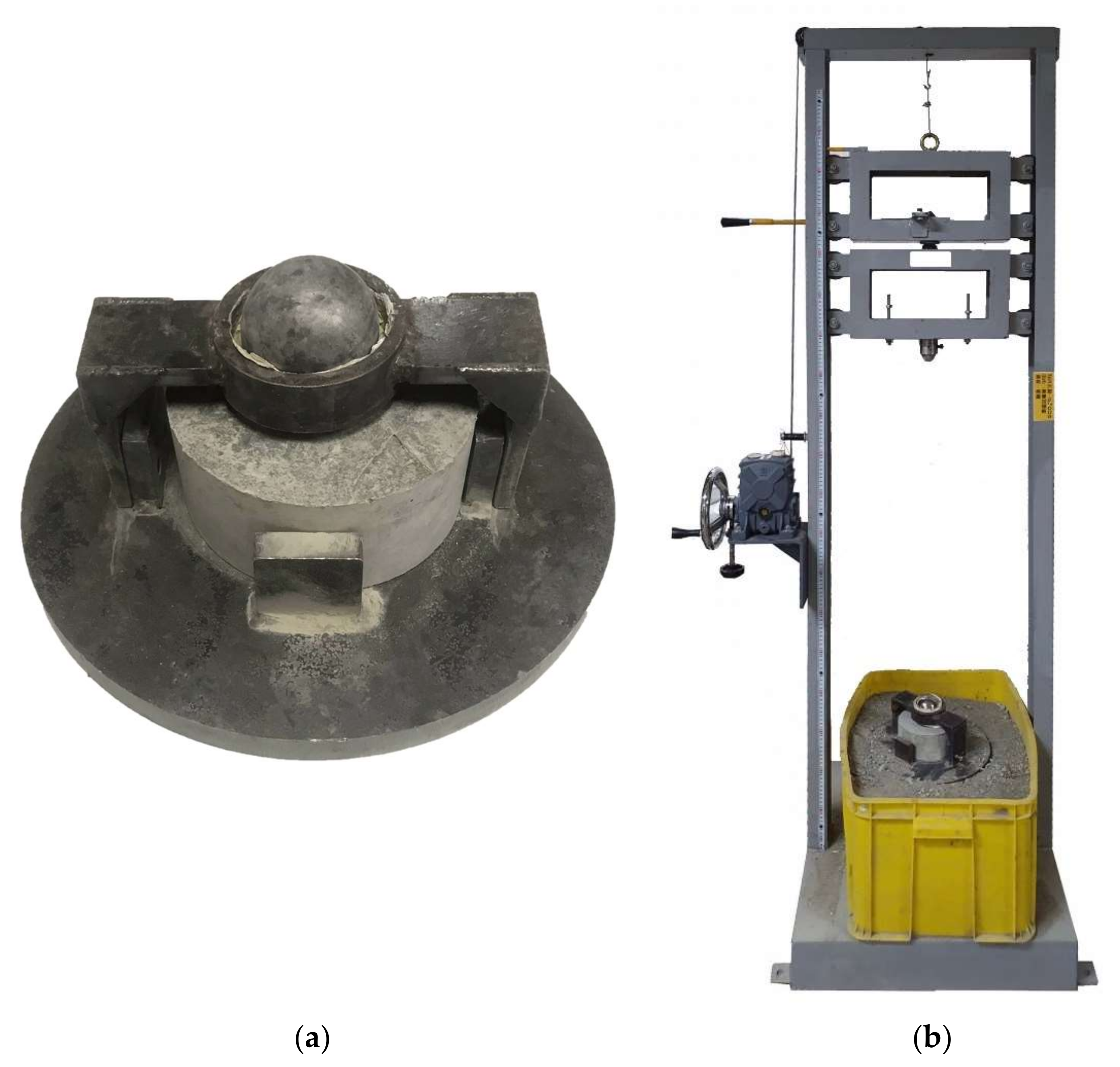
2.2.6. Impact Test
2.2.7. Optical Microscope Surface Analysis
3. Results and Discussion
3.1. SEM and EDX Graph Results
3.2. Slump Test Results
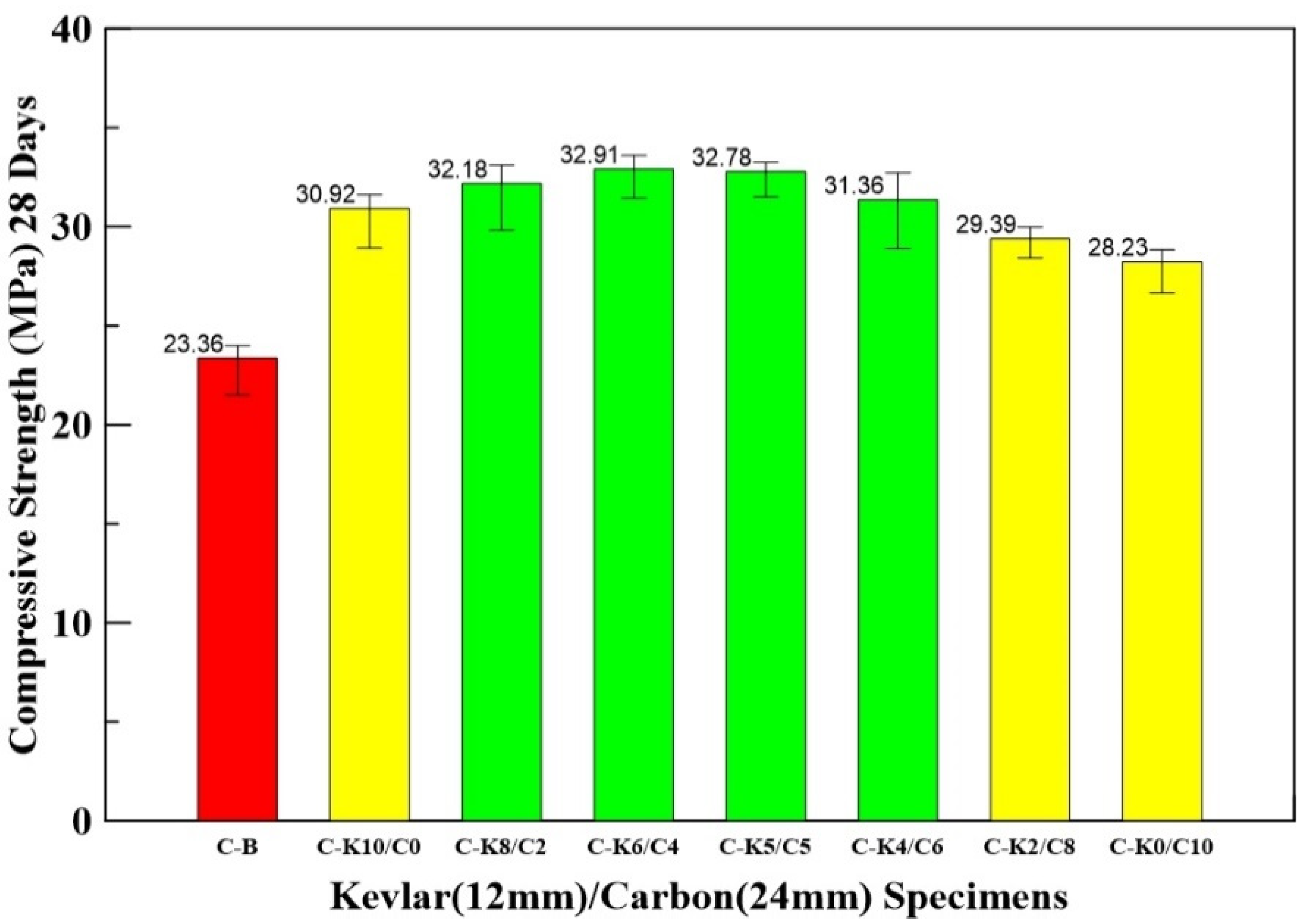
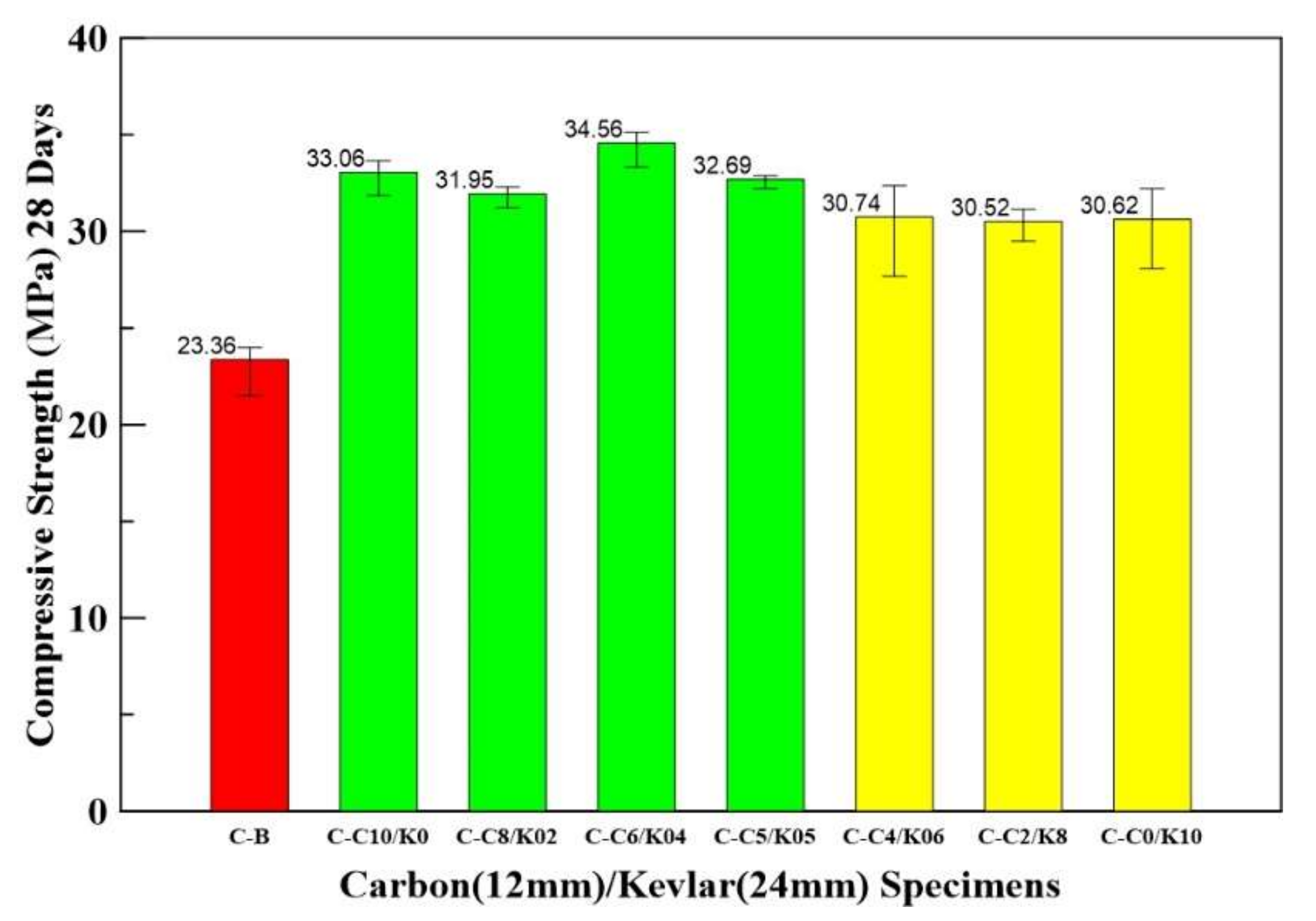
3.3. Compressive Test Results
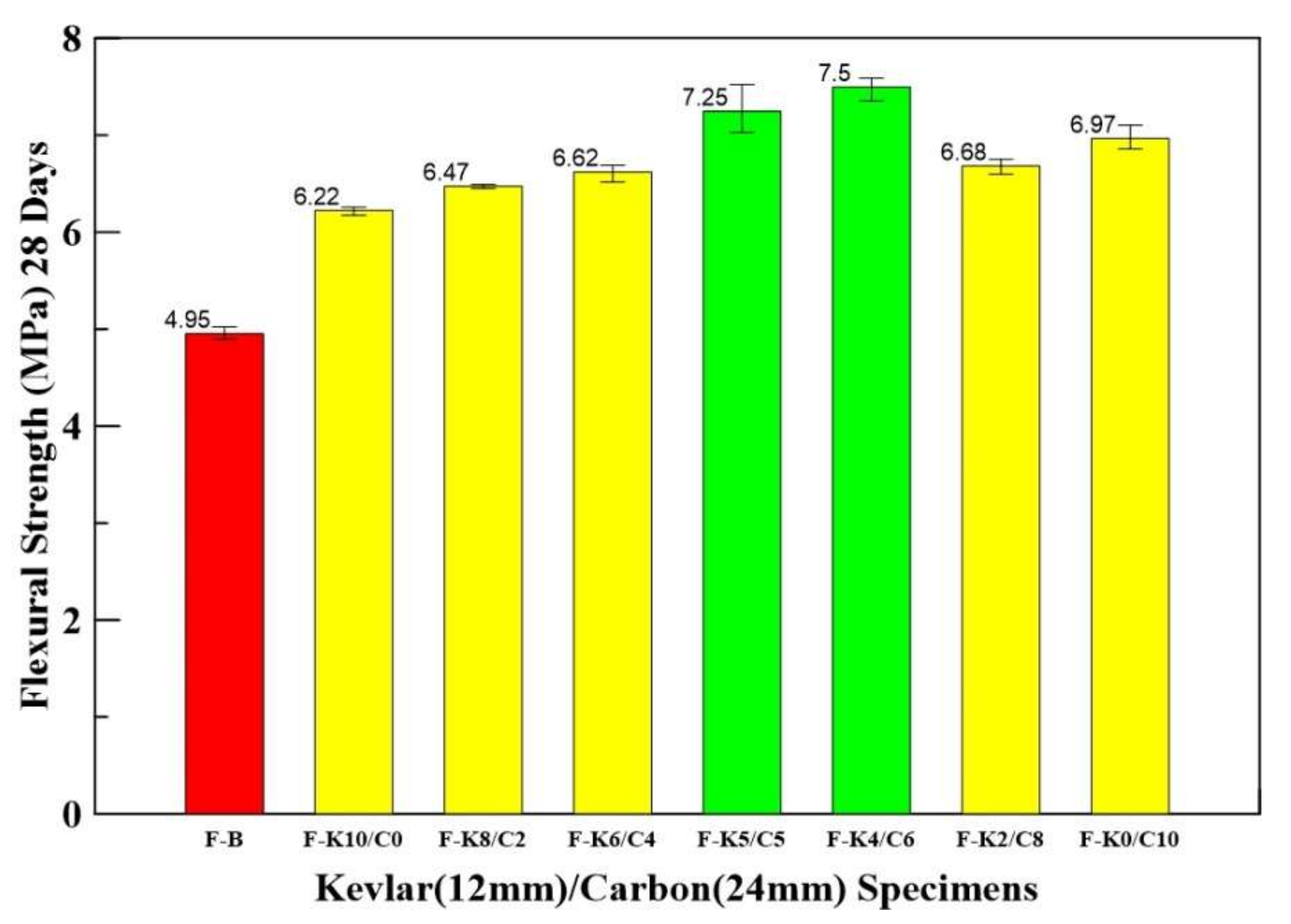
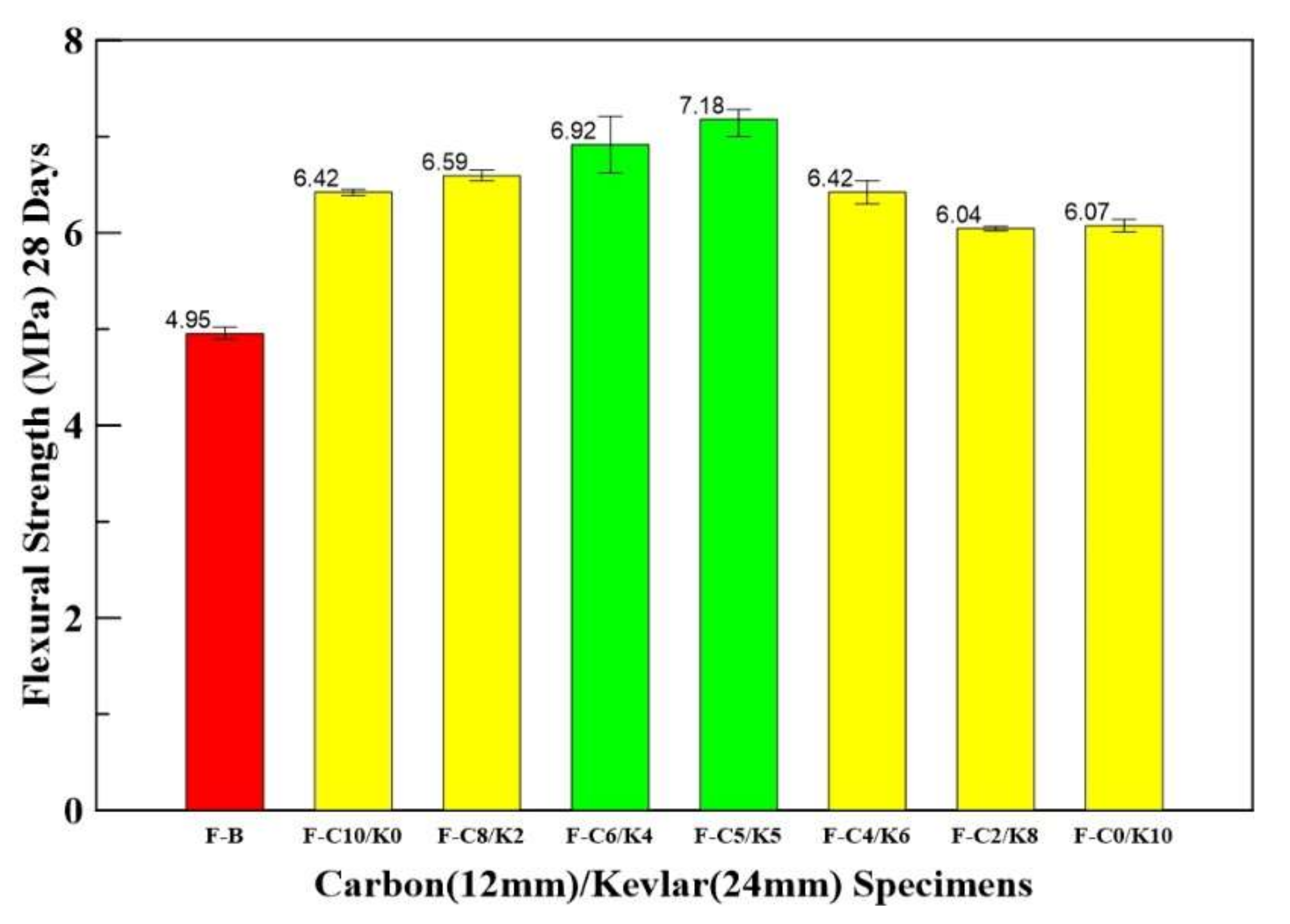
3.4. Three-Point Bending Test Results
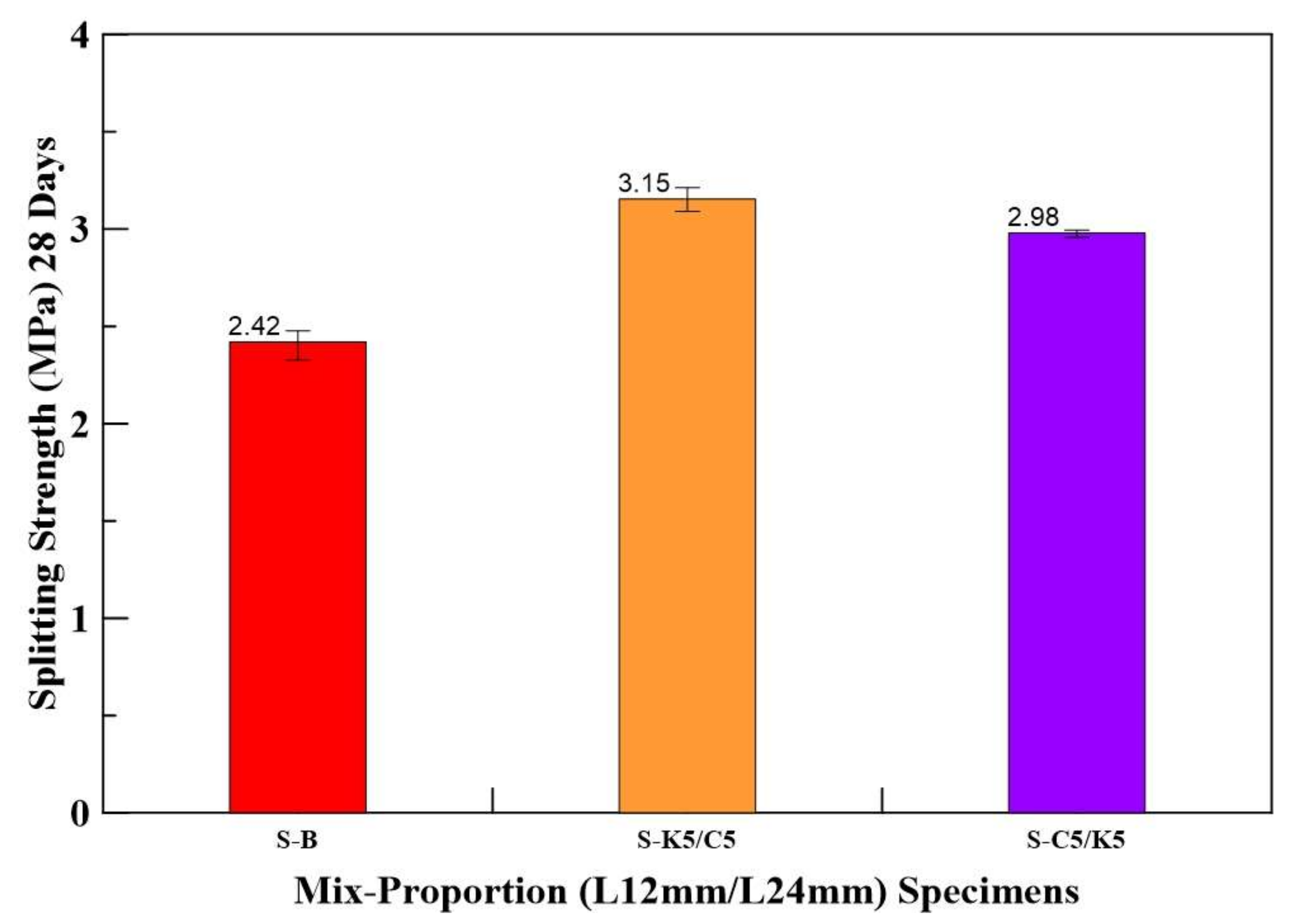
3.5. Splitting Tensile Test Results
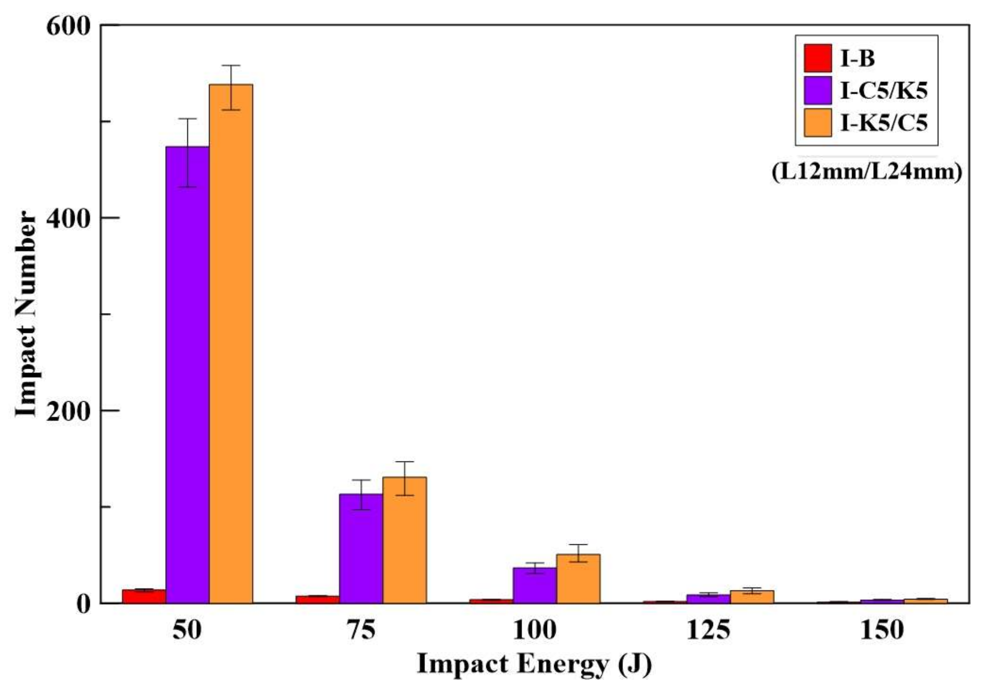
3.6. Impact Test Results
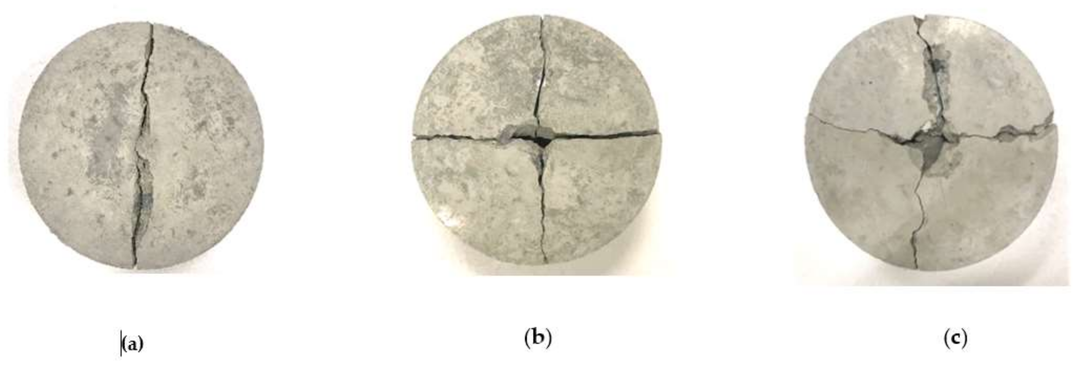
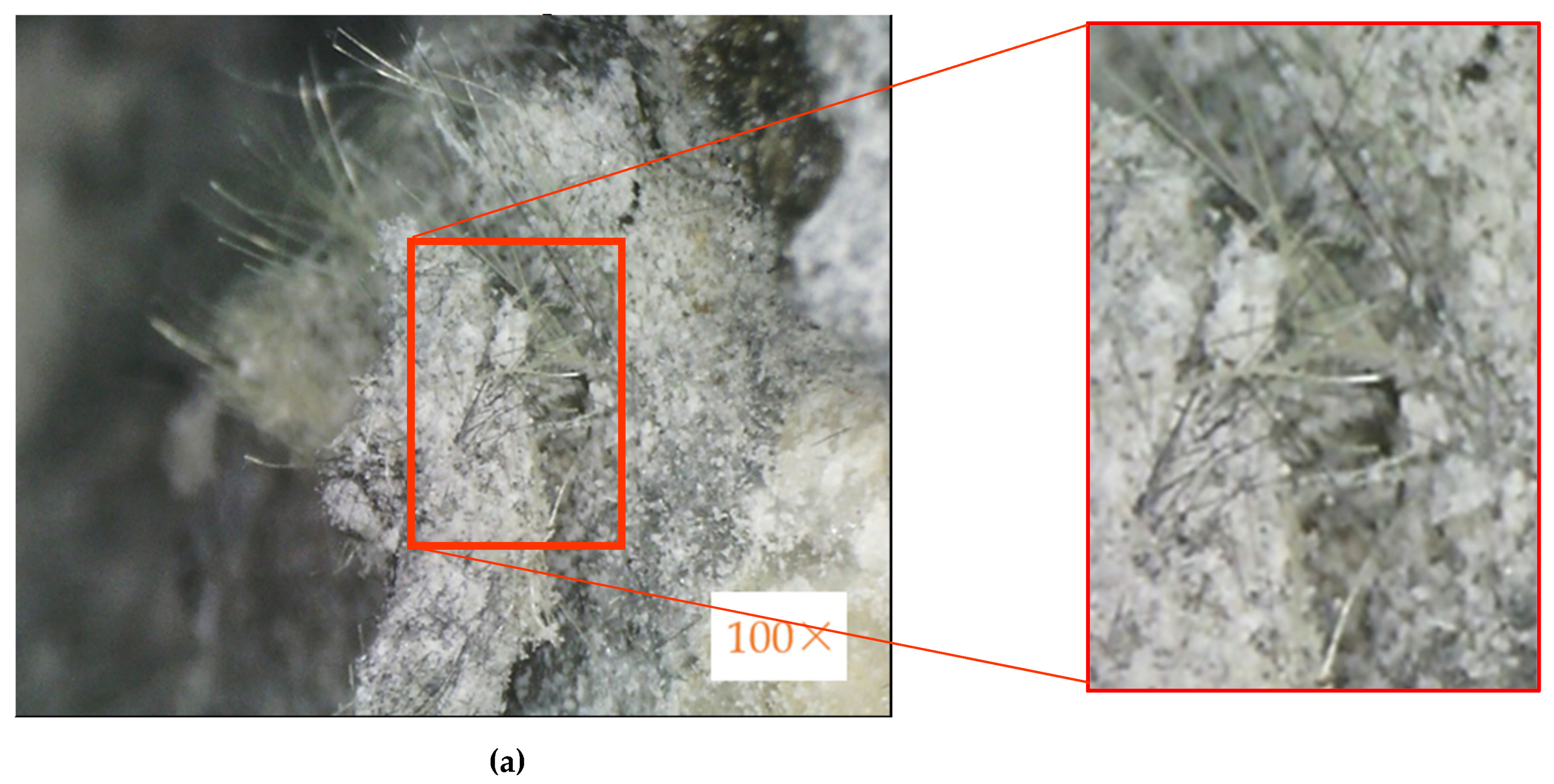
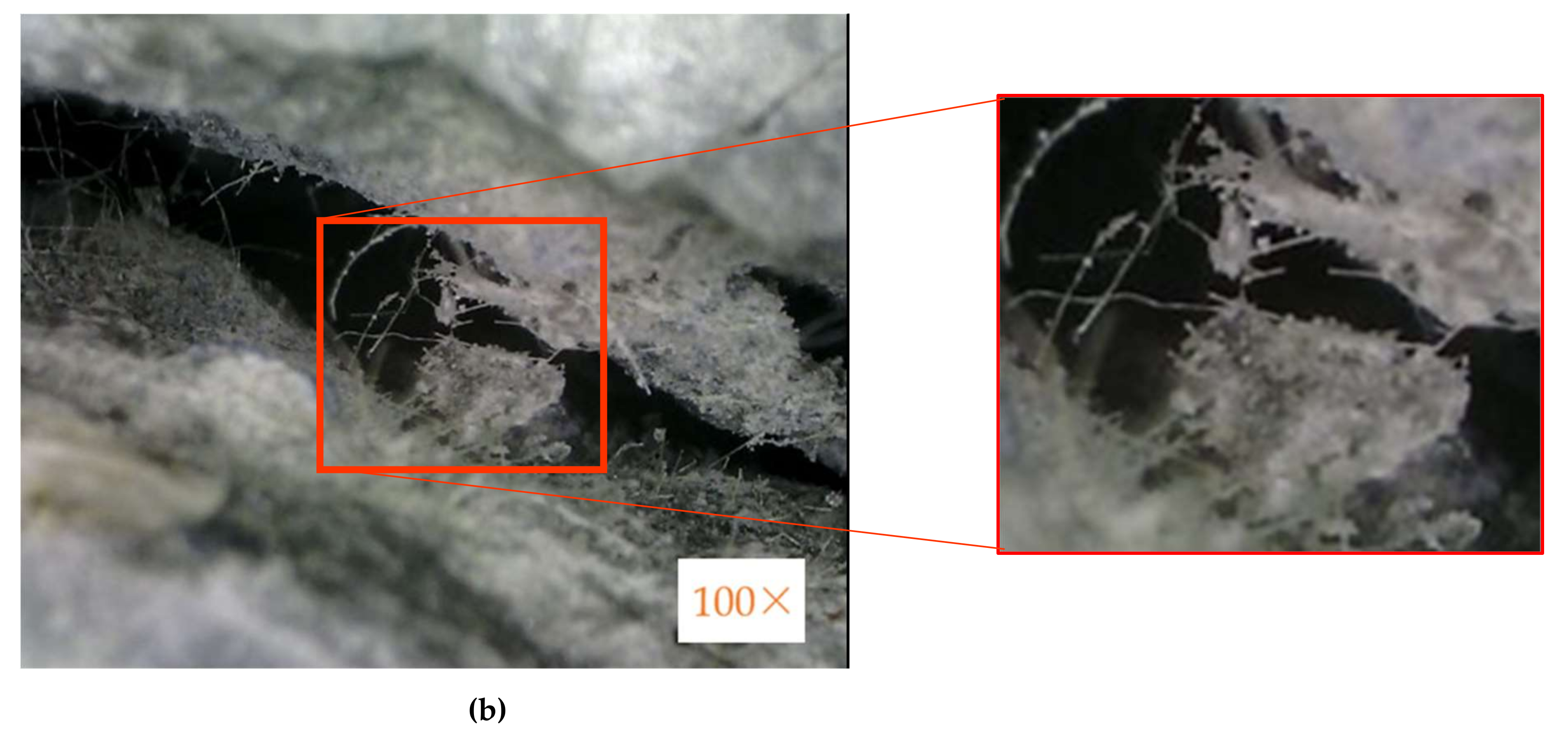
3.7. Optical Microscope
4. Conclusions
- The results show that HFRC with different mix proportions has similar slump values by 1% weight cement percentage and between 70–80 mm.
- The compressive test results show that the HFRC specimens attained higher compressive strength in C-C6/K4 (60–40%) and C-C5/K5 (50–50%) mix proportions. Compared with the benchmark specimen, the compressive strengths of the C-C6/K4 and C-C5/K5 specimens increased by 48 and 40%, respectively.
- The F-K5/C5 and F-K4/C6 specimens have better flexural strength than the benchmark specimens, increasing by 46 and 51%, respectively.
- Splitting tensile test results show that the S-K5/C5 specimen has the highest splitting tensile strength. Compared with the benchmark specimen, the S-K5/C5 specimen splitting tensile strength increased by 30%.
- The I-K5/C5 specimen has the best impact resistance in the impact test and it resists 512~558 impact numbers under 50 J.
Author Contributions
Funding
Institutional Review Board Statement
Informed Consent Statement
Data Availability Statement
Conflicts of Interest
References
- Nataraja, M.C.; Dhang, N.; Gupta, A.P. Stress–strain curves for steel-fiber reinforced concrete under compression. Cem. Concr. Compos. 1999, 21, 383–390. [Google Scholar] [CrossRef]
- Ding, Y.; Kusterle, W. Compressive stress–strain relationship of steel fibre-reinforced concrete at early age. Cem. Concr. Res. 2000, 30, 1573–1579. [Google Scholar] [CrossRef]
- Pazdera, L.; Čajka, R.; Topolář, L.; Matečková, P.; Bilek, V.; Sucharda, O. Measurement and utilization of acoustic emission for the analysis and monitoring of concrete slabs on the subsoil. Period. Polytech. Civ. Eng. 2019, 63, 608–620. [Google Scholar] [CrossRef]
- Marcalikova, Z.; Cajka, R. Determination of mechanical properties of fiber reinforced concrete for numerical modelling. Civ. Environ. Eng. 2020, 16, 86–106. [Google Scholar] [CrossRef]
- Song, P.S.; Hwang, S. Mechanical properties of high-strength steel fiber-reinforced concrete. Constr. Build. Mater. 2004, 18, 669–673. [Google Scholar] [CrossRef]
- Düzgün, O.A.; Gül, R.; Aydin, A.C. Effect of steel fibers on the mechanical properties of natural lightweight aggregate concrete. Mater. Lett. 2005, 59, 3357–3363. [Google Scholar] [CrossRef]
- Tassew, S.T.; Lubell, A.S. Mechanical properties of glass fiber reinforced ceramic concrete. Constr. Build. Mater. 2014, 51, 215–224. [Google Scholar] [CrossRef]
- Kizilkanat, A.B.; Kabay, N.; Akyüncü, V.; Chowdhury, S.; Akça, A.H. Mechanical properties and fracture behavior of basalt and glass fiber reinforced concrete: An experimental study. Constr. Build. Mater. 2015, 100, 218–224. [Google Scholar] [CrossRef]
- Kumar, D.; Rex, L.K.; Sethuraman, V.S.; Gokulnath, V.; Saravanan, B. High performance glass fiber reinforced concrete. Mater. Today Proc. 2020, 33, 784–788. [Google Scholar] [CrossRef]
- Yuan, Z.; Jia, Y. Mechanical properties and microstructure of glass fiber and polypropylene fiber reinforced concrete: An experimental study. Constr. Build. Mater. 2021, 266, 121048. [Google Scholar] [CrossRef]
- Mirza, F.A.; Soroushian, P. Effects of alkali-resistant glass fiber reinforcement on crack and temperature resistance of lightweight concrete. Cem. Concr. Compos. 2002, 24, 223–227. [Google Scholar] [CrossRef]
- Dias, D.P.; Thaumaturgo, C. Fracture toughness of geopolymeric concretes reinforced with basalt fibers. Cem. Concr. Compos. 2005, 27, 49–54. [Google Scholar] [CrossRef]
- Arslan, M.E. Effects of basalt and glass chopped fibers addition on fracture energy and mechanical properties of ordinary concrete: CMOD measurement. Constr. Build. Mater. 2016, 114, 383–391. [Google Scholar] [CrossRef]
- Branston, J.; Das, S.; Kenno, S.; Taylor, C. Mechanical behaviour of basalt fibre reinforced concrete. Constr. Build. Mater. 2016, 124, 878–886. [Google Scholar] [CrossRef]
- Ramesh, B.; Eswari, S. Mechanical behaviour of basalt fibre reinforced concrete: An experimental study. Mater. Today Proc. 2021, 43, 2317–2322. [Google Scholar] [CrossRef]
- Hossain, Z.; Abdul Awal, A.S.M. Flexural response of hybrid carbon fiber thin cement composites. Constr. Build. Mater. 2011, 25, 670–677. [Google Scholar] [CrossRef]
- De Souza Abreu, F.; Ribeiro, C.C.; da Silva Pinto, J.D.; Nsumbu, T.M.; Buono, V.T.L. Influence of adding discontinuous and dispersed carbon fiber waste on concrete performance. J. Clean. Prod. 2020, 273, 122920. [Google Scholar] [CrossRef]
- Halvaei, M.; Jamshidi, M.; Latifi, M.; Ejtemaei, M. Effects of volume fraction and length of carbon short fibers on flexural properties of carbon textile reinforced engineered cementitious composites (ECCs); an experimental and computational study. Constr. Build. Mater. 2020, 245, 118394. [Google Scholar] [CrossRef]
- Tabatabaei, Z.S.; Volz, J.S.; Keener, D.I.; Gliha, B.P. Comparative impact behavior of four long carbon fiber reinforced concretes. Mater. Des. 2014, 55, 212–223. [Google Scholar] [CrossRef]
- Rangelov, M.; Nassiri, S.; Haselbach, L.; Englund, K. Using carbon fiber composites for reinforcing pervious concrete. Constr. Build. Mater. 2016, 126, 875–885. [Google Scholar] [CrossRef]
- Meng, W.; Khayat, K.H. Mechanical properties of ultra-high-performance concrete enhanced with graphite nanoplatelets and carbon nanofibers. Compos. B Eng. 2016, 107, 113–122. [Google Scholar] [CrossRef]
- Han, B.; Zhang, L.; Zhang, C.; Wang, Y.; Yu, X.; Ou, J. Reinforcement effect and mechanism of carbon fibers to mechanical and electrically conductive properties of cement-based materials. Constr. Build. Mater. 2016, 125, 479–486. [Google Scholar] [CrossRef] [Green Version]
- Talikoti, R.; Kandekar, S.B. Strength and durability study of concrete structures using aramid-fiber-reinforced polymer. Fibers 2019, 7, 11. [Google Scholar] [CrossRef] [Green Version]
- Dhanesh, S.; Kumar, K.S.; Maruthur, P.; Rejumon, R.; Usmanasha, G.S. Experimental investigation of strength of aramid kelvar and chopped carbon reinforced concrete beam. Mater. Today Proc. 2021, 45, 1269–1273. [Google Scholar] [CrossRef]
- Palanisamy, E.; Ramasamy, M. Dependency of sisal and banana fiber on mechanical and durability properties of polypropylene hybrid fiber reinforced concrete. J. Nat. Fibers 2020, 1–12. [Google Scholar] [CrossRef]
- Wei, J.; Meyer, C. Degradation mechanisms of natural fiber in the matrix of cement composites. Cem. Concr. Res. 2015, 73, 1–16. [Google Scholar] [CrossRef]
- Ganta, J.K.; Seshagiri Rao, M.V.; Mousavi, S.S.; Srinivasa Reddy, V.; Bhojaraju, C. Hybrid steel/glass fiber-reinforced self-consolidating concrete considering packing factor: Mechanical and durability characteristics. Structures 2020, 28, 956–972. [Google Scholar] [CrossRef]
- Teja Prathipati, S.R.R.; Rao, C.B.K. A study on the uniaxial behavior of hybrid graded fiber reinforced concrete with glass and steel fibers. Mater. Today Proc. 2020, 32, 764–770. [Google Scholar] [CrossRef]
- Zhong, H.; Zhang, M. Experimental study on engineering properties of concrete reinforced with hybrid recycled tyre steel and polypropylene fibres. J. Clean. Prod. 2020, 259, 120914. [Google Scholar] [CrossRef]
- Naraganti, S.R.; Pannem, R.M.R.; Putta, J. Impact resistance of hybrid fibre reinforced concrete containing sisal fibres. Ain Shams Eng. J. 2019, 10, 297–305. [Google Scholar] [CrossRef]
- Qian, C.X.; Stroeven, P. Development of hybrid polypropylene-steel fibre-reinforced concrete. Cem. Concr. Res. 2000, 30, 63–69. [Google Scholar] [CrossRef]
- Balcikanli Bankir, M.; Sevim, U.K. Performance optimization of hybrid fiber concrete according to mechanical properties. Constr. Build. Mater. 2020, 261, 119952. [Google Scholar] [CrossRef]
- Chaturvedi, R.; Singh, P.K.; Sharma, V.K. Analysis and the impact of polypropylene fiber and steel on reinforced concrete. Mater. Today Proc. 2021, 45, 2755–2758. [Google Scholar] [CrossRef]
- Shi, F.; Pham, T.M.; Hao, H.; Hao, Y. Post-cracking behaviour of basalt and macro polypropylene hybrid fibre reinforced concrete with different compressive strengths. Constr. Build. Mater. 2020, 262, 120108. [Google Scholar] [CrossRef]
- Wang, D.; Ju, Y.; Shen, H.; Xu, L. Mechanical properties of high performance concrete reinforced with basalt fiber and polypropylene fiber. Constr. Build. Mater. 2019, 197, 464–473. [Google Scholar] [CrossRef]
- Li, Z.-X.; Li, C.-H.; Shi, Y.-D.; Zhou, X.-J. Experimental investigation on mechanical properties of Hybrid Fibre Reinforced Concrete. Constr. Build. Mater. 2017, 157, 930–942. [Google Scholar] [CrossRef]
- ACI-544.1R-96. Report on Fiber Reinforced Concrete; American Concrete Institute: Farmington Hills, MI, USA, 2002; pp. 40–42. [Google Scholar]
- Teijin, An Outstanding Para-Aramid Combining Unique Properties. Available online: https://www.teijinaramid.com/wp-content/uploads/2018/10/Product-brochure-Technora.pdf (accessed on 18 August 2021).
- Li, Y.-F.; Lee, K.-F.; Kadagathur Ramanathan, G.; Cheng, T.-W.; Huang, C.-H.; Tsai, Y.-K. Static and dynamic performances of chopped carbon-fiber-reinforced mortar and concrete incorporated with disparate lengths. Materials 2021, 14, 972. [Google Scholar] [CrossRef] [PubMed]
- Li, Y.-F.; Yang, T.-H.; Kuo, C.-Y.; Tsai, Y.-K. A Study on improving the mechanical performance of carbon-fiber-reinforced cement. Materials 2019, 12, 2715. [Google Scholar] [CrossRef] [PubMed] [Green Version]
- Li, Y.-F.; Li, J.-Y.; Kadagathur Ramanathan, G.; Chang, S.-M.; Shen, M.-Y.; Tsai, Y.-K.; Huang, C.-H. An experimental study on mechanical behaviors of carbon fiber and microwave-assisted pyrolysis recycled carbon fiber-reinforced concrete. Sustainability 2021, 13, 6829. [Google Scholar] [CrossRef]
- Kadagathur Ramanathan, G. A Study on Mechanical Behavior of Fiber-Reinforced Concrete with Different Lengths of Mix-proportion. Master’s Thesis, National Taipei University of Technology, Taipei City, Taiwan, 2021. [Google Scholar]
- ASTM C33/C33M–18. Standard Specification for Concrete Aggregates; ASTM: West Conshohocken, PA, USA, 2013. [Google Scholar]
- DuPont, Kevlar® Aramid Fiber Technical Guide. Available online: https://www.dupont.com/content/dam/dupont/amer/us/en/safety/public/documents/en/Kevlar_Technical_Guide_0319.pdf (accessed on 18 August 2021).
- ASTM C143/C143M−20. Standard Test Method for Slump of Hydraulic-Cement Concrete; ASTM: West Conshohocken, PA, USA, 2020. [Google Scholar]
- ASTM C39/C39M-01. Standard Test Method for Compressive Strength of Cylindrical Concrete Specimens; ASTM: West Conshohocken, PA, USA, 2001. [Google Scholar]
- ASTM C293/C293M-16. Standard Test Method for Flexural Strength of Concrete; ASTM: West Conshohocken, PA, USA, 2016. [Google Scholar]
- ASTM C496/C496M–17. Standard Test Method for Splitting Tensile Strength of Cylindrical Concrete Specimens; ASTM: West Conshohocken, PA, USA, 2017. [Google Scholar]
- ACI 544.2R-89. Measurement of Properties of Fiber Reinforced Concrete; American Concrete Institute: Farmington Hills, MI, USA, 1999; pp. 6–7. [Google Scholar]


| Material Property | Fiber | |
|---|---|---|
| Kevlar® 29 | Carbon | |
| Density (g/cm3) | 1.44 | 1.81 |
| Tensile Strength (MPa) | 2920 | 4900 |
| Elastic Modulus (GPa) | 70.5 | 250 |
| Elongation at Break (%) | 3.6 | 2.0 |
| Experiment | Fiber Mix-Proportion | HFRC (Kevlar 12 mm/ Carbon 24 mm) | HFRC (Carbon 12 mm/ Kevlar 24 mm) | Benchmark | Total |
|---|---|---|---|---|---|
| Compressive Test | 100–0% | 3 | 3 | 3 | 45 |
| 80–20% | 3 | 3 | |||
| 60–40% | 3 | 3 | |||
| 50–50% | 3 | 3 | |||
| 40–60% | 3 | 3 | |||
| 20–80% | 3 | 3 | |||
| 0–100% | 3 | 3 | |||
| Flexural Test | 100–0% | 3 | 3 | 3 | 45 |
| 80–20% | 3 | 3 | |||
| 60–40% | 3 | 3 | |||
| 50–50% | 3 | 3 | |||
| 40–60% | 3 | 3 | |||
| 20–80% | 3 | 3 | |||
| 0–100% | 3 | 3 | |||
| Splitting Tensile Test | 50–50% | 3 | 3 | 3 | 9 |
| Impact Test | 50–50% | 20 | 20 | 20 | 60 |
| Addition of Chopped Fiber | 0 | 1% Kevlar ® 29 Fiber | 1% Carbon Fiber |
|---|---|---|---|
| Slump (mm) | 230 | 70 | 80 |
| Specimen | Benchmark | Kevlar/Carbon HFRC Specimen (L12 mm/L24 mm) | ||||||
|---|---|---|---|---|---|---|---|---|
| C-B | C-K10/C0 | C-K8/C2 | C-K6/C4 | C-K5/C5 | C-K4/C6 | C-K2/C8 | C-K0/C10 | |
| Compressive Strength (MPa) | 22.13 | 29.60 | 30.77 | 32.13 | 31.97 | 30.25 | 29.01 | 27.26 |
| 23.97 | 31.54 | 32.64 | 33.01 | 33.14 | 31.11 | 29.19 | 28.60 | |
| 23.98 | 31.61 | 33.11 | 33.60 | 33.24 | 32.72 | 29.98 | 28.83 | |
| Average Compressive Strength (MPa) | 23.36 | 30.92 | 32.18 | 32.91 | 32.78 | 31.36 | 29.39 | 28.23 |
| Increase (%) | - | 32 | 28 | 41 | 40 | 34 | 26 | 21 |
| Specimen | Benchmark | Carbon/Kevlar HFRC Specimen (L12 mm/L24 mm) | ||||||
|---|---|---|---|---|---|---|---|---|
| C-B | C-C10/K0 | C-C8/K2 | C-C6/K4 | C-C5/K5 | C-C4/K6 | C-C2/K8 | C-C0/K10 | |
| Compressive Strength (MPa) | 22.13 | 32.44 | 31.59 | 33.90 | 32.39 | 29.31 | 30.10 | 29.68 |
| 23.97 | 33.07 | 31.95 | 34.65 | 32.80 | 30.55 | 30.33 | 29.98 | |
| 23.98 | 33.65 | 32.31 | 35.13 | 32.88 | 32.36 | 31.12 | 32.21 | |
| Average Compressive Strength (MPa) | 23.36 | 33.06 | 31.95 | 34.56 | 32.69 | 30.74 | 30.52 | 30.62 |
| Increase (%) | - | 41 | 37 | 48 | 40 | 32 | 31 | 31 |
| Specimen | Benchmark | Kevlar/Carbon HFRC Specimen (L12 mm/L24 mm) | ||||||
|---|---|---|---|---|---|---|---|---|
| F-B | F-K10/C0 | F-K8/C2 | F-K6/C4 | F-K5/C5 | F-K4/C6 | F-K2/C8 | F-K0/C10 | |
| Flexural Strength (MPa) | 4.90 | 6.17 | 6.45 | 6.52 | 7.03 | 7.35 | 6.60 | 6.60 |
| 4.94 | 6.24 | 6.48 | 6.66 | 7.18 | 7.55 | 6.70 | 6.70 | |
| 5.02 | 6.26 | 6.49 | 6.69 | 7.52 | 7.59 | 6.75 | 6.75 | |
| Average Flexural Strength (MPa) | 4.92 | 6.22 | 6.47 | 6.62 | 7.25 | 7.50 | 6.68 | 6.97 |
| Increase (%) | - | 26 | 31 | 34 | 46 | 51 | 35 | 41 |
| Specimen | Benchmark | Kevlar/Carbon HFRC Specimen (L12 mm/L24 mm) | ||||||
|---|---|---|---|---|---|---|---|---|
| F-B | F-K10/C0 | F-K8/C2 | F-K6/C4 | F-K5/C5 | F-K4/C6 | F-K2/C8 | F-K0/C10 | |
| Flexural Strength (MPa) | 4.90 | 6.39 | 6.54 | 6.62 | 7.00 | 6.30 | 6.02 | 6.01 |
| 4.94 | 6.43 | 6.58 | 6.92 | 7.25 | 6.43 | 6.05 | 6.07 | |
| 5.02 | 6.45 | 6.65 | 7.21 | 7.28 | 6.54 | 6.07 | 6.14 | |
| Average Flexural Strength (MPa) | 4.92 | 6.42 | 6.59 | 6.92 | 7.18 | 6.42 | 6.05 | 6.07 |
| Increase (%) | - | 30 | 33 | 40 | 45 | 30 | 22 | 23 |
| Specimen | Benchmark | HFRC Specimen (L12 mm/L24 mm) | |
|---|---|---|---|
| S-B | S-K5/C5 | S-C5/K5 | |
| Splitting Tensile Strength (MPa) | 2.33 | 3.09 | 2.96 |
| 2.46 | 3.16 | 2.99 | |
| 2.48 | 3.21 | 2.99 | |
| Average Splitting Tensile Strength (MPa) | 2.42 | 3.15 | 2.98 |
| Increase (%) | - | 30 | 23 |
| Specimen | Impact Energy (J) | Impact Number | Average Impact Number | Increase (%) | |||
|---|---|---|---|---|---|---|---|
| I-B | 150 | 1 | 1 | 1 | 2 | 1.25 | - |
| 125 | 2 | 2 | 2 | 2 | 2 | - | |
| 100 | 3 | 4 | 4 | 4 | 3.75 | - | |
| 75 | 7 | 7 | 8 | 8 | 7.5 | - | |
| 50 | 12 | 14 | 14 | 15 | 13.75 | - | |
| I-K5/C5 (L12 mm/L24 mm) | 150 | 4 | 4 | 4 | 5 | 4.25 | 244 |
| 125 | 10 | 13 | 14 | 16 | 13.25 | 565 | |
| 100 | 43 | 46 | 53 | 61 | 50.75 | 1,255 | |
| 75 | 112 | 128 | 136 | 147 | 130.75 | 1644 | |
| 50 | 512 | 532 | 551 | 558 | 538.25 | 3815 | |
| I-C5/K5 (L12 mm/L24 mm) | 150 | 3 | 3 | 4 | 4 | 2.75 | 124 |
| 125 | 7 | 8 | 9 | 11 | 8.75 | 170 | |
| 100 | 31 | 35 | 39 | 42 | 36.75 | 868 | |
| 75 | 97 | 106 | 122 | 128 | 113.25 | 1411 | |
| 50 | 432 | 477 | 483 | 503 | 473.75 | 3346 | |
Publisher’s Note: MDPI stays neutral with regard to jurisdictional claims in published maps and institutional affiliations. |
© 2021 by the authors. Licensee MDPI, Basel, Switzerland. This article is an open access article distributed under the terms and conditions of the Creative Commons Attribution (CC BY) license (https://creativecommons.org/licenses/by/4.0/).
Share and Cite
Li, Y.-F.; Wang, H.-F.; Syu, J.-Y.; Ramanathan, G.K.; Tsai, Y.-K.; Lok, M.H. Mechanical Properties of Aramid/Carbon Hybrid Fiber-Reinforced Concrete. Materials 2021, 14, 5881. https://doi.org/10.3390/ma14195881
Li Y-F, Wang H-F, Syu J-Y, Ramanathan GK, Tsai Y-K, Lok MH. Mechanical Properties of Aramid/Carbon Hybrid Fiber-Reinforced Concrete. Materials. 2021; 14(19):5881. https://doi.org/10.3390/ma14195881
Chicago/Turabian StyleLi, Yeou-Fong, Hsin-Fu Wang, Jin-Yuan Syu, Gobinathan Kadagathur Ramanathan, Ying-Kuan Tsai, and Man Hoi Lok. 2021. "Mechanical Properties of Aramid/Carbon Hybrid Fiber-Reinforced Concrete" Materials 14, no. 19: 5881. https://doi.org/10.3390/ma14195881
APA StyleLi, Y.-F., Wang, H.-F., Syu, J.-Y., Ramanathan, G. K., Tsai, Y.-K., & Lok, M. H. (2021). Mechanical Properties of Aramid/Carbon Hybrid Fiber-Reinforced Concrete. Materials, 14(19), 5881. https://doi.org/10.3390/ma14195881