
The Effect of Displacement Amplitude on Fretting Wear Behavior and Damage Mechanism of Alloy 690 in Different Gaseous Atmospheres

 ,
,
Abstract
:1. Introduction
2. Materials and Methods
3. Results
4. Discussion
5. Conclusions
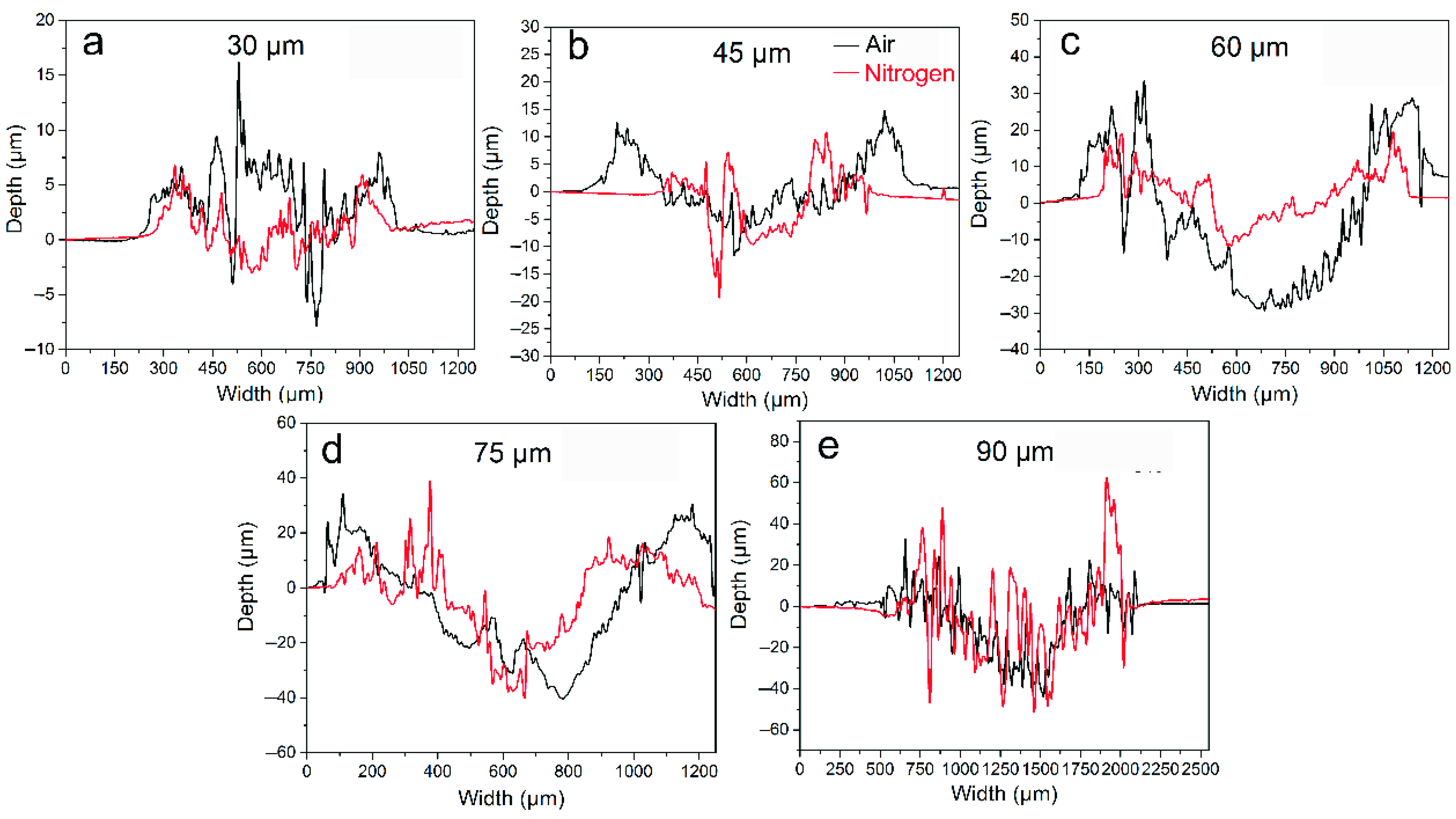
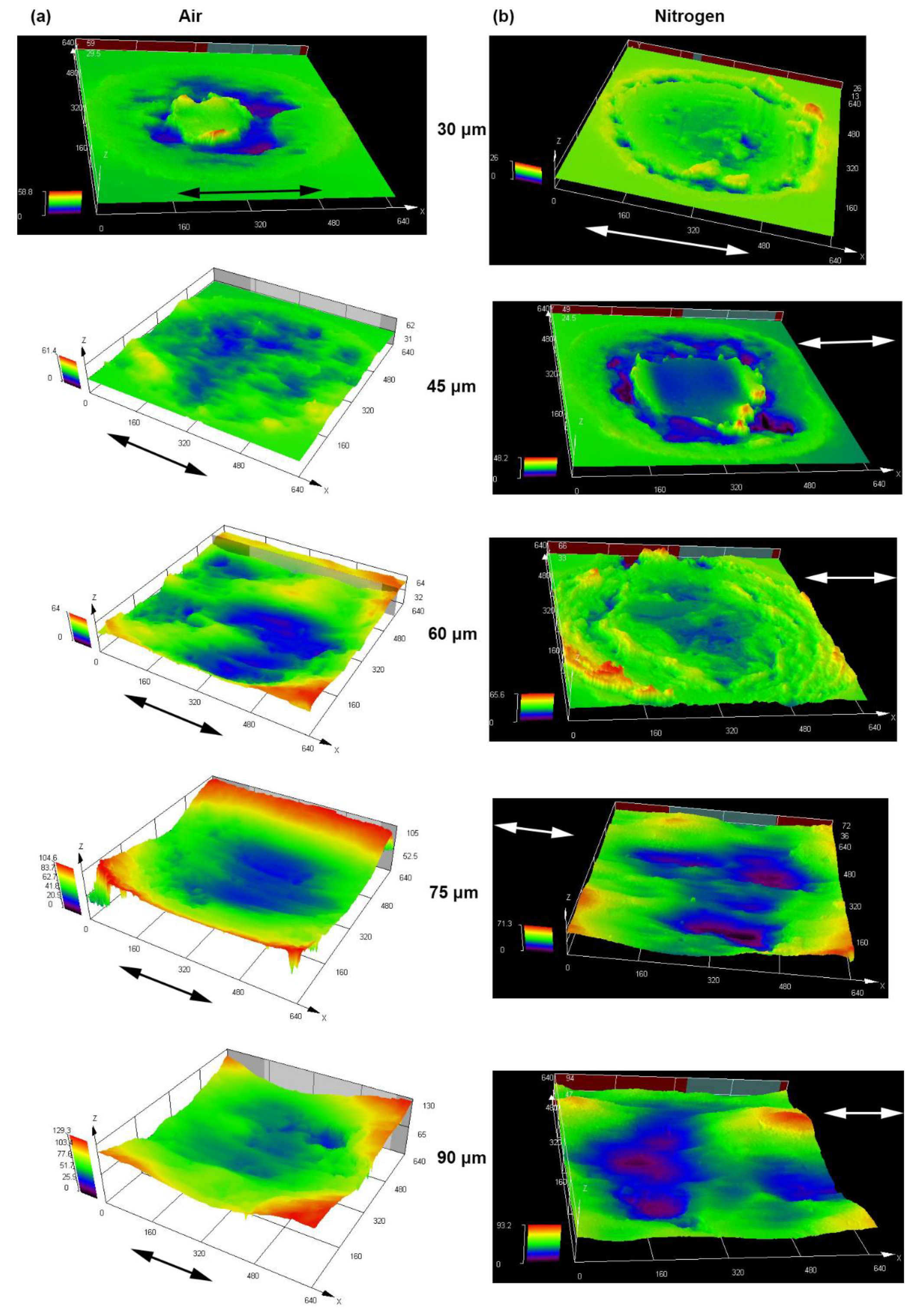
- In air, the friction coefficient gradually increased with the increase in the displacement amplitude, which conformed to the universal law. In nitrogen, however, it had the highest point at 60 μm due to very strong adhesion. Whether in air or nitrogen, the wear volume gradually increased with the increase in the displacement amplitude. The wear volume in air was larger than that in nitrogen except for the condition at 30 μm. At 30 μm, the wear volume in air was slightly smaller.
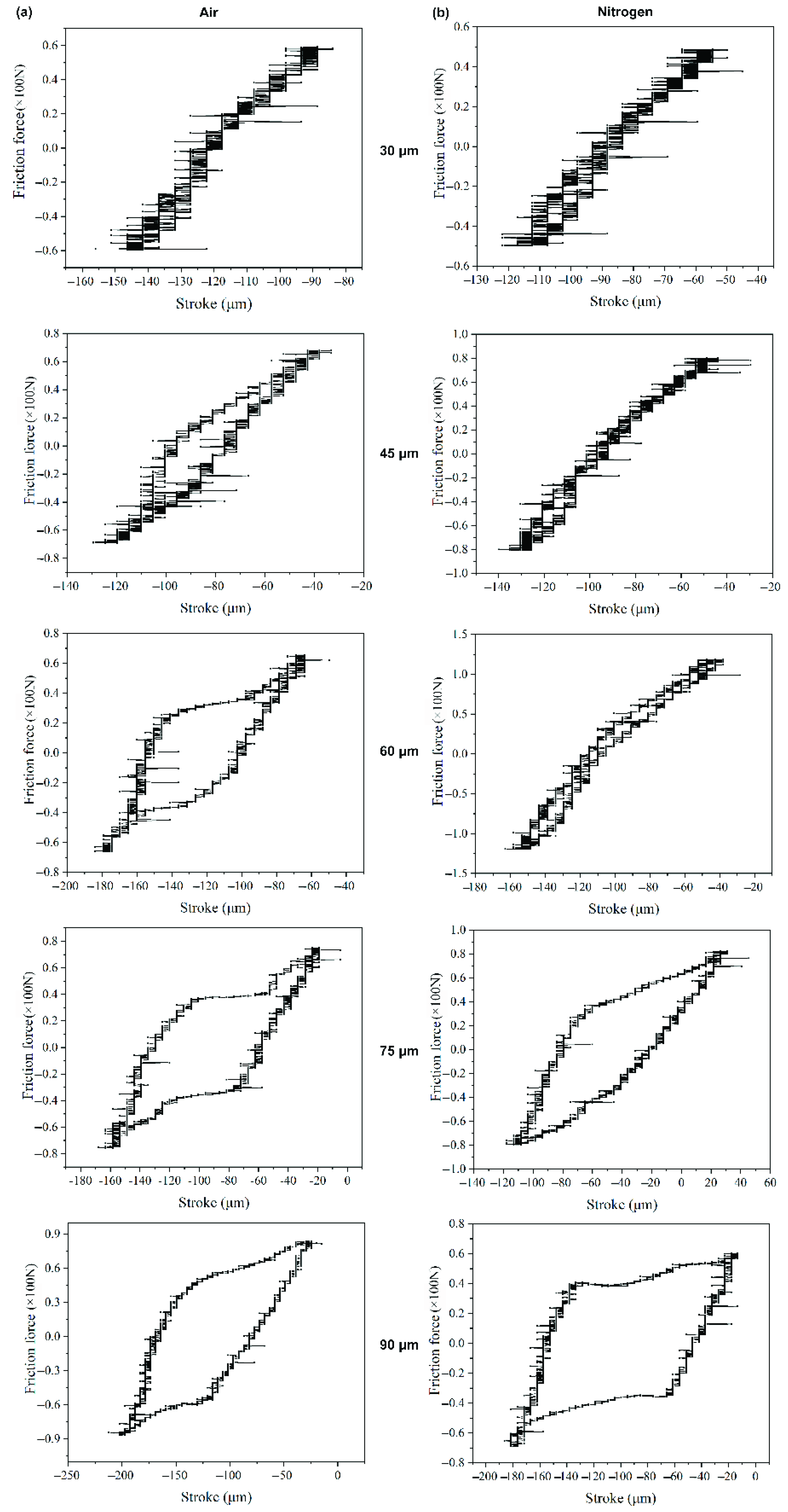
- With the increase in displacement amplitude, a transition from partial slip to mixed stick-slip to final gross slip occurred along with the change of Ft-D curves from linear to elliptic to, finally, parallelogrammical. Correspondingly, the fretting running status changed from partial slip regime to mixed regime to gross slip regime. With the increase in the displacement amplitude, the transition from partial slip to gross slip in nitrogen was delayed as compared with air due to the strong adhesion actuated by low oxygen content in a reducing environment.
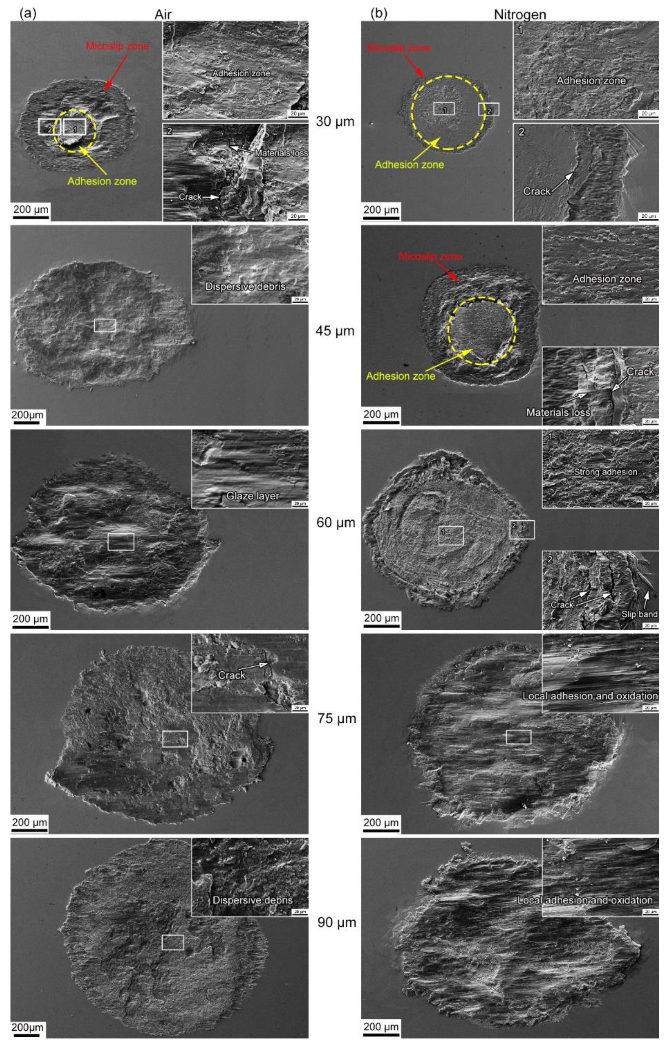
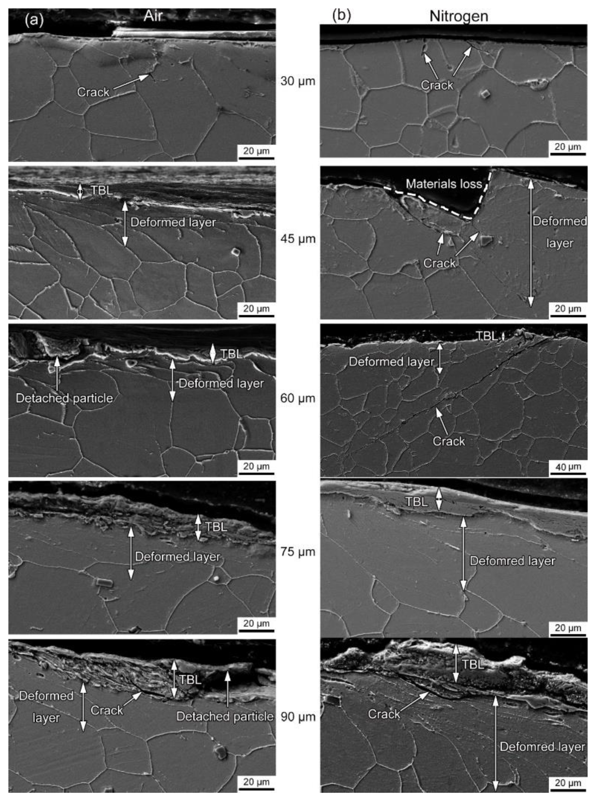
- Whether in air or nitrogen, the competitive relation between fretting-induced fatigue and fretting-induced wear was prominent. The cracking velocity was more rapid than wear, and fretting-induced fatigue dominated at 30 μm in air but at 30–60 μm in nitrogen. Fretting-induced wear won the competition at 45–90 μm in air but at 75–90 μm in nitrogen.
Author Contributions
Funding
Institutional Review Board Statement
Informed Consent Statement
Data Availability Statement
Conflicts of Interest
References
- Yue, T.; Wahab, M.A. Finite element analysis of fretting wear under variable coefficient of friction and different contact regimes. Tribol. Int. 2017, 107, 274–282. [Google Scholar] [CrossRef]
- Done, V.; Kesavan, D.; Krishna, R.M.; Chaise, T.; Nelias, D. Semi analytical fretting wear simulation including wear debris. Tribol. Int. 2017, 109, 1–9. [Google Scholar] [CrossRef]
- Hu, Z.; Lu, W.; Thouless, M.; Barber, J. Effect of plastic deformation on the evolution of wear and local stress fields in fretting. Int. J. Solids Struct. 2016, 82, 1–8. [Google Scholar] [CrossRef]
- Jin, O.; Mall, S. Effects of slip on fretting behavior: Experiments and analyses. Wear 2004, 256, 671–684. [Google Scholar] [CrossRef]
- Vingsbo, O.; Söderberg, S. On fretting maps. Wear 1988, 126, 131–147. [Google Scholar] [CrossRef]
- Lee, C.Y.; Tian, L.S.; Bae, J.W.; Chai, Y.S. Application of influence function method on the fretting wear of tube-to-plate contact. Tribol. Int. 2009, 42, 951–957. [Google Scholar] [CrossRef]
- Leonard, B.D.; Sadeghi, F.; Shinde, S.; Mittelbach, M. A Numerical and Experimental Investigation of Fretting Wear and a New Procedure for Fretting Wear Maps. Tribol. Trans. 2012, 55, 313–324. [Google Scholar] [CrossRef]
- Ghosh, A.; Wang, W.; Sadeghi, F. An elastic–plastic investigation of third body effects on fretting contact in partial slip. Int. J. Solids Struct. 2016, 81, 95–109. [Google Scholar] [CrossRef]
- Pearson, S.; Shipway, P. Is the wear coefficient dependent upon slip amplitude in fretting? Vingsbo and Söderberg revisited. Wear 2015, 330–331, 93–102. [Google Scholar] [CrossRef]
- Zhou, Z.R.; Vincent, L. Mixed fretting regime. Wear 1995, 181–183 Pt 2, 531–536. [Google Scholar] [CrossRef]
- Wang, Z.; Lu, Y.; Li, J.; Shoji, T. Effect of pH value on the fretting wear behavior of Inconel 690 alloy. Tribol. Int. 2015, 95, 162–169. [Google Scholar] [CrossRef]
- Li, J.; Yang, B.; Lu, Y.; Xin, L.; Wang, Z.; Shoji, T. The effect of normal force on fretting corrosion behavior of Inconel 690 in 3.5% sodium chloride. Mater. Charact. 2017, 131, 224–233. [Google Scholar] [CrossRef]
- Xin, L.; Yang, B.; Wang, Z.; Li, J.; Lu, Y.; Shoji, T. Effect of normal force on fretting wear behavior and mechanism of Alloy 690TT in high temperature water. Wear 2016, 368–369, 210–218. [Google Scholar] [CrossRef]
- Guo, X.; Lai, P.; Tang, L.; Wang, J.; Zhang, L. Effects of sliding amplitude and normal load on the fretting wear behavior of alloy 690 tube exposed to high temperature water. Tribol. Int. 2017, 116, 155–163. [Google Scholar] [CrossRef]
- Li, J.; Lu, Y. Effects of displacement amplitude on fretting wear behaviors and mechanism of Inconel 600 alloy. Wear 2013, 304, 223–230. [Google Scholar] [CrossRef]
- Yun, J.Y.; Park, M.C.; Shin, G.S.; Heo, J.H.; Kim, D.I.; Kim, S.J. Effects of amplitude and frequency on the wear mode change of Inconel 690 SG tube mated with SUS 409. Wear 2014, 313, 83–88. [Google Scholar] [CrossRef]
- Xin, L.; Wang, Z.H.; Li, J.; Lu, Y.H.; Shoji, T. Fretting Wear Behavior and Mechanism of Inconel 690 Alloy Related to the Displacement Amplitude. Tribol. Trans. 2016, 60, 913–922. [Google Scholar] [CrossRef]
- Li, J.; Ma, M.; Lu, Y.; Xin, L. Evolution of wear damage in Inconel 600 alloy due to fretting against type 304 stainless steel. Wear 2015, 346–347, 15–21. [Google Scholar] [CrossRef]
- Xin, L.; Han, Y.; Ling, L.; Zhang, W.; Lu, Y.; Shoji, T. The Evolution of Fretting Wear Behavior and Damage Mechanism in Alloy 690TT with Cycle Number. Materials 2020, 13, 2417. [Google Scholar] [CrossRef] [PubMed]
- Xin, L.; Lu, Y.; Shoji, T. The comparative study on nanostructured tribolayers of Alloy 690TT subjected to fretting wear under different oxygen contents. Mater. Charact. 2017, 131, 157–167. [Google Scholar] [CrossRef]
- Xin, L.; Huang, Q.; Han, Y.; Lu, Y.; Zhang, W.; Shoji, T. The damage mechanism of Alloy 690TT against Alloy 600 caused by fretting wear in room temperature pure water. Mater. Charact. 2020, 161, 110176. [Google Scholar] [CrossRef]
- Yun, J.Y.; Shin, G.S.; Kim, D.I.; Lee, H.S.; Kang, W.S.; Kim, S.J. Effect of carbide size and spacing on the fretting wear behavior of Inconel 690 SG tube mated with SUS 409. Wear 2015, 338–339, 252–257. [Google Scholar] [CrossRef]
- Hong, J.-K.; Kim, I.-S.; Park, C.-Y.; Kim, E.-S. Microstructural effects on the fretting wear of Inconel 690 steam generator tube. Wear 2005, 259, 349–355. [Google Scholar] [CrossRef]
- Lee, Y.-H.; Kim, H.-K.; Kim, H.-D.; Park, C.-Y.; Kim, I.-S. A comparative study on the fretting wear of steam generator tubes in korean power plants. Wear 2003, 255, 1198–1208. [Google Scholar] [CrossRef]
- Lee, Y.-H.; Kim, I.-S. The effect of subsurface deformation on the wear behavior of steam generator tube materials. Wear 2002, 253, 438–447. [Google Scholar] [CrossRef]
- Xin, L.; Yang, B.; Li, J.; Lu, Y.; Shoji, T. Microstructural characteristics of Alloy 690TT subjected to fretting corrosion in high temperature water. Corros. Sci. 2017, 123, 116–128. [Google Scholar] [CrossRef]
- Jeong, S.-H.; Cho, C.-W.; Lee, Y.-Z. Friction and wear of Inconel 690 for steam generator tube in elevated temperature water under fretting condition. Tribol. Int. 2005, 38, 283–288. [Google Scholar] [CrossRef]
- Zhang, X.-Y.; Ren, P.-D.; Peng, J.-F.; Zhu, M.-H. Fretting wear behavior of Inconel 690 in hydrazine environments. Trans. Nonferrous Met. Soc. China 2014, 24, 360–367. [Google Scholar] [CrossRef]
- Mi, X.; Cai, Z.; Xiong, X.; Qian, H.; Tang, L.; Xie, Y.; Peng, J.; Zhu, M.-H. Investigation on fretting wear behavior of 690 alloy in water under various temperatures. Tribol. Int. 2016, 100, 400–409. [Google Scholar] [CrossRef] [Green Version]
- Lim, M.-K.; Oh, S.-D.; Lee, Y.-Z. Friction and wear of Inconel 690 and Inconel 600 for steam generator tube in room temperature water. Nucl. Eng. Des. 2003, 226, 97–105. [Google Scholar] [CrossRef]
- Xin, L.; Han, Y.; Ling, L.; Lu, Y.; Shoji, T. Effects of dissolved oxygen on partial slip fretting corrosion of Alloy 690TT in high temperature pure water. J. Nucl. Mater. 2020, 542, 152483. [Google Scholar] [CrossRef]
- Mi, X.; Wang, W.; Xiong, X.; Qian, H.; Tang, L.; Xie, Y.; Peng, J.; Cai, Z.; Zhu, M.-H. Investigation of fretting wear behavior of Inconel 690 alloy in tube/plate contact configuration. Wear 2015, 328–329, 582–590. [Google Scholar] [CrossRef]
- Xin, L.; Han, Y.; Lu, Y.; Zhang, W.; Shoji, T. The Damage Mechanism of Alloy 690TT Caused by Fretting Wear in a Flowing Nitrogen Environment. Tribol. Trans. 2021, 64, 111–118. [Google Scholar] [CrossRef]
- Zhou, Z.R.; Nakazawa, K.; Zhu, M.H.; Maruyama, N.; Kapsa, P.; Vincent, L. Progress in fretting maps. Tribol. Int. 2006, 39, 1068–1073. [Google Scholar] [CrossRef]
- Zhu, M.; Zhou, Z. On the mechanisms of various fretting wear modes. Tribol. Int. 2011, 44, 1378–1388. [Google Scholar] [CrossRef]
- Velkavrh, I.; Ausserer, F.; Klien, S.; Voyer, J.; Ristow, A.; Brenner, J.; Forêt, P.; Diem, A. The influence of temperature on friction and wear of unlubricated steel/steel contacts in different gaseous atmospheres. Tribol. Int. 2016, 98, 155–171. [Google Scholar] [CrossRef]
- Esteves, M.; Ramalho, A.; Ramos, F. Fretting behavior of the AISI 304 stainless steel under different atmosphere environments. Tribol. Int. 2015, 88, 56–65. [Google Scholar] [CrossRef]
- Velkavrh, I.; Ausserer, F.; Klien, S.; Brenner, J.; Forêt, P.; Diem, A. The effect of gaseous atmospheres on friction and wear of steel–steel contacts. Tribol. Int. 2014, 79, 99–110. [Google Scholar] [CrossRef]
- Cai, Z.-B.; Zhu, M.-H.; Zheng, J.-F.; Jin, X.-S.; Zhou, Z.-R. Torsional fretting behaviors of LZ50 steel in air and nitrogen. Tribol. Int. 2009, 42, 1676–1683. [Google Scholar] [CrossRef]
- Soria, S.; Tolley, A.; Yawny, A. Characterization of damage and triboparticles resulting from fretting of Incoloy 800 steam generator tubes against different materials. Wear 2017, 390–391, 198–208. [Google Scholar] [CrossRef]
- Chung, I.; Lee, M. An experimental study on fretting wear behavior of cross-contacting Inconel 690 tubes. Nucl. Eng. Des. 2011, 241, 4103–4110. [Google Scholar] [CrossRef]
- Yun, J.Y.; Lee, H.S.; Hur, D.H.; Kang, W.S.; Bae, C.H.; Kim, S.J. Effect of oxidation film on the fretting wear behavior of Alloy 690 steam generator tube mated with SUS 409. Wear 2016, 368–369, 344–349. [Google Scholar] [CrossRef]
- Xin, L.; Lu, Y.; Shoji, T. The role of material transfer in fretting wear behavior and mechanism of Alloy 690TT mated with Type 304 stainless steel. Mater. Charact. 2017, 130, 250–259. [Google Scholar] [CrossRef]
- Xin, L.; Yang, B.; Wang, Z.; Li, J.; Lu, Y.; Shoji, T. Microstructural evolution of subsurface on Inconel 690TT alloy subjected to fretting wear at elevated temperature. Mater. Des. 2016, 104, 152–161. [Google Scholar] [CrossRef]
- De Faria, D.; Venâncio Silva, S.; De Oliveira, M. Raman microspectroscopy of some iron oxides and oxyhydroxides. J. Raman Spectrosc. 1997, 28, 873–878. [Google Scholar] [CrossRef]
- Waterhouse, R.B. Fretting Corrosion; Pergamon Press: Oxford, UK, 1972. [Google Scholar]
- Rynio, C.; Hattendorf, H.; Klöwer, J.; Eggeler, G. On the physical nature of tribolayers and wear debris after sliding wear in a superalloy/steel tribosystem at 25 and 300 °C. Wear 2014, 317, 26–38. [Google Scholar] [CrossRef]
- Rynio, C.; Hattendorf, H.; Klöwer, J.; Eggeler, G. The evolution of tribolayers during high temperature sliding wear. Wear 2014, 315, 1–10. [Google Scholar] [CrossRef]
- Tuckart, W.; Iurman, L.; Forlerer, E. Influence of microstructure on tribologically mixed layers. Wear 2011, 271, 792–801. [Google Scholar] [CrossRef]
- Vingsbo, O.; Schön, J. Gross slip criteria in fretting. Wear 1993, 162–164, 347–356. [Google Scholar] [CrossRef]
- Zhou, Z.R.; Vincent, L. Effect of external loading on wear maps of aluminium alloys. Wear 1993, 162–164, 619–623. [Google Scholar] [CrossRef]
- Zhu, M.; Zhou, Z.; Kapsa, P.; Vincent, L. An experimental investigation on composite fretting mode. Tribol. Int. 2001, 34, 733–738. [Google Scholar] [CrossRef]
- Leroux, J.; Nélias, D. Stick-slip analysis of a circular point contact between a rigid sphere and a flat unidirectional composite with cylindrical fibers. Int. J. Solids Struct. 2011, 48, 3510–3520. [Google Scholar] [CrossRef] [Green Version]
- Stott, F.H.; Lin, D.S.; Wood, G.C. “Glazes” produced on Nickel-base Alloys during High Temperature Wear. Nature 1973, 118, 75–77. [Google Scholar] [CrossRef]
- Stott, F.; Lin, D.; Wood, G. The structure and mechanism of formation of the ‘glaze’ oxide layers produced on nickel-based alloys during wear at high temperatures. Corros. Sci. 1973, 13, 449–469. [Google Scholar] [CrossRef]


| Specimen | Element | ||||||||
|---|---|---|---|---|---|---|---|---|---|
| Ni | Fe | Cr | C | Ti | Mn | Si | P | S | |
| alloy 690 | Bal | 11.6 | 29.9 | 0.025 | 0.30 | 0.25 | 0.33 | 0.086 | 0.0025 |
| 304SS | 9.35 | Bal | 18.3 | 0.018 | – | 1.31 | 0.31 | 0.034 | 0.0025 |
| Specimen | Vickers Hardness (HV) | Yield Strength (MPa) | Tensile Strength (MPa) |
|---|---|---|---|
| alloy 690 | 235 | 325 | 725 |
| 304SS | 210 | 265 | 595 |
Publisher’s Note: MDPI stays neutral with regard to jurisdictional claims in published maps and institutional affiliations. |
© 2021 by the authors. Licensee MDPI, Basel, Switzerland. This article is an open access article distributed under the terms and conditions of the Creative Commons Attribution (CC BY) license (https://creativecommons.org/licenses/by/4.0/).
Share and Cite
Xin, L.; Kang, L.; Bian, W.; Zhang, M.; Jiang, Q.; Shoji, T. The Effect of Displacement Amplitude on Fretting Wear Behavior and Damage Mechanism of Alloy 690 in Different Gaseous Atmospheres. Materials 2021, 14, 5778. https://doi.org/10.3390/ma14195778
Xin L, Kang L, Bian W, Zhang M, Jiang Q, Shoji T. The Effect of Displacement Amplitude on Fretting Wear Behavior and Damage Mechanism of Alloy 690 in Different Gaseous Atmospheres. Materials. 2021; 14(19):5778. https://doi.org/10.3390/ma14195778
Chicago/Turabian StyleXin, Long, Lanzheng Kang, Weiwei Bian, Mengyang Zhang, Qinglei Jiang, and Tetsuo Shoji. 2021. "The Effect of Displacement Amplitude on Fretting Wear Behavior and Damage Mechanism of Alloy 690 in Different Gaseous Atmospheres" Materials 14, no. 19: 5778. https://doi.org/10.3390/ma14195778
APA StyleXin, L., Kang, L., Bian, W., Zhang, M., Jiang, Q., & Shoji, T. (2021). The Effect of Displacement Amplitude on Fretting Wear Behavior and Damage Mechanism of Alloy 690 in Different Gaseous Atmospheres. Materials, 14(19), 5778. https://doi.org/10.3390/ma14195778