
Effect of Laser Metal Deposition Parameters on the Characteristics of Stellite 6 Deposited Layers on Precipitation-Hardened Stainless Steel


 , ,
, ,
Abstract
:1. Introduction
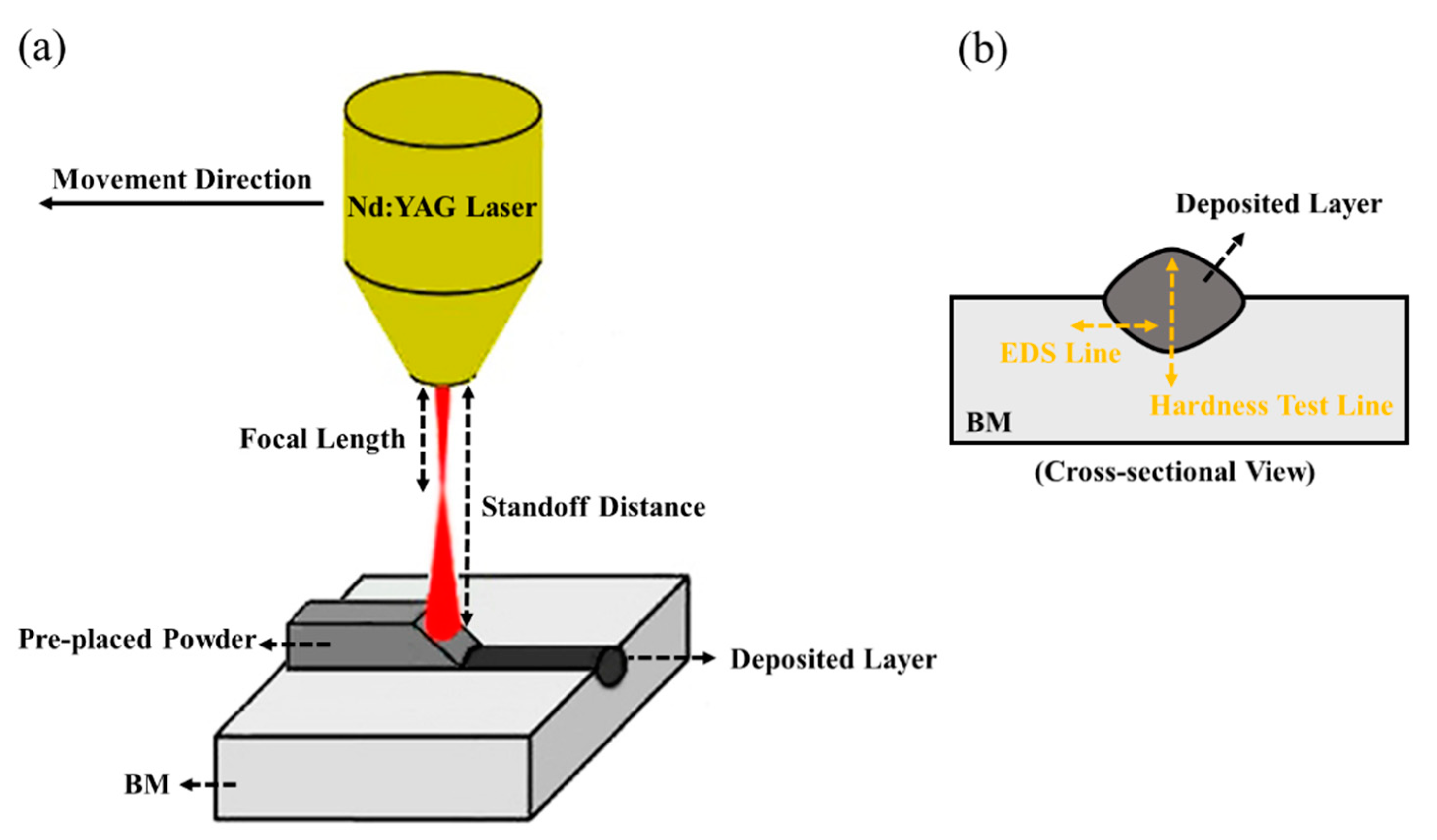
2. Materials and Methods
3. Results and Discussion
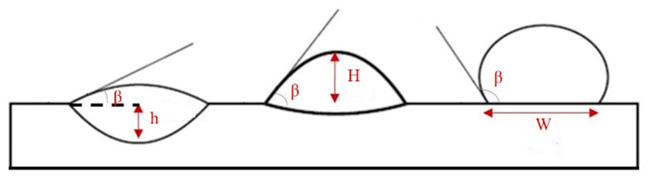
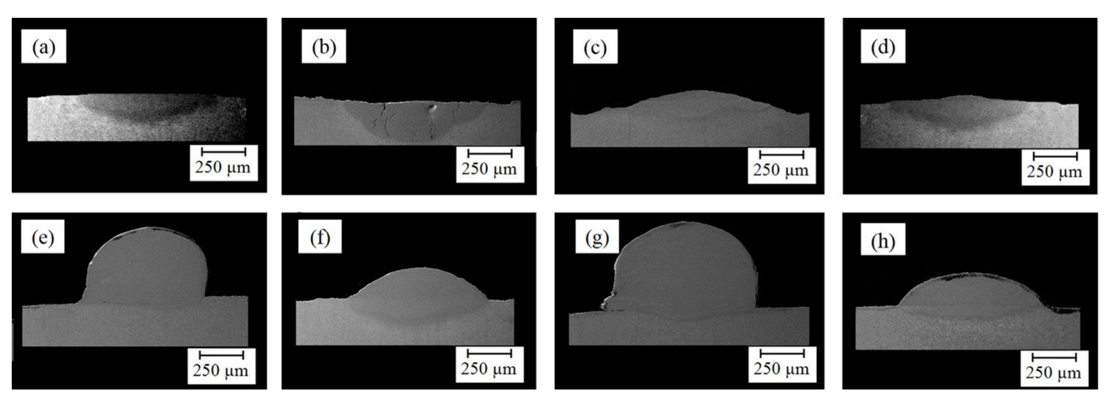
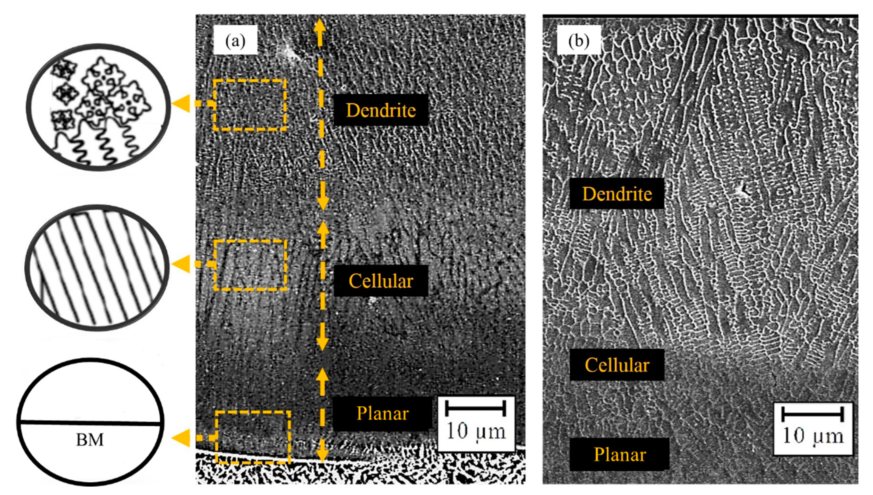
3.1. Geometrical Attributes and Microstructure of Layers
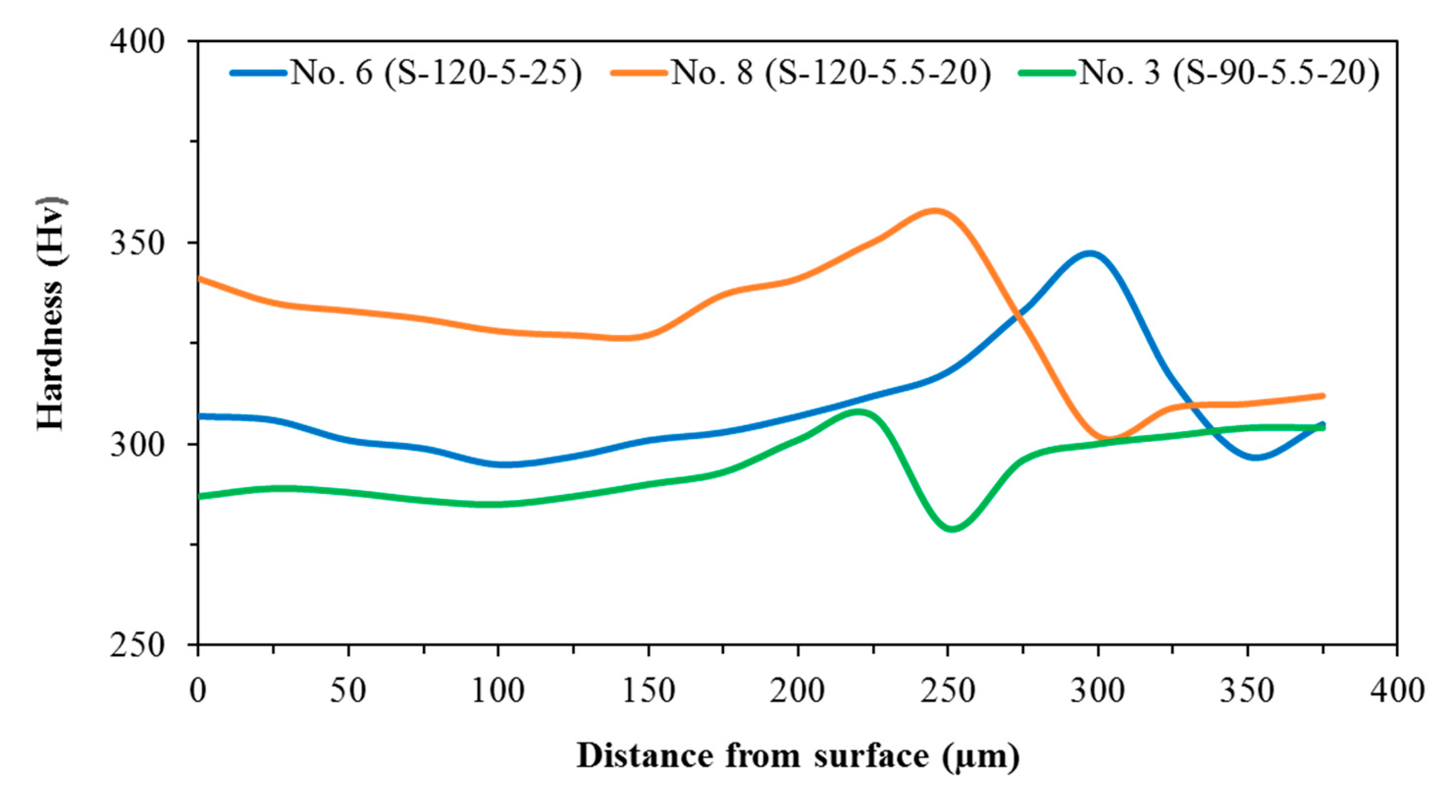
3.2. Microhardness of Layers
4. Conclusions
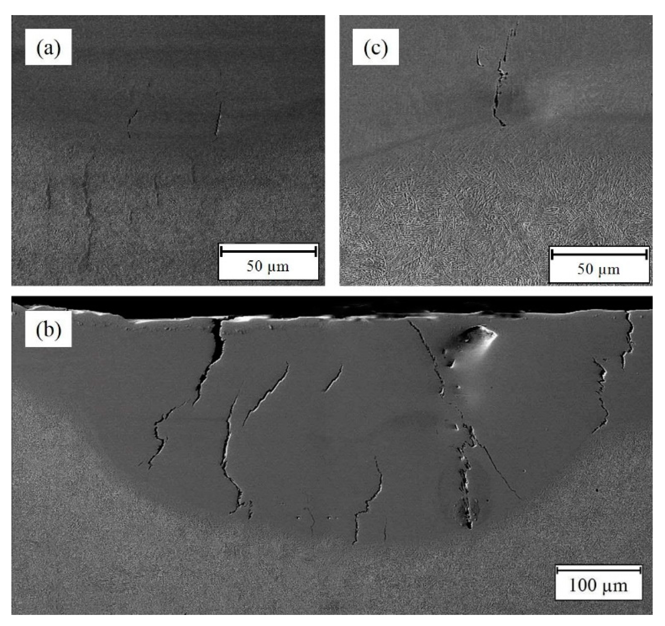
- The dilution and aspect ratio of the deposited layer reduced and the wetting angle raised with the increase in scanning speed and focal length. Meanwhile, the increment of frequency caused a reduction in the height but increase in the depth of the deposited layer. Consequently, the dilution and wetting angle respectively increased and reduced. It was determined that increasing the laser scanning speed could prevent cracking by reducing the temperature gradient (thermal stress) as well as improving the macroscopic characteristics of the samples through reduction of the dilution.
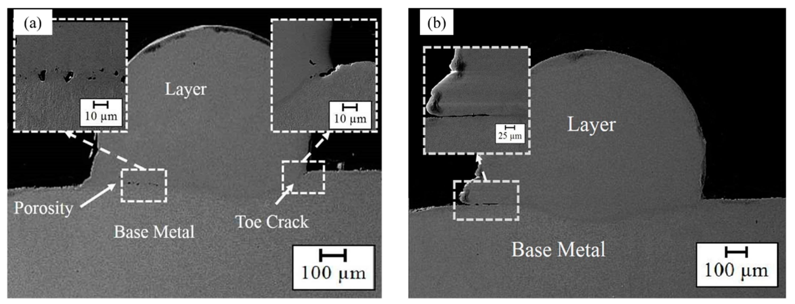
- Porosity and defects due to lack of fusion were found at a high scanning speed and lower frequency that featured the wetting angle higher than 80°. This is because the low overlapping factors and insufficient laser energy density that applied to a larger area induced a reduction in diffusion depth and increased the wetting angle.
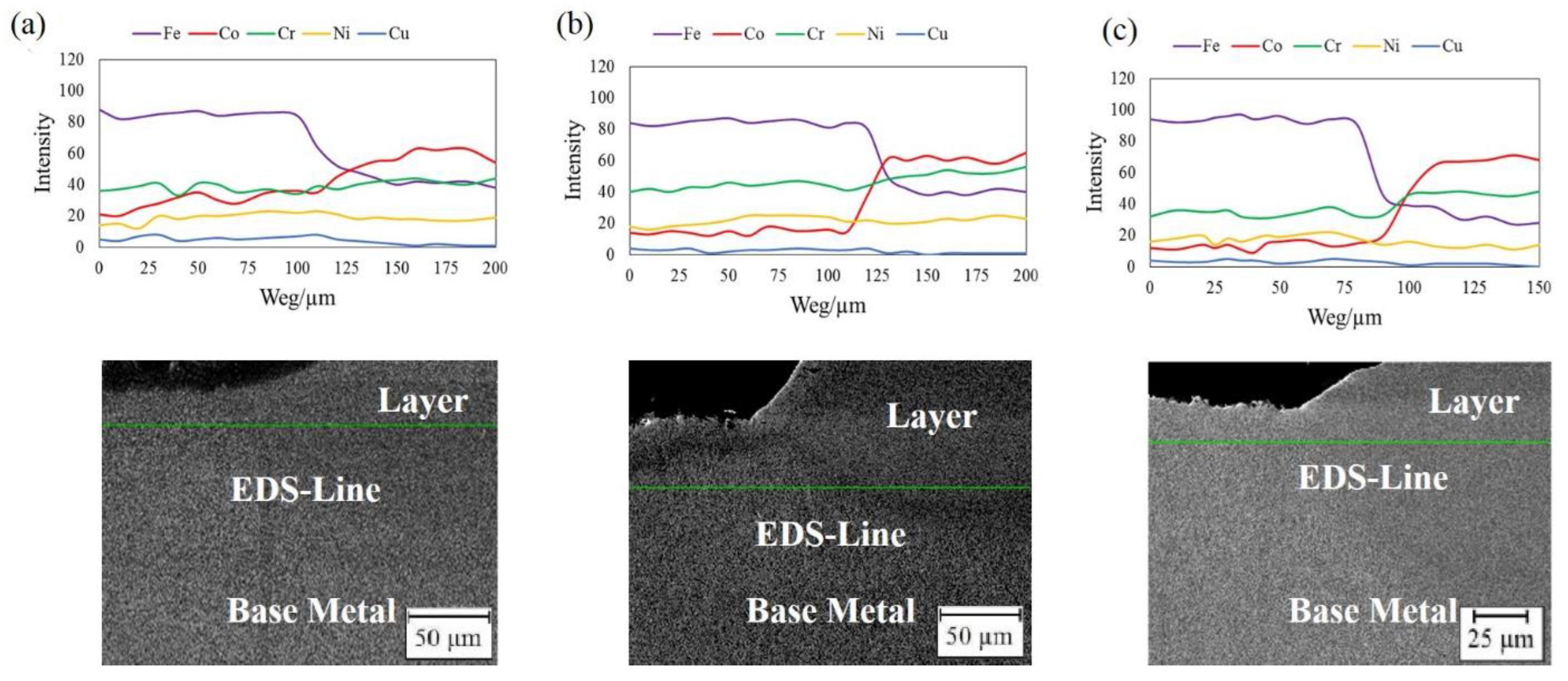
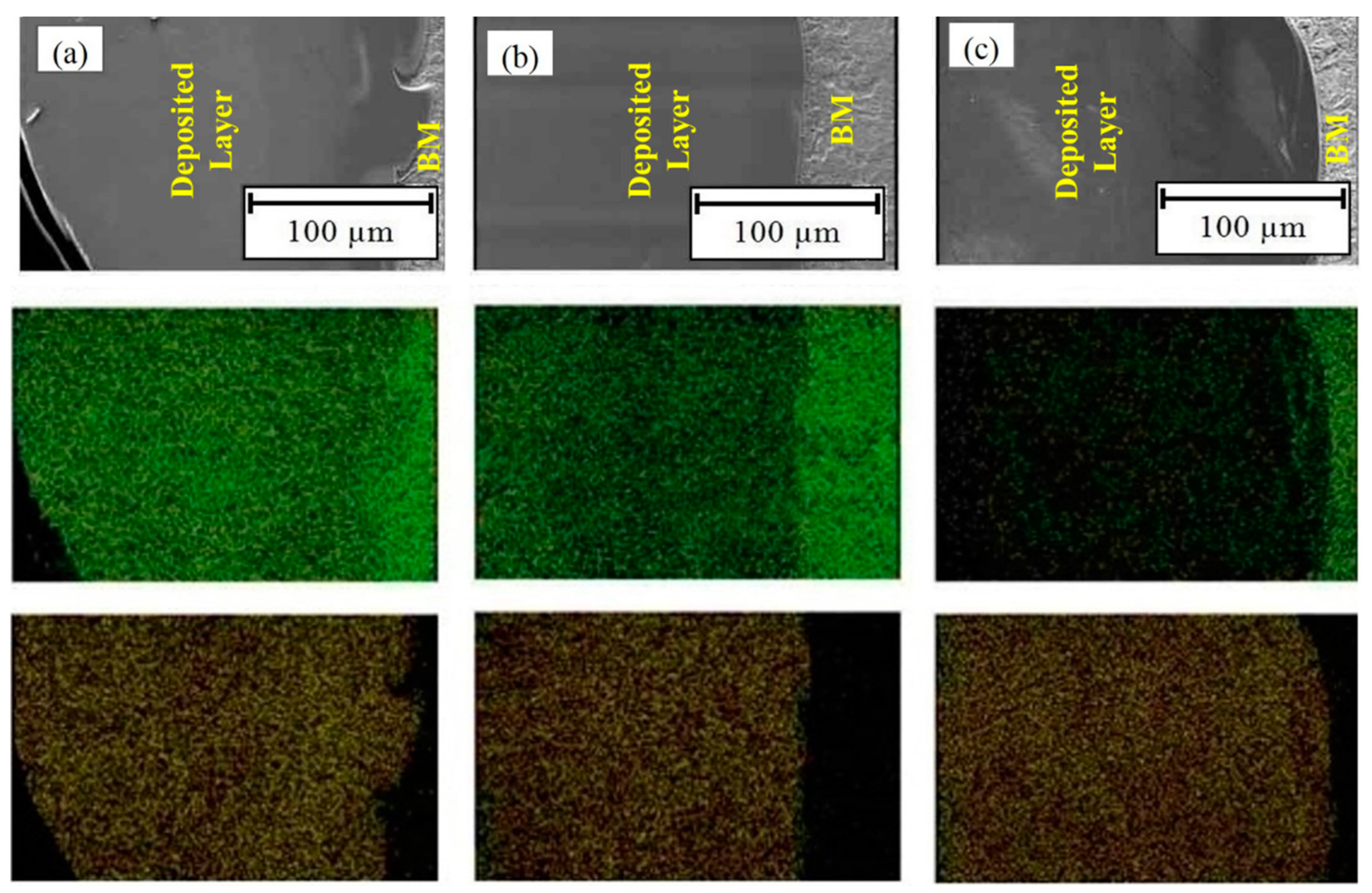
- The EDS results showed that the diffusion of elements from BM into a deposited layer and vice versa occurred to create a more uniform elements distribution. Furthermore, no particular secondary phase was found in the deposited zone at the BM-layer interface.
- Defect-free LMD layers possessing suitable geometrical attributes (wetting angle of 57° and dilution of 25.1%) and uniform distribution of microhardness property at the deposited layer and the surface (≈335 Hv) was achieved from a proper combination of laser scanning speed, focal length, and frequency of the LMD conditions.
Author Contributions
Funding
Institutional Review Board Statement
Informed Consent Statement
Conflicts of Interest
References
- Ghaderi, A.; Moghanni, H.; Dehghani, K. Microstructural Evolution and Mechanical Properties of Al0. 5CoCrFeNi High-Entropy Alloy after Cold Rolling and Annealing Treatments. J. Mater. Eng. Perform. 2021, 1–9. [Google Scholar] [CrossRef]
- Lashgari, H.R.; Kong, C.; Adabifiroozjaei, E.; Li, S. Microstructure, post thermal treatment response, and tribological properties of 3D printed 17-4 PH stainless steel. Wear 2020, 456–457, 203367. [Google Scholar] [CrossRef]
- Zai, L.; Zhang, C.; Wang, Y.; Guo, W.; Wellmann, D.; Tong, X.; Tian, Y. Laser Powder Bed Fusion of Precipitation-Hardened Martensitic Stainless Steels: A Review. Metals 2020, 10, 255. [Google Scholar] [CrossRef] [Green Version]
- Shahriari, A.; Khaksar, L.; Nasiri, A.; Hadadzadeh, A.; Amirkhiz, B.S.; Mohammadi, M. Microstructure and corrosion behavior of a novel additively manufactured maraging stainless steel. Electrochim. Acta 2020, 339, 135925. [Google Scholar] [CrossRef]
- Brown, B.; Newkirk, J.; Liou, F. Absorption of Nitrogen during Pulsed Wave L-PBF of 17-4 PH Steel. Materials 2021, 14, 560. [Google Scholar] [CrossRef] [PubMed]
- Yadollahi, A.; Shamsaei, N.; Thompson, S.M.; Elwany, A.; Bian, L. Effects of building orientation and heat treatment on fatigue behavior of selective laser melted 17-4 PH stainless steel. Int. J. Fatigue 2017, 94, 218–235. [Google Scholar] [CrossRef]
- Jiang, T.; Zhong, J.; Zhang, X.; Wang, W.; Guan, K. Hydrogen Embrittlement Induced Fracture of 17-4 PH Stainless Steel Valve Stem. Eng. Fail. Anal. 2020, 113, 104576. [Google Scholar] [CrossRef]
- Vilar, R. Laser cladding. J. Laser Appl. 1999, 11, 64–79. [Google Scholar] [CrossRef]
- Szala, M.; Chocyk, D.; Skic, A.; Kamiński, M.; Macek, W.; Turek, M. Effect of Nitrogen Ion Implantation on the Cavitation Erosion Resistance and Cobalt-Based Solid Solution Phase Transformations of HIPed Stellite 6. Materials 2021, 14, 2324. [Google Scholar] [CrossRef]
- Thawari, N.; Gullipalli, C.; Chandak, A.; Gupta, T.V.K. Influence of laser cladding parameters on distortion, thermal history and melt pool behaviour in multi-layer deposition of stellite 6: In-situ measurement. J. Alloys Compd. 2020, 860, 157894. [Google Scholar] [CrossRef]
- Moradi, M.; Hasani, A.; Beiranvand, Z.M.; Ashoori, A. Additive manufacturing of stellite 6 superalloy by direct laser metal deposition–Part 2: Effects of scanning pattern and laser power reduction in differrent layers. Opt. Laser Technol. 2020, 131, 106455. [Google Scholar] [CrossRef]
- Pauzi, A.A.; Ghazali, M.J.; W Zamri, W.F.H.; Rajabi, A. Wear characteristics of superalloy and hardface coatings in gas turbine applications–a review. Metals 2020, 10, 1171. [Google Scholar] [CrossRef]
- Gholipour, A.; Shamanian, M.; Ashrafizadeh, F. Microstructure and wear behavior of stellite 6 cladding on 17-4 PH stainless steel. J. Alloys Compd. 2011, 509, 4905–4909. [Google Scholar] [CrossRef]
- Deng, D.W.; Zhang, C.P.; Chen, R.; Xia, H.F. Microstructure and Microhardness of 17-4PH Deposited with Co-based Alloy Hardfacing Coating. Phys. Procedia 2013, 50, 177–184. [Google Scholar] [CrossRef] [Green Version]
- Yao, J.; Xin, B.; Gong, Y.; Cheng, G. Effect of Initial Temperature on the Microstructure and Properties of Stellite-6/Inconel 718 Functional Gradient Materials Formed by Laser Metal Deposition. Materials 2021, 14, 3609. [Google Scholar] [CrossRef] [PubMed]
- Kusmoko, A.; Dunne, D.; Li, H.J. Evaluation of Two Different Energy Inputs for Deposition of Stellite 6 by Laser Cladding on a Martensitic Stainless Steel Substrate. Adv. Mater. Res. 2015, 1119, 628–632. [Google Scholar] [CrossRef]
- Wahab, D.A.; Azman, A.H. Restoration of remanufacturable components using additive manufacturing. In Proceedings of the International Conference on Sustainable Design and Manufacturing; Springer: Berlin/Heidelberg, Germany, 2018; pp. 193–198. [Google Scholar]
- Zhang, Y.; Guo, Y.; Chen, Y.; Cao, Y.; Qi, H.; Yang, S. Microstructure and mechanical properties of Al-12Si alloys fabricated by ultrasonic-assisted laser metal deposition. Materials 2020, 13, 126. [Google Scholar] [CrossRef] [PubMed] [Green Version]
- Carrullo, J.C.Z.; Falcón, J.C.P.; Borrás, V.A. Influence of process parameters and initial microstructure on the oxidation resistance of Ti48Al2Cr2Nb coating obtained by laser metal deposition. Surf. Coatings Technol. 2019, 358, 114–124. [Google Scholar] [CrossRef]
- Rumman, R.; Lewis, D.A.; Hascoet, J.Y.; Quinton, J.S. Laser metal deposition and wire arc additive manufacturing of materials: An overview. Arch. Metall. Mater. 2019, 64, 467–473. [Google Scholar]
- Yan, L.; Chen, Y.; Liou, F. Additive manufacturing of functionally graded metallic materials using laser metal deposition. Addit. Manuf. 2020, 31, 100901. [Google Scholar] [CrossRef]
- Peighambardoust, N.S.; Alamdari, A.A.; Unal, U.; Motallebzadeh, A. In vitro biocompatibility evaluation of Ti1.5ZrTa0.5Nb0.5Hf0.5 refractory high-entropy alloy film for orthopedic implants: Microstructural, mechanical properties and corrosion behavior. J. Alloys Compd. 2021, 883, 160786. [Google Scholar] [CrossRef]
- Kang, X.; Dong, S.; Wang, H.; Yan, S.; Liu, X.; Xu, B. Effect of laser power on gradient microstructure of low-alloy steel built by laser melting deposition. Mater. Lett. 2020, 262, 127073. [Google Scholar] [CrossRef]
- Mazzucato, F.; Aversa, A.; Doglione, R.; Biamino, S.; Valente, A.; Lombardi, M. Influence of Process Parameters and Deposition Strategy on Laser Metal Deposition of 316L Powder. Metals 2019, 9, 1160. [Google Scholar] [CrossRef] [Green Version]
- Mashhuriazar, A.; Hakan Gur, C.; Sajuri, Z.; Omidvar, H. Effects of heat input on metallurgical behavior in HAZ of multi-pass and multi-layer welded IN-939 superalloy. J. Mater. Res. Technol. 2021, 15, 1590–1603. [Google Scholar] [CrossRef]
- Song, X.; Lei, J.; Gu, Z.; Zhou, S. Boosting wear properties of Inconel718 superalloy by uniform dispersing graphene nanoplatelets through laser melting deposition. J. Alloys Compd. 2020, 834, 155086. [Google Scholar] [CrossRef]
- Sun, S.D.; Fabijanic, D.; Annasamy, M.; Gallo, S.C.; Fordyce, I.; Paradowska, A.; Leary, M.; Easton, M.; Brandt, M. Microstructure, abrasive wear and corrosion characterisation of laser metal deposited Fe-30Cr-6Mo-10Ni-2.2 C alloy. Wear 2019, 438, 203070. [Google Scholar] [CrossRef]
- Wahab, D.A.; Azman, A.H. Additive manufacturing for repair and restoration in remanufacturing: An overview from object design and systems perspectives. Processes 2019, 7, 802. [Google Scholar]
- Farotade, G.A.; Adesina, O.S.; Popoola, A.P.I.; Pityana, S.L. Laser Cladding and Characterization of Ni–SiC–ZrB 2 Cermet Coatings on Ti–6Al–4V for High-Temperature Applications. Metallogr. Microstruct. Anal. 2019, 8, 349–358. [Google Scholar] [CrossRef]
- Muvvala, G.; Mullick, S.; Nath, A.K. Development of process maps based on molten pool thermal history during laser cladding of Inconel 718/TiC metal matrix composite coatings. Surf. Coatings Technol. 2020, 399, 126100. [Google Scholar] [CrossRef]
- Alizadeh-Sh, M.; Marashi, S.P.H.; Ranjbarnodeh, E.; Shoja-Razavi, R.; Oliveira, J.P. Dissimilar laser cladding of Inconel 718 powder on A-286 substrate: Microstructural evolution. J. Laser Appl. 2020, 32, 22048. [Google Scholar] [CrossRef]
- Zhang, Z.; Zhao, Y.; Chen, Y.; Su, Z.; Shan, J.; Wu, A.; Sato, Y.S.; Gu, H.; Tang, X. The role of the pulsed-wave laser characteristics on restraining hot cracking in laser cladding non-weldable nickel-based superalloy. Mater. Des. 2020, 198, 109346. [Google Scholar] [CrossRef]
- Anirudh, P.V.; Kumar, B.; Girish, G.; Shailesh, S.; Oyyaravelu, R.; Kannan, C.; Balan, A.S.S. Effect of Cryogenics-Assisted Low-Plasticity Burnishing on Laser-Clad Stellite 6 over SS420 Substrate. J. Mater. Eng. Perform. 2020, 29, 6861–6869. [Google Scholar] [CrossRef]
- Caballero, A.; Ding, J.; Ganguly, S.; Williams, S. Wire + Arc Additive Manufacture of 17-4 PH stainless steel: Effect of different processing conditions on microstructure, hardness, and tensile strength. J. Mater. Process. Technol. 2019, 268, 54–62. [Google Scholar] [CrossRef]
- Gonzalez-Val, C.; Pallas, A.; Panadeiro, V.; Rodriguez, A. A convolutional approach to quality monitoring for laser manufacturing. J. Intell. Manuf. 2020, 31, 789–795. [Google Scholar] [CrossRef] [Green Version]
- Alizadeh-Sh, M.; Marashi, S.P.H.; Ranjbarnodeh, E.; Shoja-Razavi, R. Laser cladding of Inconel 718 powder on a non-weldable substrate: Clad bead geometry-solidification cracking relationship. J. Manuf. Process. 2020, 56, 54–62. [Google Scholar] [CrossRef]
- De Baere, D.; Devesse, W.; De Pauw, B.; Hinderdael, M.; Guillaume, P. Evaluation of the diffuse reflectivity behaviour of the melt pool during the laser metal deposition process. In Proceedings of the International Congress on Applications of Lasers & Electro-Optics; Laser Institute of America: Orlando, FL, USA, 2016; Volume 2016, p. 506. [Google Scholar]
- Li, Q.; Chen, J.; Wang, X.; Liu, Y.; Jiang, K.; Yang, S.; Liu, Y. Process, microstructure and microhardness of GH3039 superalloy processed by laser metal wire deposition. J. Alloys Compd. 2021, 877, 160330. [Google Scholar] [CrossRef]
- Froend, M.; Riekehr, S.; Kashaev, N.; Klusemann, B.; Enz, J. Process development for wire-based laser metal deposition of 5087 aluminium alloy by using fibre laser. J. Manuf. Process. 2018, 34, 721–732. [Google Scholar] [CrossRef]
- Mashhuriazar, A.; Omidvar, H.; Gur, C.H.; Sajuri, Z. Effect of Welding Parameters on the Liquation Cracking Behavior of High-Chromium Ni-Based Superalloy. J. Mater. Eng. Perform. 2020, 29, 7843–7852. [Google Scholar] [CrossRef]
- Gharehbaghi, R.; Fatoba, O.S.; Akinlabi, E.T. Influence of scanning speed on the microstructure of deposited Al-Cu-Fe coatings on a titanium alloy substrate by laser metal deposition process. In Proceedings of the 2018 IEEE 9th International Conference on Mechanical and Intelligent Manufacturing Technologies (ICMIMT), Cape Town, South Africa, 10–13 February 2018; pp. 44–49. [Google Scholar]
- Cho, C.; Zhao, G.; Kwak, S.-Y.; Kim, C.B. Computational mechanics of laser cladding process. J. Mater. Process. Technol. 2004, 153, 494–500. [Google Scholar] [CrossRef]
- Nikam, S.H.; Jain, N.K.; Jhavar, S. Thermal modeling of geometry of single-track deposition in micro-plasma transferred arc deposition process. J. Mater. Process. Technol. 2016, 230, 121–130. [Google Scholar] [CrossRef]
- Yan, C.; Shi, Y.; Zhaoqing, L.; Wen, S.; Wei, Q. Selective Laser Sintering Additive Manufacturing Technology; Elsevier: Amsterdam, The Netherlands, 2020; ISBN 0081029942. [Google Scholar]
- Khalili, A.; Mojtahedi, M.; Qaderi, A.; Goodarzi, M.; Torkamany, M.J. Effect of pulse laser parameters on the microstructure of the in-situ Fe-TiC hard layer: Simulation and experiment. Opt. Laser Technol. 2021, 135, 106693. [Google Scholar] [CrossRef]
- Farnia, A.; Ghaini, F.M.; Sabbaghzadeh, J. Effects of pulse duration and overlapping factor on melting ratio in preplaced pulsed Nd: YAG laser cladding. Opt. Lasers Eng. 2013, 51, 69–76. [Google Scholar] [CrossRef]
- Bahiraei, M.; Mazaheri, Y.; Sheikhi, M.; Heidarpour, A. Mechanism of TiC formation in laser surface treatment of the commercial pure titanium pre-coated by carbon using PVD process. J. Alloys Compd. 2020, 834, 155080. [Google Scholar] [CrossRef]
- Torkamany, M.J.; Hamedi, M.J.; Malek, F.; Sabbaghzadeh, J. The effect of process parameters on keyhole welding with a 400 W Nd: YAG pulsed laser. J. Phys. D. Appl. Phys. 2006, 39, 4563. [Google Scholar] [CrossRef]
- Akbarpour, M.R.; Mashhuriazar, A.; Daryani, M. Experimental and Numerical Investigation on the Effect of the Tempcore Process Parameters on Microstructural Evolution and Mechanical Properties of Dual-Phase Steel Reinforcing Rebars. Met. Mater. Int. 2020, 27, 4074–4083. [Google Scholar] [CrossRef]
- Alkemade, S.J. The Weld Cracking Susceptibility of High Hardness Armour Steel; Defence Science and Technology Organization Canberra (Australia): Melbourne, Australia, 1996.
- Sun, Z.; Tan, X.; Wang, C.; Descoins, M.; Mangelinck, D.; Tor, S.B.; Jägle, E.A.; Zaefferer, S.; Raabe, D. Reducing hot tearing by grain boundary segregation engineering in additive manufacturing: Example of an AlxCoCrFeNi high-entropy alloy. Acta Mater. 2020, 204, 116505. [Google Scholar] [CrossRef]
- Meng, W.; Zhang, W.; Zhang, W.; Yin, X.; Cui, B. Fabrication of steel-Inconel functionally graded materials by laser melting deposition integrating with laser synchronous preheating. Opt. Laser Technol. 2020, 131, 106451. [Google Scholar] [CrossRef]
- Mashhuriazar, A.; Omidvar, H.; Sajuri, Z.; Gur, C.H.; Baghdadi, A.H. Effects of Pre-Weld Heat Treatment and Heat Input on Metallurgical and Mechanical Behaviour in HAZ of Multi-Pass Welded IN-939 Superalloy. Metals. 2020, 10, 1453. [Google Scholar] [CrossRef]
- Cao, L.; Chen, S.; Wei, M.; Guo, Q.; Liang, J.; Liu, C.; Wang, M. Effect of laser energy density on defects behavior of direct laser depositing 24CrNiMo alloy steel. Opt. Laser Technol. 2019, 111, 541–553. [Google Scholar] [CrossRef]
- Alizadeh-Sh, M.; Marashi, S.P.H.; Ranjbarnodeh, E.; Shoja-Razavi, R.; Oliveira, J.P. Prediction of solidification cracking by an empirical-statistical analysis for laser cladding of Inconel 718 powder on a non-weldable substrate. Opt. Laser Technol. 2020, 128, 106244. [Google Scholar] [CrossRef]
- Miná, É.M.; Da Silva, Y.C.; Dille, J.; Silva, C.C. The effect of dilution on microsegregation in AWS ER NiCrMo-14 alloy welding claddings. Metall. Mater. Trans. A 2016, 47, 6138–6147. [Google Scholar] [CrossRef]
- Borges, B.; Quintino, L.; Miranda, R.M.; Carr, P. Imperfections in laser clading with powder and wire fillers. Int. J. Adv. Manuf. Technol. 2010, 50, 175–183. [Google Scholar] [CrossRef]
- Mazzucato, F.; Forni, D.; Valente, A.; Cadoni, E. Laser Metal Deposition of Inconel 718 Alloy and As-built Mechanical Properties Compared to Casting. Materials 2021, 14, 437. [Google Scholar] [CrossRef] [PubMed]
- De Oliveira, U.; Ocelik, V.; De Hosson, J.T.M. Analysis of coaxial laser cladding processing conditions. Surf. Coatings Technol. 2005, 197, 127–136. [Google Scholar] [CrossRef]
- Xiang, S.; Luan, H.; Wu, J.; Yao, K.-F.; Li, J.; Liu, X.; Tian, Y.; Mao, W.; Bai, H.; Le, G.; et al. Microstructures and mechanical properties of CrMnFeCoNi high entropy alloys fabricated using laser metal deposition technique. J. Alloys Compd. 2019, 773, 387–392. [Google Scholar] [CrossRef]
- Sreeramagiri, P.; Bhagavatam, A.; Alrehaili, H.; Dinda, G. Direct laser metal deposition of René 108 single crystal superalloy. J. Alloys Compd. 2020, 838, 155634. [Google Scholar] [CrossRef]
- Wang, J.; Wu, W.J.; Jing, W.; Tan, X.; Bi, G.J.; Tor, S.B.; Leong, K.F.; Chua, C.K.; Liu, E. Improvement of densification and microstructure of ASTM A131 EH36 steel samples additively manufactured via selective laser melting with varying laser scanning speed and hatch spacing. Mater. Sci. Eng. A 2019, 746, 300–313. [Google Scholar] [CrossRef]
- Hosseini-Tayeb, H.; Rafiaei, S.M. Effects of lateral and vertical ultrasonic vibrations on the microstructure and microhardness of Stellite-6 coating deposited on Inconel 718 superalloy through laser metal deposition. Mater. Res. Express 2020, 7, 16531. [Google Scholar] [CrossRef]
- Ramakrishnan, A.; Dinda, G.P. Functionally graded metal matrix composite of Haynes 282 and SiC fabricated by laser metal deposition. Mater. Des. 2019, 179, 107877. [Google Scholar] [CrossRef]
- Zhang, X.; McMurtrey, M.D.; Wang, L.; O’Brien, R.C.; Shiau, C.-H.; Wang, Y.; Scott, R.; Ren, Y.; Sun, C. Evolution of Microstructure, Residual Stress, and Tensile Properties of Additively Manufactured Stainless Steel Under Heat Treatments. JOM 2020, 72, 4167–4177. [Google Scholar] [CrossRef]
- Savinov, R.; Wang, Y.; Shi, J. Microstructure and properties of CeO2-doped CoCrFeMnNi high entropy alloy fabricated by laser metal deposition. J. Manuf. Process. 2020, 56, 1245–1251. [Google Scholar] [CrossRef]
- Pilehrood, A.E.; Omidvar, H.; Shamsipur, A.; Sajuri, Z. Influence of transient liquid phase bonding followed by homogenization on the fatigue lifetimes of inconel 738 at elevated temperature. J. Manuf. Process. 2020, 55, 348–358. [Google Scholar] [CrossRef]
- Pilehrood, A.E.; Omidvar, H.; Shamsipur, A.; Khakian-Ghomi, M. Effect of transient liquid phase bonding followed by homogenization on the microstructure and hot tensile behavior of Inconel 738 superalloy. J. Manuf. Process. 2019, 48, 110–118. [Google Scholar] [CrossRef]
- Doroudi, A.; Pilehrood, A.E.; Mohebinia, M.; Dastgheib, A.; Rajabi, A.; Omidvar, H. Effect of the isothermal solidification completion on the mechanical properties of Inconel 625 transient liquid phase bond by changing bonding temperature. J. Mater. Res. Technol. 2020, 9, 10355–10365. [Google Scholar] [CrossRef]


| Alloys | Chemical Composition (wt %) | |||||||||
|---|---|---|---|---|---|---|---|---|---|---|
| Co | Cr | Si | W | Cu | Mn | Ni | Mo | C | Fe | |
| 17-4 PH (BM) | - | 15.80 | 0.44 | - | 3.85 | 0.28 | 3.77 | 0.21 | <0.10 | Bal. |
| Stellite 6 (deposited layer) | Bal. | 28.87 | 1.00 | 4.31 | - | 0.49 | 2.41 | <1.00 | 1.20 | 2.95 |
| Process Parameter | Value |
|---|---|
| Wavelength | 1064 nm |
| Maximum Laser Peak Power | 7 Kw |
| Nominal Laser Mean Power | 400 W |
| Laser Mean Power | 200 W |
| Pulse Shape | Square |
| Pulse Duration | 5 ms |
| Spatial Distribution | Gaussian |
| Standoff Distance | 5 mm |
| Flow Rate of Argon Gas | 10 L/min |
| Sample No. | Experimental Samples | Scanning Speed (mm/min) | Focal Length (mm) | Spot Size (mm) | Frequency (Hz) |
|---|---|---|---|---|---|
| 1 | S-90-5-20 | 90 | 5 | ~0.5 | 20 |
| 2 | S-90-5-25 | 90 | 5 | ~0.5 | 25 |
| 3 | S-90-5.5-20 | 90 | 5.5 | ~0.6 | 20 |
| 4 | S-90-5.5-25 | 90 | 5.5 | ~0.6 | 25 |
| 5 | S-120-5-20 | 120 | 5 | ~0.5 | 20 |
| 6 | S-120-5-25 | 120 | 5 | ~0.5 | 25 |
| 7 | S-120-5.5-20 | 120 | 5.5 | ~0.6 | 20 |
| 8 | S-120-5.5-25 | 120 | 5.5 | ~0.6 | 25 |
| Sample No. | Experimental Samples | Geometry Parameters | |||
|---|---|---|---|---|---|
| D (%) | ζ | B (°) | Schematic Image | ||
| 1 | S-90-5-20 | 89.8 ± 1.0 | 35 ± 3.7 | 3.6 ± 0.9 |  |
| 2 | S-90-5-25 | 100 ± 0 | - | 0 |  |
| 3 | S-90-5.5-20 | 43.9 ± 1.1 | 10.5 ± 1.2 | 18.4 ± 1.8 | 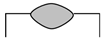 |
| 4 | S-90-5.5-25 | 75.3 ± 1.2 | 21 ± 2.4 | 6.9 ± 3.3 | 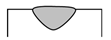 |
| 5 | S-120-5-20 | 10.9 ± 1.6 | 1.7 ± 0.1 | 84.9 ± 3.7 | 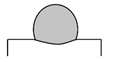 |
| 6 | S-120-5-25 | 35.3 ± 0.9 | 4.5 ± 0.1 | 41.1 ± 3.3 |  |
| 7 | S-120-5.5-20 | 10.1 ± 0.8 | 1.7 ± 0.1 | 89.0 ± 6.1 | 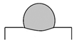 |
| 8 | S-120-5.5-20 | 25.1 ± 3.3 | 4.7 ± 0.1 | 57.0 ± 4.9 | 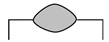 |
Publisher’s Note: MDPI stays neutral with regard to jurisdictional claims in published maps and institutional affiliations. |
© 2021 by the authors. Licensee MDPI, Basel, Switzerland. This article is an open access article distributed under the terms and conditions of the Creative Commons Attribution (CC BY) license (https://creativecommons.org/licenses/by/4.0/).
Share and Cite
Pilehrood, A.E.; Mashhuriazar, A.; Baghdadi, A.H.; Sajuri, Z.; Omidvar, H. Effect of Laser Metal Deposition Parameters on the Characteristics of Stellite 6 Deposited Layers on Precipitation-Hardened Stainless Steel. Materials 2021, 14, 5662. https://doi.org/10.3390/ma14195662
Pilehrood AE, Mashhuriazar A, Baghdadi AH, Sajuri Z, Omidvar H. Effect of Laser Metal Deposition Parameters on the Characteristics of Stellite 6 Deposited Layers on Precipitation-Hardened Stainless Steel. Materials. 2021; 14(19):5662. https://doi.org/10.3390/ma14195662
Chicago/Turabian StylePilehrood, Ali Ebrahimzadeh, Amirhossein Mashhuriazar, Amir Hossein Baghdadi, Zainuddin Sajuri, and Hamid Omidvar. 2021. "Effect of Laser Metal Deposition Parameters on the Characteristics of Stellite 6 Deposited Layers on Precipitation-Hardened Stainless Steel" Materials 14, no. 19: 5662. https://doi.org/10.3390/ma14195662
APA StylePilehrood, A. E., Mashhuriazar, A., Baghdadi, A. H., Sajuri, Z., & Omidvar, H. (2021). Effect of Laser Metal Deposition Parameters on the Characteristics of Stellite 6 Deposited Layers on Precipitation-Hardened Stainless Steel. Materials, 14(19), 5662. https://doi.org/10.3390/ma14195662