
Face Damage Growth of Sandwich Composites under Compressive Loading: Experiments, Analytical and Finite Element Modeling


Abstract
:1. Introduction
2. Materials and Methods
2.1. Experimental Setup
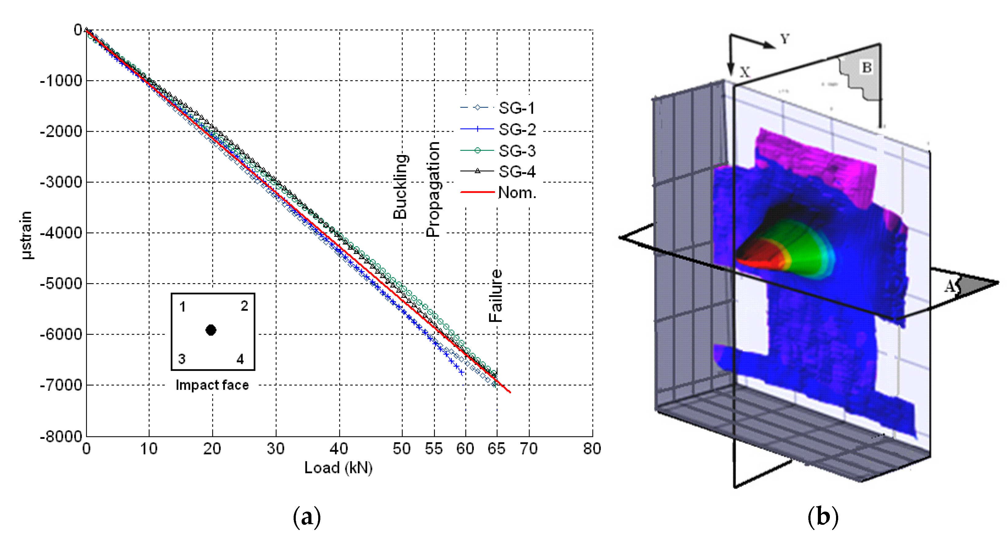
Compression after Impact (CAI) Test
2.2. Analytical Model
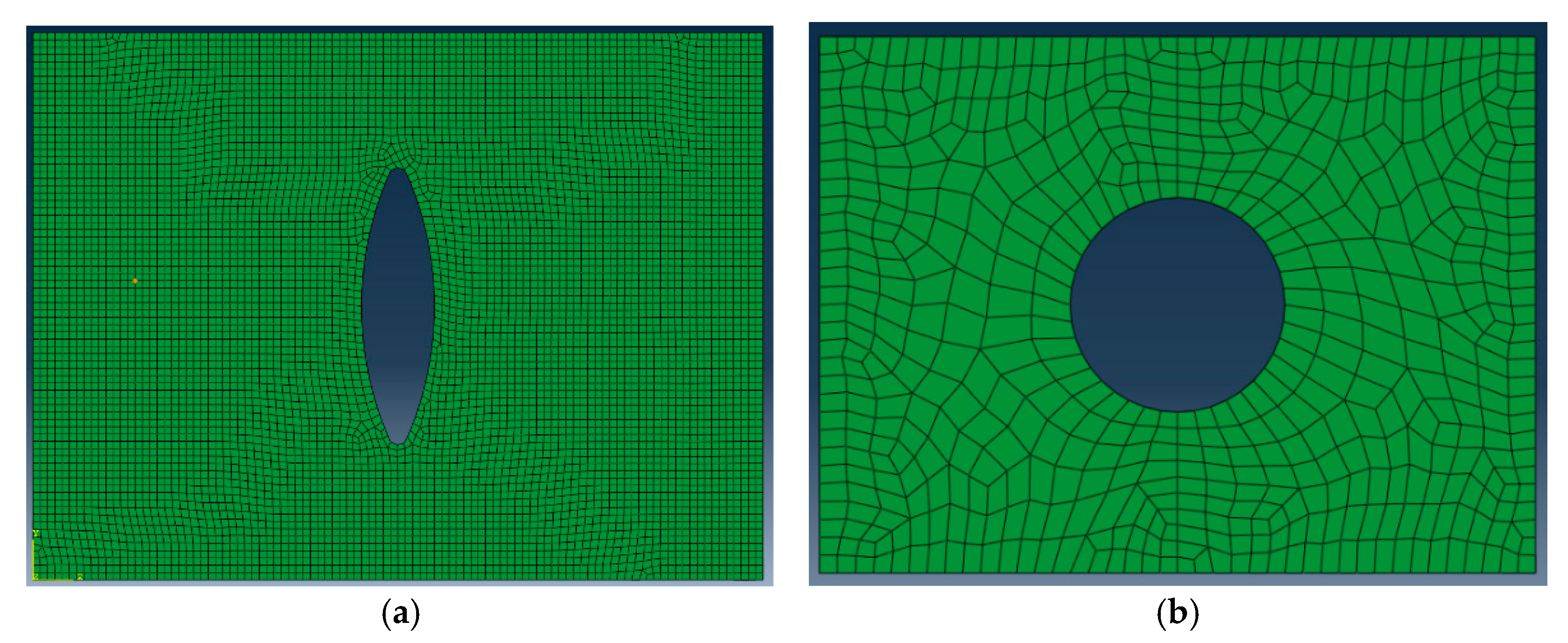
2.3. Finite Element Model
3. Results
4. Conclusions
Author Contributions
Funding
Institutional Review Board Statement
Informed Consent Statement
Data Availability Statement
Acknowledgments
Conflicts of Interest
References
- Bai, R.; Guo, J.; Lei, Z.; Liu, D.; Ma, Y.; Yan, C. Compression after Impact Behavior of Composite Foam-Core Sandwich Panels. Compos. Struct. 2019, 225, 111181. [Google Scholar] [CrossRef]
- Rubino, F.; Nisticò, A.; Tucci, F.; Carlone, P. Marine Application of Fiber Reinforced Composites: A Review. J. Mar. Sci. Eng. 2020, 8, 26. [Google Scholar] [CrossRef] [Green Version]
- Canale, G.; Andrews, S.; Rubino, F.; Maligno, A.; Citarella, R.; Weaver, P.M. Realistic Stacking Sequence Optimisation of an Aero-Engine Fan Blade-Like Structure Subjected to Frequency, Deformation and Manufacturing Constraints. Open Mech. Eng. J. 2018, 12, 151–163. [Google Scholar] [CrossRef]
- Carlone, P.; Rubino, F.; Paradiso, V.; Tucci, F. Multi-Scale Modeling and Online Monitoring of Resin Flow through Dual-Scale Textiles in Liquid Composite Molding Processes. Int. J. Adv. Manuf. Technol. 2018, 96, 2215–2230. [Google Scholar] [CrossRef]
- Rubino, F.; Esperto, V.; Tucci, F.; Carlone, P. Flow Enhancement in Liquid Composite Molding Processes by Online Microwave Resin Preheating. Polym. Eng. Sci. 2020, 60, 2377–2389. [Google Scholar] [CrossRef]
- Rubino, F.; Carlone, P. A Semi-Analytical Model to Predict Infusion Time and Reinforcement Thickness in VARTM and SCRIMP Processes. Polymers 2018, 11, 20. [Google Scholar] [CrossRef] [Green Version]
- Aleksendrić, D.; Bellini, C.; Carlone, P.; Ćirović, V.; Rubino, F.; Sorrentino, L. Neural-Fuzzy Optimization of Thick Composites Curing Process. Mater. Manuf. Process. 2019, 34, 262–273. [Google Scholar] [CrossRef]
- Tucci, F.; Bezerra, R.; Rubino, F.; Carlone, P. Multiphase Flow Simulation in Injection Pultrusion with Variable Properties. Mater. Manuf. Process. 2020, 35, 152–162. [Google Scholar] [CrossRef]
- Tucci, F.; Rubino, F.; Carlone, P. Strain and Temperature Measurement in Pultrusion Processes by Fiber Bragg Grating Sensors. AIP Conf. Proc. 2018, 1960, 020036. [Google Scholar] [CrossRef]
- Canale, G.; Weaver, P.M.; Rubino, F.; Maligno, A.; Citarella, R. Lay-up Optimization of Laminated Composites Using a Modified Branch and Bound Method. Open Mech. Eng. J. 2018, 12, 138–150. [Google Scholar] [CrossRef]
- Canale, G.; Kinawy, M.; Sathujoda, P.; Maligno, A.; Citarella, R.G. Moisture Absorption in Thick Composite Plates: Modelling and Experiments. Multidiscip. Model. Mater. Struct. 2019, 16, 439–447. [Google Scholar] [CrossRef]
- Elamin, M.; Li, B.; Tan, K.T. Compression after Impact Performance of Carbon-Fiber Foam-Core Sandwich Composites in Low Temperature Arctic Conditions. Compos. Struct. 2021, 261, 113568. [Google Scholar] [CrossRef]
- Gao, Y.; Hoo Fatt, M.S. Local Facesheet Pulse Buckling in a Curved, Composite Sandwich Panel. Compos. Struct. 2013, 104, 249–260. [Google Scholar] [CrossRef]
- Ma, M.; Yao, W.; Jiang, W.; Jin, W.; Chen, Y.; Li, P. Fatigue Behavior of Composite Sandwich Panels under Three Point Bending Load. Polym. Test. 2020, 91, 106795. [Google Scholar] [CrossRef]
- Zhang, C.; Tan, K.T. Low-Velocity Impact Response and Compression after Impact Behavior of Tubular Composite Sandwich Structures. Compos. Part B Eng. 2020, 193, 108026. [Google Scholar] [CrossRef]
- Rome, J.; Schubel, P.; Goyal, V.; Tuck-Lee, J. Predicting Compression-After-Impact Strength of Composite Sandwich Structures. In Proceedings of the 49th AIAA/ASME/ASCE/AHS/ASC Structures, Structural Dynamics, and Materials Conference, 16th AIAA/ASME/AHS Adaptive Structures Conference, 10th AIAA Non-Deterministic Approaches Conference, 9th AIAA Gossamer Spacecraft Forum, 4th AIAA Multidisciplinary Design Optimization Specialists Conference, Schaumburg, IL, USA, 7–10 April 2008; American Institute of Aeronautics and Astronautics: Reston, VA, USA, 2008. [Google Scholar]
- Kassapoglou, C. Buckling, Post-Buckling and Failure of Elliptical Delaminations in Laminates under Compression. Compos. Struct. 1988, 9, 139–159. [Google Scholar] [CrossRef]
- Kassapoglou, C.; Abbott, R. A Correlation Parameter for Predicting the Compressive Strength of Composite Sandwich Panels after Low Speed Impact. In Proceedings of the 29th Structures, Structural Dynamics and Materials Conference, Williamsburg, VA, USA, 18–20 April 1988; American Institute of Aeronautics and Astronautics: Reston, VA, USA, 18 April 1988. [Google Scholar]
- Shipsha, A.; Hallström, S.; Zenkert, D. Failure Mechanisms and Modelling of Impact Damage in Sandwich Beams—A 2D Approach: Part I—Experimental Investigation. J. Sandw. Struct. Mater. 2003, 5, 7–31. [Google Scholar] [CrossRef]
- Steven Johnson, W.; Lagace, P.; Masters, J.; Kardomateas, G. Postbuckling Characteristics in Delaminated Kevlar/Epoxy Laminates: An Experimental Study. J. Compos. Technol. Res. 1990, 12, 85. [Google Scholar] [CrossRef]
- Edgren, F.; Asp, L.E.; Bull, P.H. Compressive Failure of Impacted NCF Composite Sandwich Panels—Characterisation of the Failure Process. J. Compos. Mater. 2004, 38, 495–514. [Google Scholar] [CrossRef]
- Lomov, S.; Ivanov, D.; Verpoest, I.; Zako, M.; Kurashiki, T.; Nakai, H.; Hirosawa, S. Meso-FE Modelling of Textile Composites: Road Map, Data Flow and Algorithms. Compos. Sci. Technol. 2007, 67, 1870–1891. [Google Scholar] [CrossRef]
- Zhao, Z.; Liu, P.; Dang, H.; Chen, Y.; Zhang, C.; Pagani, A. Understanding the Critical Role of Boundary Conditions in Meso-Scale Finite Element Simulation of Braided Composites. Adv. Compos. Hybrid Mater. 2021. [Google Scholar] [CrossRef]
- Chai, H.; Babcock, C.D.; Knauss, W.G. One Dimensional Modelling of Failure in Laminated Plates by Delamination Buckling. Int. J. Solids Struct. 1981, 17, 1069–1083. [Google Scholar] [CrossRef] [Green Version]
- Chai, H.; Babcock, C.D. Two-Dimensional Modelling of Compressive Failure in Delaminated Laminates. J. Compos. Mater. 1985, 19, 67–98. [Google Scholar] [CrossRef]
- Flanagan, G. Two-Dimensional Delamination Growth in Composite Laminates under Compression Loading. In Composite Materials: Testing and Design (Eighth Conference); ASTM International: West Conshohocken, PA, USA, 1988; pp. 180–190. [Google Scholar]
- Butler, R.; Almond, D.P.; Hunt, G.W.; Hu, B.; Gathercole, N. Compressive Fatigue Limit of Impact Damaged Composite Laminates. Compos. Part A Appl. Sci. Manuf. 2007, 38, 1211–1215. [Google Scholar] [CrossRef]
- Rhead, A.T.; Butler, R.; Hunt, G.W. Post-Buckled Propagation Model for Compressive Fatigue of Impact Damaged Laminates. Int. J. Solids Struct. 2008, 45, 4349–4361. [Google Scholar] [CrossRef]
- Hunt, G.W.; Hu, B.; Butler, R.; Almond, D.P.; Wright, J.E. Nonlinear Modeling of Delaminated Struts. AIAA J. 2004, 42, 2364–2372. [Google Scholar] [CrossRef]
- Billups, E.K.; Cavalli, M.N. 2D Damping Predictions of Fiber Composite Plates: Layup Effects. Compos. Sci. Technol. 2008, 68, 727–733. [Google Scholar] [CrossRef]
- Adams, R.D.; Maheri, M.R. Dynamic Flexural Properties of Anisotropic Fibrous Composite Beams. Compos. Sci. Technol. 1994, 50, 497–514. [Google Scholar] [CrossRef]
- Williams, F.W.; Kennedy, D.; Butler, R.; Anderson, M.S. VICONOPT—Program for Exact Vibration and Buckling Analysis or Design of Prismatic Plate Assemblies. AIAA J. 1991, 29, 1927–1928. [Google Scholar] [CrossRef]
- Kennedy, D.; Williams, F.W.; Anderson, M.S. Buckling and Vibration Analysis of Laminated Panels Using VICONOPT. J. Aerosp. Eng. 1994, 7, 245–262. [Google Scholar] [CrossRef] [Green Version]
- Williams, F.; Kennedy, D.; Anderson, M. Analysis Features of VICONOPT, An Exact Buckling and Vibration Program for Prismatic Assemblies of Anisotropic Plates. In Proceedings of the 31st Structures, Structural Dynamics and Materials Conference, Long Beach, CA, USA, 2–4 April 1990; American Institute of Aeronautics and Astronautics: Reston, VA, USA, 1990. [Google Scholar]
- Butler, R.; Williams, F.W. Optimum Design Using Viconopt, a Buckling and Strength Constraint Program for Prismatic Assemblies of Anisotropic Plates. Comput. Struct. 1992, 43, 699–708. [Google Scholar] [CrossRef]
- Butler, R.; Williams, F.W. Optimum Buckling Design of Compression Panels Using VICONOPT. Struct. Optim. 1993, 6, 160–165. [Google Scholar] [CrossRef]
- Liu, W.; Butler, R.; Mileham, A.R.; Green, A.J. Bilevel Optimization and Postbuckling of Highly Strained Composite Stiffened Panels. AIAA J. 2006, 44, 2562–2570. [Google Scholar] [CrossRef]
- Williams, F.W.; Anderson, M.S.; Kennedy, D.; Butler, R.; Aston, G. User Manual for VICONOPT: An Exact Analysis and Optimum Design Program Covering the Buckling and Vibration of Prismatic Assemblies of Flat in-Plane Loaded, Anisotropic Plates, with Approximations for Discrete Supports, and Transverse Stiffeners; NASA: Hampton, VA, USA, 1990. [Google Scholar]
- Kinawy, M. Static and Fatigue Propagation of Buckle-Driven Delaminations under Bending and Compressive Loads. Ph.D. Thesis, University of Bath, Bath, UK, 2011. [Google Scholar]
- Choudhry, R.S.; Rhead, A.T.; Nielsen, M.W.D.; Butler, R. A Plate Model for Compressive Strength Prediction of Delaminated Composites. Compos. Struct. 2019, 210, 509–517. [Google Scholar] [CrossRef]
- Saseendran, V.; Carlsson, L.A.; Berggreen, C. Shear and Foundation Effects on Crack Root Rotation and Mode-Mixity in Moment- and Force-Loaded Single Cantilever Beam Sandwich Specimen. J. Compos. Mater. 2018, 52, 2537–2547. [Google Scholar] [CrossRef] [Green Version]
- Berggreen, C.; Saseendran, V.; Carlsson, L.A. A Modified DCB-UBM Test Method for Interfacial Fracture Toughness Characterization of Sandwich Composites. Eng. Fract. Mech. 2018, 203, 208–223. [Google Scholar] [CrossRef]
- Saseendran, V.; Berggreen, C.; Krueger, R. Mode Mixity Analysis of Face/Core Debonds in a Single Cantilever Beam Sandwich Specimen. J. Sandw. Struct. Mater. 2020, 22, 1879–1909. [Google Scholar] [CrossRef]
- Saseendran, V.; Berggreen, C. Mixed-Mode Fracture Evaluation of Aerospace Grade Honeycomb Core Sandwich Specimens Using the Double Cantilever Beam–Uneven Bending Moment Test Method. J. Sandw. Struct. Mater. 2020, 22, 991–1018. [Google Scholar] [CrossRef] [Green Version]
- Liu, W.; Butler, R. Buckling Optimization of Variable-Angle-Tow Panels Using the Infinite-Strip Method. AIAA J. 2013, 51, 1442–1449. [Google Scholar] [CrossRef]
- Milazzo, A.; Oliveri, V. Investigation of Buckling Characteristics of Cracked Variable Stiffness Composite Plates by an EXtended Ritz Approach. Thin-Walled Struct. 2021, 163, 107750. [Google Scholar] [CrossRef]


| Density [Mg/mm3] | Elastic Modulus [MPa] | Poisson’s Ratio |
|---|---|---|
| 0.3 × 10⁻⁹ | 390 | 0.3 |
| Fibers. | E11 (MPa) | E22 (MPa) | G12 (MPa) | ν12 | G1C (J/m2) | Thickness (mm) |
|---|---|---|---|---|---|---|
| Fibredux 913 GE5—Unidirectional Glass | 43,900 | 15,400 | 4290 | 0.28 | 225 | 0.142 |
| Hexply 913C HTA Unidirectional Carbon | 135,000 | 18,500 | 4970 | 0.29 | 225 | 0.134 |
| Fibers. | E33 (MPa) | G13 (MPa) | G23 (MPa) | ν13 | V23 |
|---|---|---|---|---|---|
| Fibredux 913 GE5—Unidirectional Glass | 10,400 | 3000 | 3000 | 0.28 | 0.28 |
| Hexply 913C HTA Unidirectional Carbon | 10,400 | 3000 | 3000 | 0.29 | 0.29 |
| Sublaminate Dimensions | Analytical | Experimental | ||
|---|---|---|---|---|
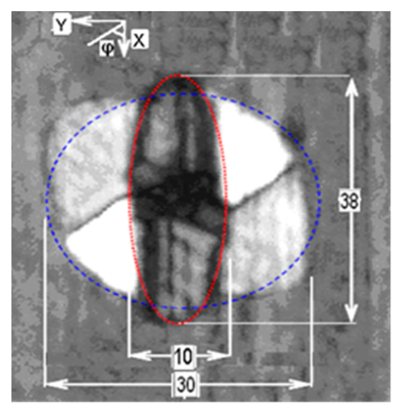
| a × b (mm) 18 × 30 | εC (10−6) | εth (10−6) | εC (10−6) | εprop (10−6) |
| 5310 | 5970 | 5050 | 5820 | |
Publisher’s Note: MDPI stays neutral with regard to jurisdictional claims in published maps and institutional affiliations. |
© 2021 by the authors. Licensee MDPI, Basel, Switzerland. This article is an open access article distributed under the terms and conditions of the Creative Commons Attribution (CC BY) license (https://creativecommons.org/licenses/by/4.0/).
Share and Cite
Kinawy, M.; Rubino, F.; Canale, G.; Citarella, R.; Butler, R. Face Damage Growth of Sandwich Composites under Compressive Loading: Experiments, Analytical and Finite Element Modeling. Materials 2021, 14, 5553. https://doi.org/10.3390/ma14195553
Kinawy M, Rubino F, Canale G, Citarella R, Butler R. Face Damage Growth of Sandwich Composites under Compressive Loading: Experiments, Analytical and Finite Element Modeling. Materials. 2021; 14(19):5553. https://doi.org/10.3390/ma14195553
Chicago/Turabian StyleKinawy, Moustafa, Felice Rubino, Giacomo Canale, Roberto Citarella, and Richard Butler. 2021. "Face Damage Growth of Sandwich Composites under Compressive Loading: Experiments, Analytical and Finite Element Modeling" Materials 14, no. 19: 5553. https://doi.org/10.3390/ma14195553
APA StyleKinawy, M., Rubino, F., Canale, G., Citarella, R., & Butler, R. (2021). Face Damage Growth of Sandwich Composites under Compressive Loading: Experiments, Analytical and Finite Element Modeling. Materials, 14(19), 5553. https://doi.org/10.3390/ma14195553