
Durability of a New Thermal Aerogel-Based Rendering System under Distinct Accelerated Aging Conditions

 ,
,  ,
,  ,
,  ,
,  and
and 
Abstract
:1. Introduction
2. Materials and Methods
2.1. Experimental Methodology
2.2. Materials
2.2.1. Mortar and Protective Coating System
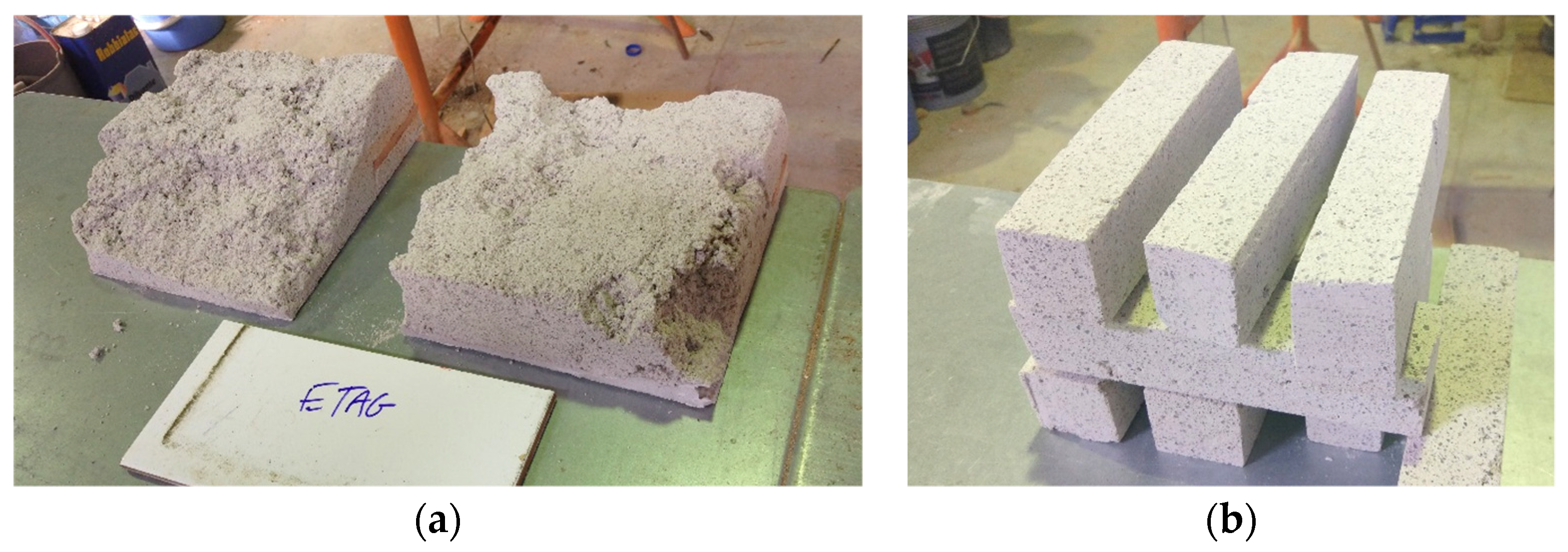
2.2.2. Collection and Preparation of the Specimens
2.3. Experimental Tests
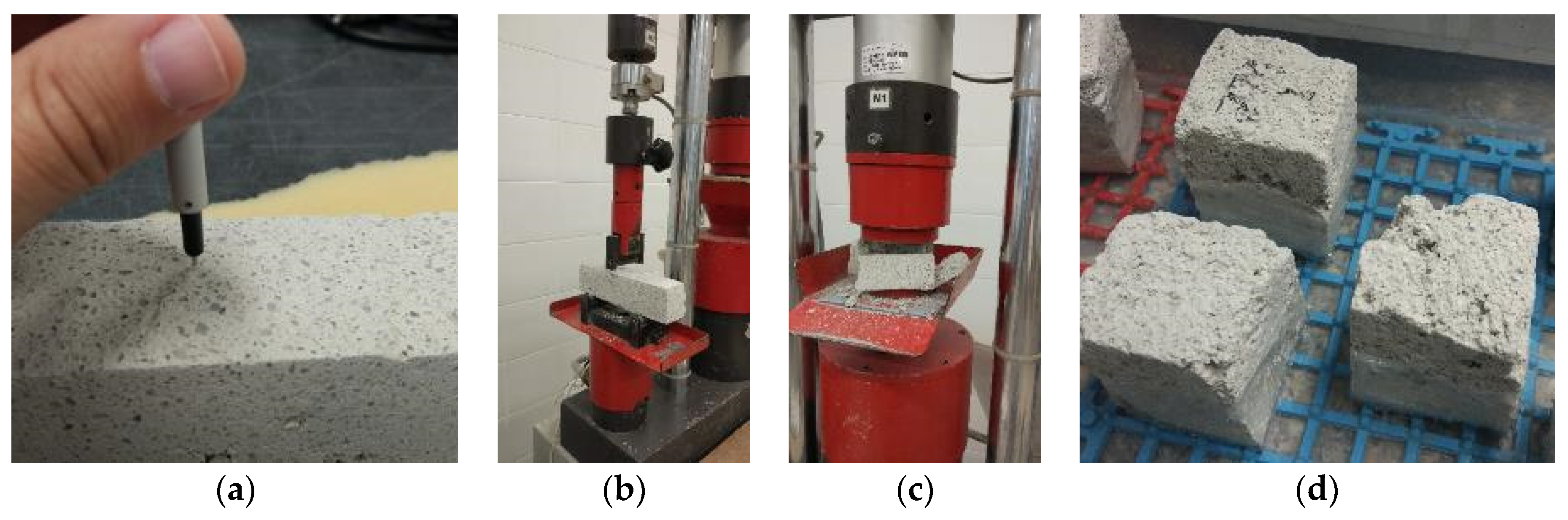
2.3.1. Mortar and Protective Coating System
Testing Procedures
Microstructural Testing Procedures
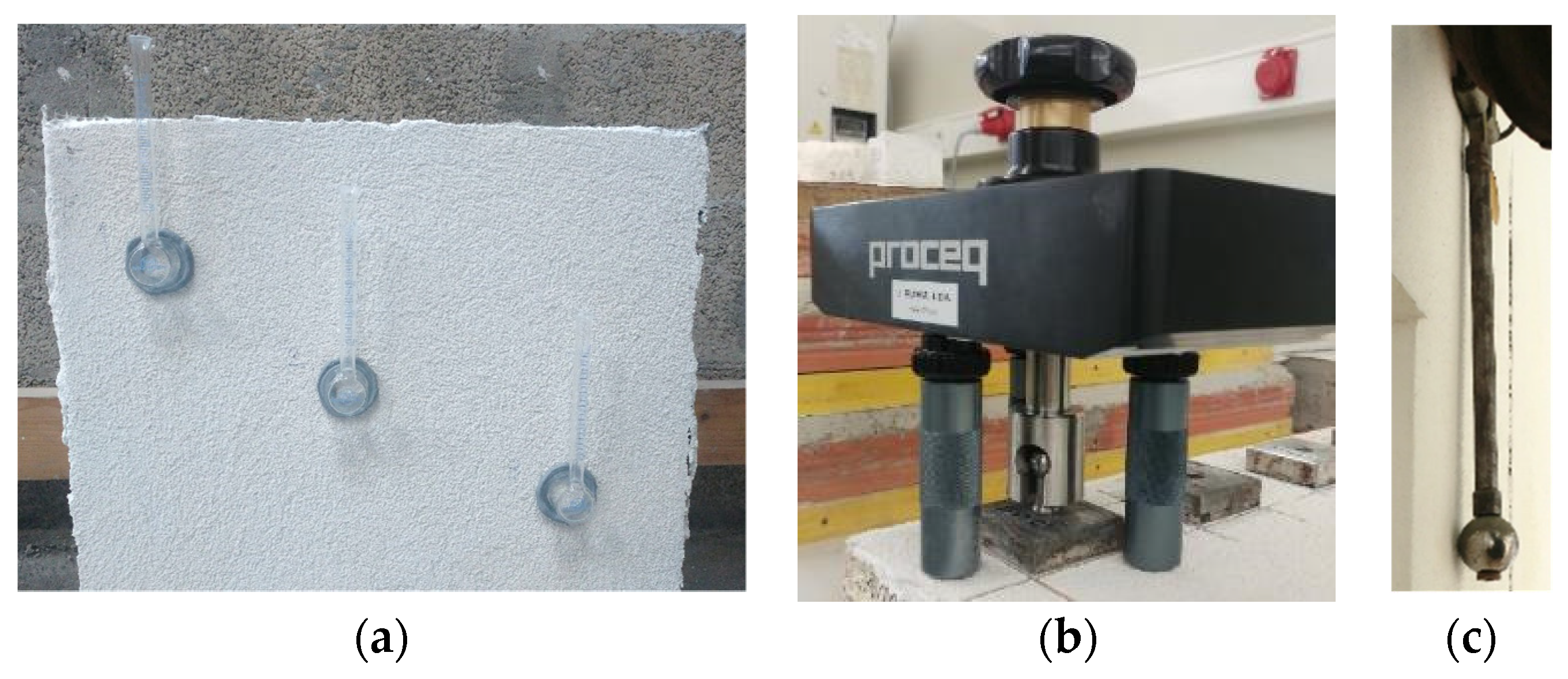
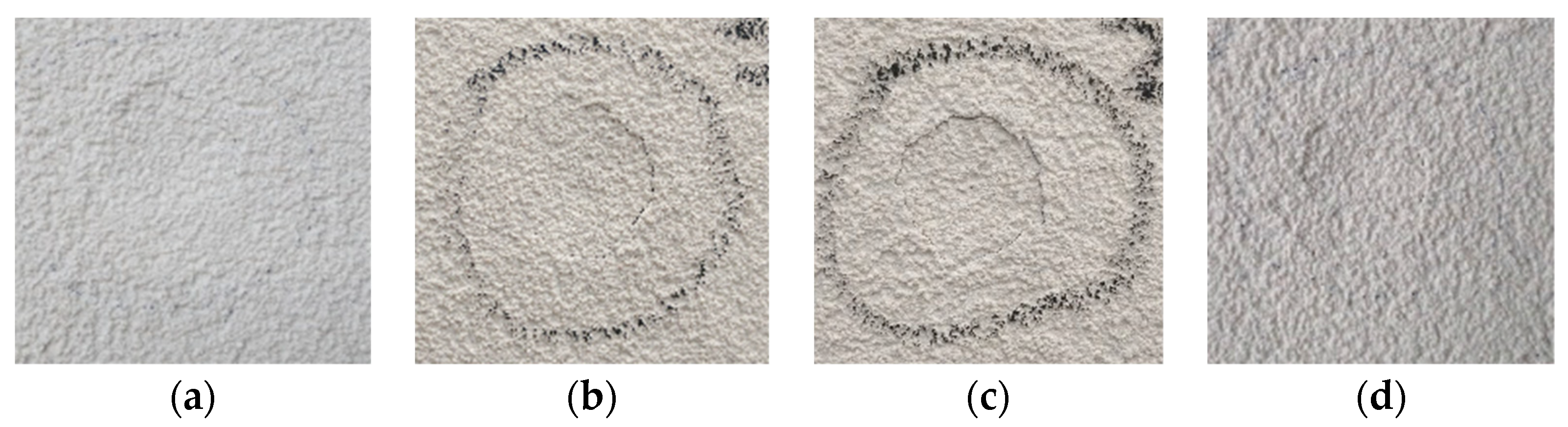
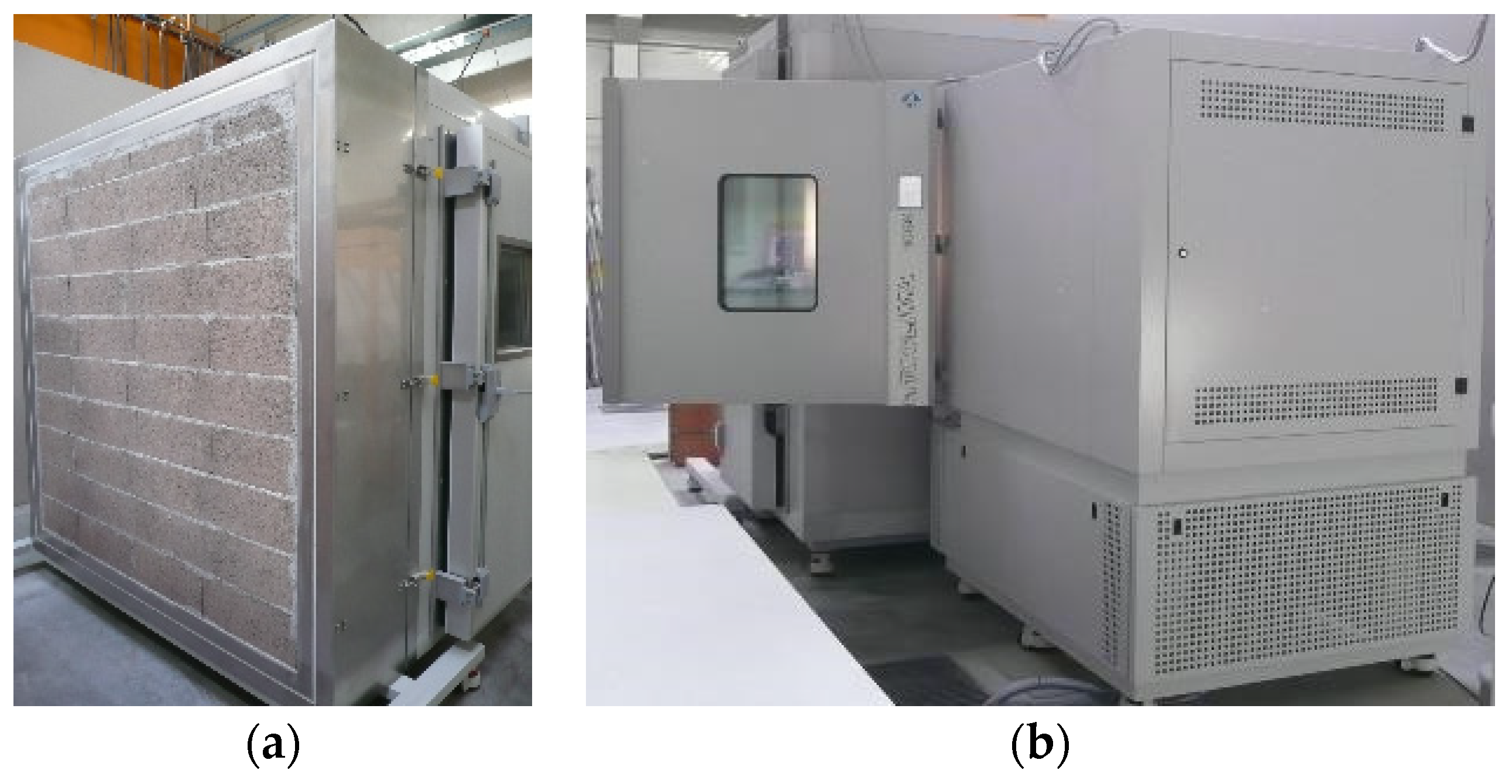
2.3.2. Wall Prototypes
3. Results and Discussion
3.1. Hardened-State Characterization
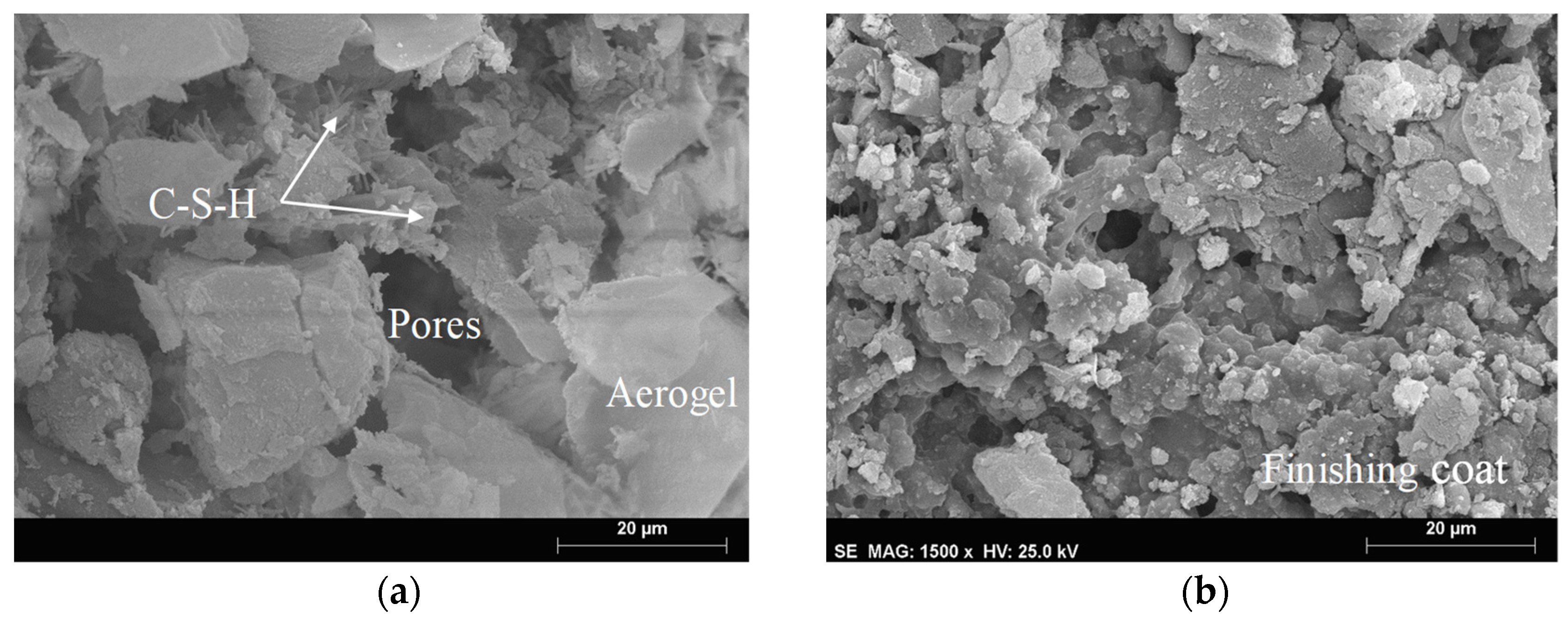
3.2. Microstructural Characterization
3.3. Discussion of the Results
4. Conclusions
Author Contributions
Funding
Institutional Review Board Statement
Informed Consent Statement
Data Availability Statement
Acknowledgments
Conflicts of Interest
References
- Van Breugel, K. How models can make a difference for a sustainable future of the building industry. Mater. Struct. Mater. Constr. 2018, 51, 161. [Google Scholar] [CrossRef] [PubMed] [Green Version]
- Pichler, C.; Metzler, G.; Niederegger, C.; Lackner, R. Thermo-mechanical optimization of porous building materials based on micromechanical concepts: Application to load-carrying insulation materials. Compos. Part B Eng. 2012, 43, 1015–1023. [Google Scholar] [CrossRef]
- ECEEE. Energy Performance of Buildings Directive; D. 2018/844EU; European Comission: Luxembourg, 2018. [Google Scholar]
- Ferrándiz-Mas, V.; Bond, T.; García-Alcocel, E.; Cheeseman, C.R. Lightweight mortars containing expanded polystyrene and paper sludge ash. Constr. Build. Mater. 2014, 61, 285–292. [Google Scholar] [CrossRef] [Green Version]
- Dixit, A.; Pang, S.D.; Kang, S.H.; Moon, J. Lightweight structural cement composites with expanded polystyrene (EPS) for enhanced thermal insulation. Cem. Concr. Compos. 2019, 102, 185–197. [Google Scholar] [CrossRef]
- Selvaranjan, K.; Navaratnam, S.; Gamage, J.C.P.H.; Thamboo, J.; Siddique, R.; Zhang, J.; Zhang, G. Thermal and environmental impact analysis of rice husk ash-based mortar as insulating wall plaster. Constr. Build. Mater. 2021, 283, 122744. [Google Scholar] [CrossRef]
- Leyton-Vergara, M.; Pérez-Fargallo, A.; Pulido-Arcas, J.; Cárdenas-Triviño, G.; Piggot-Navarrete, J. Influence of Granulometry on Thermal and Mechanical Properties of Cement Mortars Containing Expanded Perlite as a Lightweight Aggregate. Materials 2019, 12, 4013. [Google Scholar] [CrossRef] [PubMed] [Green Version]
- Senff, L.; Tobaldi, D.M.; Lucas, S.; Hotza, D.; Ferreira, V.M.; Labrincha, J.A. Formulation of mortars with nano-SiO2 and nano-TiO2 for degradation of pollutants in buildings. Compos. Part B Eng. 2013, 44, 40–47. [Google Scholar] [CrossRef]
- Stahl, T.; Brunner, S.; Zimmermann, M.; Ghazi Wakili, K. Thermo-hygric properties of a newly developed aerogel based insulation rendering for both exterior and interior applications. Energy Build. 2012, 44, 114–117. [Google Scholar] [CrossRef]
- Buratti, C.; Moretti, E.; Belloni, E.; Agosti, F. Development of Innovative Aerogel Based Plasters: Preliminary Thermal and Acoustic Performance Evaluation. Sustainability 2014, 6, 5839–5852. [Google Scholar] [CrossRef] [Green Version]
- Karim, A.N.; Johansson, P.; Kalagasidis, A.S. Super insulation plasters in renovation of buildings in Sweden: Energy efficiency and possibilities with new building materials. IOP Conf. Ser. Earth Environ. Sci. 2020, 588, 042050. [Google Scholar] [CrossRef]
- Fantucci, S.; Fenoglio, E.; Grosso, G.; Serra, V.; Perino, M.; Marino, V.; Dutto, M. Development of an aerogel-based thermal coating for the energy retrofit and the prevention of condensation risk in existing buildings. Sci. Technol. Built Environ. 2019, 25, 1178–1186. [Google Scholar] [CrossRef] [Green Version]
- Cuce, E.; Cuce, P.M.; Wood, C.J.; Riffat, S.B. Toward aerogel based thermal superinsulation in buildings: A comprehensive review. Renew. Sustain. Energy Rev. 2014, 34, 273–299. [Google Scholar] [CrossRef]
- Liu, Z.-H.; Ding, Y.-D.; Wang, F.; Deng, Z.-P. Thermal insulation material based on SiO2 aerogel. Constr. Build. Mater. 2016, 122, 548–555. [Google Scholar] [CrossRef]
- Koebel, M.; Rigacci, A.; Achard, P. Aerogel-based thermal superinsulation: An overview. J. Sol-Gel Sci. Technol. 2012, 63, 315–339. [Google Scholar] [CrossRef] [Green Version]
- De Fátima Júlio, M.; Ilharco, L.M.; Soares, A.; Flores-Colen, I.; de Brito, J. Silica-based aerogels as aggregates for cement-based thermal renders. Cem. Concr. Compos. 2016, 72, 309–318. [Google Scholar] [CrossRef]
- Ximenes, S.; Silva, A.; Soares, A.; Flores-Colen, I.; De Brito, J. Parametric Analysis to Study the Influence of Aerogel-Based Renders’ Components on Thermal and Mechanical Performance. Materials 2016, 9, 336. [Google Scholar] [CrossRef] [PubMed] [Green Version]
- Lucchi, E.; Becherini, F.; Di Tuccio, M.C.; Troi, A.; Frick, J.; Roberti, F.; Hermann, C.; Fairnington, I.; Mezzasalma, G.; Pockelé, L.; et al. Thermal performance evaluation and comfort assessment of advanced aerogel as blown-in insulation for historic buildings. Build. Environ. 2017, 122, 258–268. [Google Scholar] [CrossRef]
- Ganobjak, M.; Brunner, S.; Wernery, J. Aerogel materials for heritage buildings: Materials, properties and case studies. J. Cult. Herit. 2020, 42, 81–98. [Google Scholar] [CrossRef]
- Frick, J.; Stipetić, M.; Mielich, O.; Garrecht, H. Studies on thermal performance of advanced aerogel-based materials. In Smart Innovation, Systems and Technologies; Springer: Singapore, 2020; pp. 641–649. [Google Scholar]
- Lamy-Mendes, A.; Pontinha, A.D.R.; Alves, P.; Santos, P.; Durães, L. Progress in silica aerogel-containing materials for buildings’ thermal insulation. Constr. Build. Mater. 2021, 286, 122815. [Google Scholar] [CrossRef]
- Fantucci, S.; Fenoglio, E.; Serra, V.; Perino, M.; Dutto, M.; Marino, V. Hygrothermal Characterization of High-Performance Aerogel-Based Internal Plaster. In Sustainability in Energy and Buildings; Littlewood, J., Howlett, R.J., Capozzoli, A., Jain, L.C., Eds.; Springer: Singapore, 2020; pp. 259–268. [Google Scholar]
- Johansson, P.; Wahlgren, P. Interior insulation using super insulation materials: Saving energy and space. IOP Conf. Ser. Earth Environ. Sci. 2020, 588, 052017. [Google Scholar] [CrossRef]
- Madyan, O.A.; Fan, M.; Feo, L.; Hui, D. Physical properties of clay aerogel composites: An overview. Compos. Part B Eng. 2016, 102, 29–37. [Google Scholar] [CrossRef]
- Sun, M.; Zou, C.; Xin, D. Pore structure evolution mechanism of cement mortar containing diatomite subjected to freeze-thaw cycles by multifractal analysis. Cem. Concr. Compos. 2020, 114, 103731. [Google Scholar] [CrossRef]
- Esmaeeli, H.S.; Farnam, Y.; Bentz, D.P.; Zavattieri, P.D.; Weiss, W.J. Numerical simulation of the freeze–thaw behavior of mortar containing deicing salt solution. Mater. Struct. Mater. Constr. 2017, 50, 96. [Google Scholar] [CrossRef] [Green Version]
- Xiong, H.; Yuan, K.; Xu, J.; Wen, M. Pore structure, adsorption, and water absorption of expanded perlite mortar in external thermal insulation composite system during aging. Cem. Concr. Compos. 2021, 116, 103900. [Google Scholar] [CrossRef]
- Sousa-Coutinho, J. Improvement of Concrete Durability by Formwork Treatment; Civil Engineering, University of Porto: Porto, Portugal, 1998. [Google Scholar]
- McCurrich, L.H. Permeability Testing of Site Concrete. A Review of Methods and Experience; Technical Report; Concrete Society: London, UK, 1987. [Google Scholar]
- Addleson, L. Buildings Failures: A Guide to Diagnosis, Remedy and Prevention, 3rd ed.; Butterworth Architecture: Oxford, UK, 1992. [Google Scholar]
- Aguiar, J.; Cabrita, A.; Appleton, J. Support Guide to the Rehabilitation of Residential Buildings; INH & LNEC: Lisboa, Portugal, 2002; ISBN 978-972-492081-8.
- Palomo, A.; Blanco-Varela, M.T.; Martinez-Ramirez, S.; Puertas, F.; Fortes, C. Historic Mortars: Characterization and Durability. New Tendencies for Research. In Proceedings of the 9th International Congress on Deterioration and Conservation of Stone, Venice, Italy, 19–24 June 2002; Fassina, V., Ed.; Elsevier: Amsterdam, The Netherlands, 2000; pp. 235–243. [Google Scholar]
- Van Hees, R.; Veiga, R.; Slížková, Z. Consolidation of renders and plasters. Mater. Struct. Mater. Constr. 2017, 50, 65. [Google Scholar] [CrossRef] [Green Version]
- Pavía, S.; Treacy, E. A comparative study of the durability and behaviour of fat lime and feebly-hydraulic lime mortars. Mater. Struct. Mater. Constr. 2006, 39, 391–398. [Google Scholar] [CrossRef]
- Ihara, T.; Jelle, B.P.; Gao, T.; Gustavsen, A. Aerogel granule aging driven by moisture and solar radiation. Energy Build. 2015, 103, 238–248. [Google Scholar] [CrossRef]
- Berardi, U.; Nosrati, R.H. Long-term thermal conductivity of aerogel-enhanced insulating materials under different laboratory aging conditions. Energy 2018, 147, 1188–1202. [Google Scholar] [CrossRef]
- Pereira, M.C.; Soares, A.; Flores-Colen, I.; Correia, J.R. Influence of Exposure to Elevated Temperatures on the Physical and Mechanical Properties of Cementitious Thermal Mortars. Appl. Sci. 2020, 10, 2200. [Google Scholar] [CrossRef] [Green Version]
- Maia, J.; Pedroso, M.; Ramos, N.M.M.; Pereira, P.F.; Flores-Colen, I.; Gomes, M.G.; Silva, L. Hygrothermal performance of a new thermal aerogel-based render under distinct climatic conditions. Energy Build. 2021, 243, 111001. [Google Scholar] [CrossRef]
- Madyan, O.A.; Fan, M.; Feo, L.; Hui, D. Enhancing mechanical properties of clay aerogel composites: An overview. Compos. Part B Eng. 2016, 98, 314–329. [Google Scholar] [CrossRef]
- Pedroso, M.; Flores-Colen, I.; Silvestre, J.D.; Gomes, M.G.; Silva, L.; Ilharco, L. Physical, mechanical, and microstructural characterisation of an innovative thermal insulating render incorporating silica aerogel. Energy Build. 2020, 211, 109793. [Google Scholar] [CrossRef]
- Maia, J.; Ramos, N.M.M.; Veiga, R. A new durability assessment methodology of thermal mortars applied in multilayer rendering systems. Constr. Build. Mater. 2019, 222, 654–663. [Google Scholar] [CrossRef]
- De Sousa, R.; Sousa, H.; Silva, L.; Flores-Colen, I.; Pedroso, M. Development of a Wall System Made with Thermally Optimized Masonry and Super Insulation Mortar Render. Mason. Int. 2019, 32, 3–14. [Google Scholar]
- Enersens. Product Data Sheet: Aerogel Kwark. 2021. Available online: http://enersens.eu/kwark/ (accessed on 2 February 2021).
- Saint-Gobain Weber. Technical Datasheet: Webertherm Pro. 2019. Available online: https://www.pt.weber/revestimento-e-renovacao-de-fachadas/webertherm-pro (accessed on 2 February 2021).
- Saint-Gobain Weber. Technical Datasheet: Weberplast Decor Plus. 2021. Available online: https://www.pt.weber/revestimento-e-renovacao-de-fachadas/weberplast-decor-plus (accessed on 2 February 2021).
- Pedroso, M.; Flores-Colen, I.; Silvestre, J.D.; Gomes, M.G.; Silva, L.; Sequeira, P.; de Brito, J. Characterisation of a multilayer external wall thermal insulation system. Application in a Mediterranean climate. J. Build. Eng. 2020, 30, 101265. [Google Scholar] [CrossRef]
- CEN. EN 1015 Methods of Test for Mortar for Masonry, Part 10: Determination of Dry Bulk Density of Hardened Mortar; European Committee for Standardization: Brussels, Belgium, 1999. [Google Scholar]
- ASTM. E1876-15 Standard Test Method for Dynamic Young’s Modulus, Shear Modulus, and Poisson’s Ratio by Impulse Excitation of Vibration; ASTM International: West Conshohocken, PA, USA, 2015; pp. 1–15. [Google Scholar]
- CEN. EN 1015 Methods of Test for Mortar for Masonry, Part 11: Determination of Flexural and Compressive Strength of Hardened Mortar; European Committee for Standardization: Brussels, Belgium, 1999. [Google Scholar]
- CEN. EN 1015 Methods of Test for Mortar for Masonry, Part 18: Determination of Water Absorption Coefficient Due to Capillary Action of Hardened Mortar; European Commitee for Standardization: Brussels, Belgium, 2002. [Google Scholar]
- Gupta, P.; Verma, C.; Maji, P.K. Flame retardant and thermally insulating clay based aerogel facilitated by cellulose nanofibers. J. Supercrit. Fluids 2019, 152, 104537. [Google Scholar] [CrossRef]
- Sing, K.S.W.; Everett, D.H.; Haul, R.A.W.; Moscou, L.; Pierotti, R.A.; Rouquerol, J.; Siemieniewska, T. Reporting Physisorption Data for Gas/Solid Systems. In Handbook of Heterogeneous Catalysis; Wiley: Hoboken, NJ, USA, 2008; pp. 1217–1230. [Google Scholar]
- Sing, K.S.W. Reporting physisorption data for gas/solid systems with special reference to the determination of surface area and porosity (Recommendations 1984). J. Pure Appl. Chem. 1985, 57, 603. [Google Scholar] [CrossRef]
- Washburn, E.W. Note on a Method of Determining the Distribution of Pore Sizes in a Porous Material. Proc. Natl. Acad. Sci. USA 1921, 7, 115–116. [Google Scholar] [CrossRef] [PubMed] [Green Version]
- Kooshkaki, A.; Eskandari-Naddaf, H. Effect of porosity on predicting compressive and flexural strength of cement mortar containing micro and nano-silica by multi-objective ANN modeling. Constr. Build. Mater. 2019, 212, 176–191. [Google Scholar] [CrossRef]
- Scrivener, K.; Snellings, R.; Lothenbach, B. A Practical Guide to Microstructural Analysis of Cementitious Materials; CRC Press: Boca Raton, FL, USA, 2016. [Google Scholar]
- Júlio, M.d.F.; Soares, A.; Ilharco, L.M.; Flores-Colen, I.; de Brito, J. Aerogel-based renders with lightweight aggregates: Correlation between molecular/pore structure and performance. Constr. Build. Mater. 2016, 124, 485–495. [Google Scholar] [CrossRef]
- Mehta, P.K.; Monteiro, J.M. Concrete: Microstructure Properties and Materials, 3rd ed.; McGraw Hill Companies Inc.: New York, NY, USA, 2006. [Google Scholar]
- LNEC. FE Pa 39–Test Report of Wall Coatings, Determination of Water Absorption under Low Pressure; LNEC: Lisbon, Portugal, 2002. [Google Scholar]
- CEN. EN 1015 Methods of Test for Mortar for Masonry, Part 12: Determination of Adhesive Strength of Hardened Rendering and Plastering Mortars on Substrates; European Commitee for Standardization: Brussels, Belgium, 2000. [Google Scholar]
- RILEM. RILEM recommendation MDT. D.3—Determination “in situ” of the adhesive strength of rendering and plastering mortars to their substrate. Mater. Struct. 2004, 37, 488–490. [Google Scholar]
- CEN. EN 13497 Thermal Insulation Products for Building Applications: Determination of the Resistance to Impact of External Termal Insulation Composite Systems (ETICS); European Commitee for Standardization: Brussels, Belgium, 2002. [Google Scholar]
- ISO. ISO 7892: Vertical Building Elements, Impact Resistance Tests—Impact Bodies and General Test Procedures; International Standard: Geneva, Switzerland, 1988. [Google Scholar]
- EOTA. ETAG 004, Guideline for European Technical Approval of External Thermal Insulation Composite Systems with Rendering; European Organisation for Technical Approvals: Brussels, Belgium, 2013. [Google Scholar]
- Ramos, N.M.M.; Simões, M.L.; Delgado, J.M.P.Q.; de Freitas, V.P. Reliability of the pull-off test for in situ evaluation of adhesion strength. Constr. Build. Mater. 2012, 31, 86–93. [Google Scholar] [CrossRef]
- Maia, J.; Ramos, N.M.M.; Veiga, R. Assessment of test methods for the durability of thermal mortars exposure to freezing. Mater. Struct. 2019, 52, 112. [Google Scholar] [CrossRef]
- Flores-Colen, I.; Pedroso, M.; Soares, A.; Gomes, M.G.; Ramos, N.M.M.; Maia, J.; Sousa, R.; Sousa, H.; Silva, L. In-Situ Tests on Silica Aerogel-Based Rendering Walls. In Current Topics and Trends on Durability of Building Materials and Components, Proceedings of the XV International Conference on Durability of Building Materials and Components (DBMC 2020), Barcelona, Spain, 20–23 October 2020; Serrat, C., Casas, J.R., Gibert, V., Eds.; International Center for Numerical Methods in Engineering: Barcelona, Spain, 2020. [Google Scholar]
- CEN. EN 998 Specification for Mortar for Masonry, Part 1: Rendering and Plastering Mortar; European Commitee for Standardization: Brussels, Belgium, 2010. [Google Scholar]
- Aligizaki, K.K. Pore Structure of Cement-Based Materials: Testing, Interpretation and Requirements, 1st ed.; CRC Press: London, UK, 2006. [Google Scholar]
- Berodier, E.; Bizzozero, J.; Muller, A.C.A. Mercury Intrusion Porosimetry, a Practical Guide to Microstructural Analysis of Cementitious Materials; CRC Press: Boca Raton, FL, USA, 2016; pp. 419–444. [Google Scholar]
- Feldman, R.F. Pore Structure Damage in Blended Cements Caused by Mercury Intrusion. J. Am. Ceram. Soc. 1984, 67, 30–33. [Google Scholar] [CrossRef] [Green Version]
- Zeng, Q.; Mao, T.; Li, H.; Peng, Y. Thermally insulating lightweight cement-based composites incorporating glass beads and nano-silica aerogels for sustainably energy-saving buildings. Energy Build. 2018, 174, 97–110. [Google Scholar] [CrossRef]
- Zhang, D.; Zhao, J.; Wang, D.; Xu, C.; Zhai, M.; Ma, X. Comparative study on the properties of three hydraulic lime mortar systems: Natural hydraulic lime mortar, cement-aerial lime-based mortar and slag-aerial lime-based mortar. Constr. Build. Mater. 2018, 186, 42–52. [Google Scholar] [CrossRef]


| Shape of Specimens | Test | Dimension [mm × mm × mm] | Number of Tested Specimens per the Aging Method and Test |
|---|---|---|---|
| Prismatic | BD; Ed; ν; ft; fc | 160 × 40 × 40 | 3 |
| Prismatic no coat | C | 50 × 50 × 42 | 4 |
| Prismatic coated | C | 50 × 50 × 54 | 4 |
| Small pieces | BET; MIP; SEM | random | 3 |
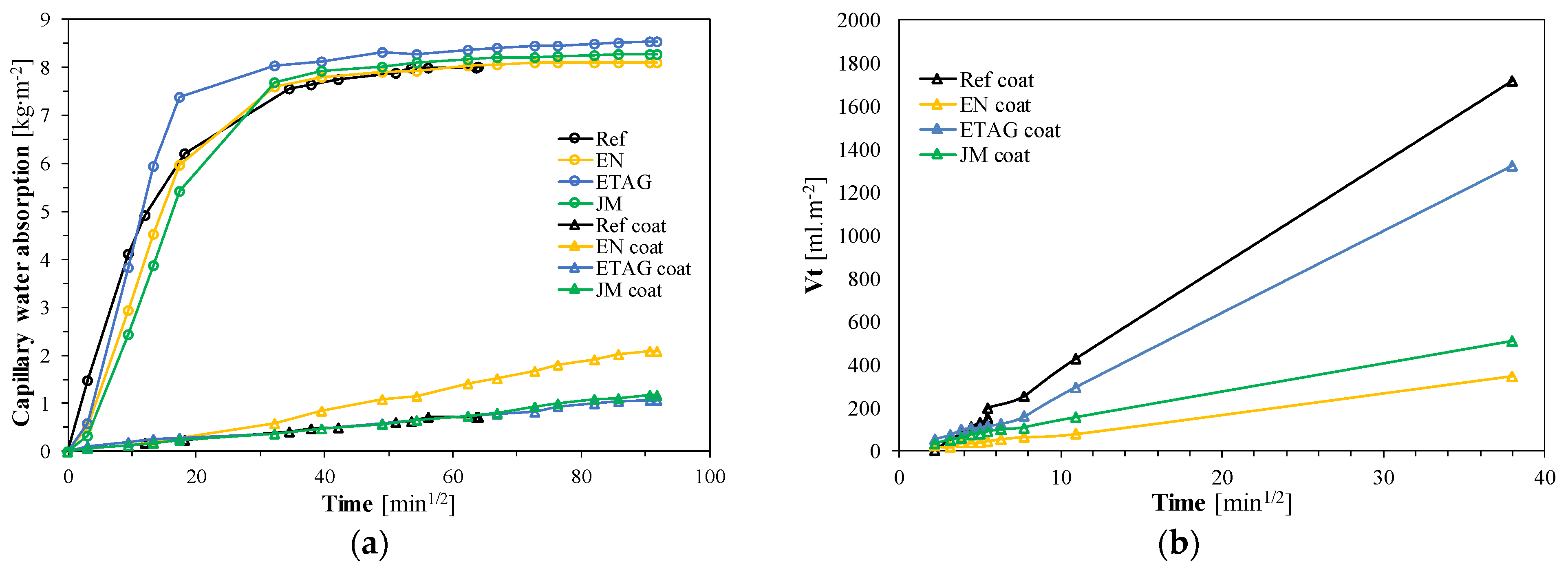
| Method | BD ± SD [g·cm−3] | Ed; ν [MPa] | ft ± SD [MPa] | fc ± SD [MPa] | Cuncoated ± SD [kg∙m−2∙min−1/2] | Ccoated ± SD [kg∙m−2∙min−1/2] |
|---|---|---|---|---|---|---|
| Ref | 0.178 ± 0.006 | 26.0; 0.23 | 0.070 ± 0.008 | 0.147 ± 0.004 | 0.850 ± 0.030 | 0.020 ± 0.004 |
| EN | 0.165 ± 0.005 | 18.5; 0.30 | 0.042 ± 0.004 | 0.080 ± 0.003 | 0.755 ± 0.247 | 0.030 ± 0.010 |
| ETAG | 0.173 ± 0.009 | 20.5; 0.30 | 0.042 ± 0.014 | 0.105 ± 0.012 | 0.900 ± 0.254 | 0.027 ± 0.012 |
| JM | 0.178 ± 0.009 | 33.7; 0.31 | 0.059 ± 0.007 | 0.117 ± 0.013 | 0.780 ± 0.212 | 0.017 ± 0.012 |
| Method | fu (Substrate) ± SD [MPa] | fu (Render) ± SD [MPa] | ϕ ± SD [mm] | Vt (1 h) ± SD [ml.m−2] | Vt (24 h) ± SD [ml.m−2] |
|---|---|---|---|---|---|
| Ref | 0.057 ± 0.006 | 0.063 ± 0.006 | 23.29 ± 1.805 | 254.65 ± 3.473 | 1716.52 ± 0.651 |
| EN | 0.130 ± 0.020 | 0.130 ± 0.017 | 30.82 ± 6.244 | 66.02 ± 0.136 | 348.96 ± 0.046 |
| ETAG | 0.087 ± 0.075 | 0.160 ± 0.082 | 30.06 ± 6.041 | 160.33 ± 0.953 | 1322.75 ± 0.021 |
| JM | 0.040 ± 0.022 | 0.070 ± 0.010 | 22.87 ± 1.577 | 108.46 ± 0.545 | 509.30 ± 0.097 |
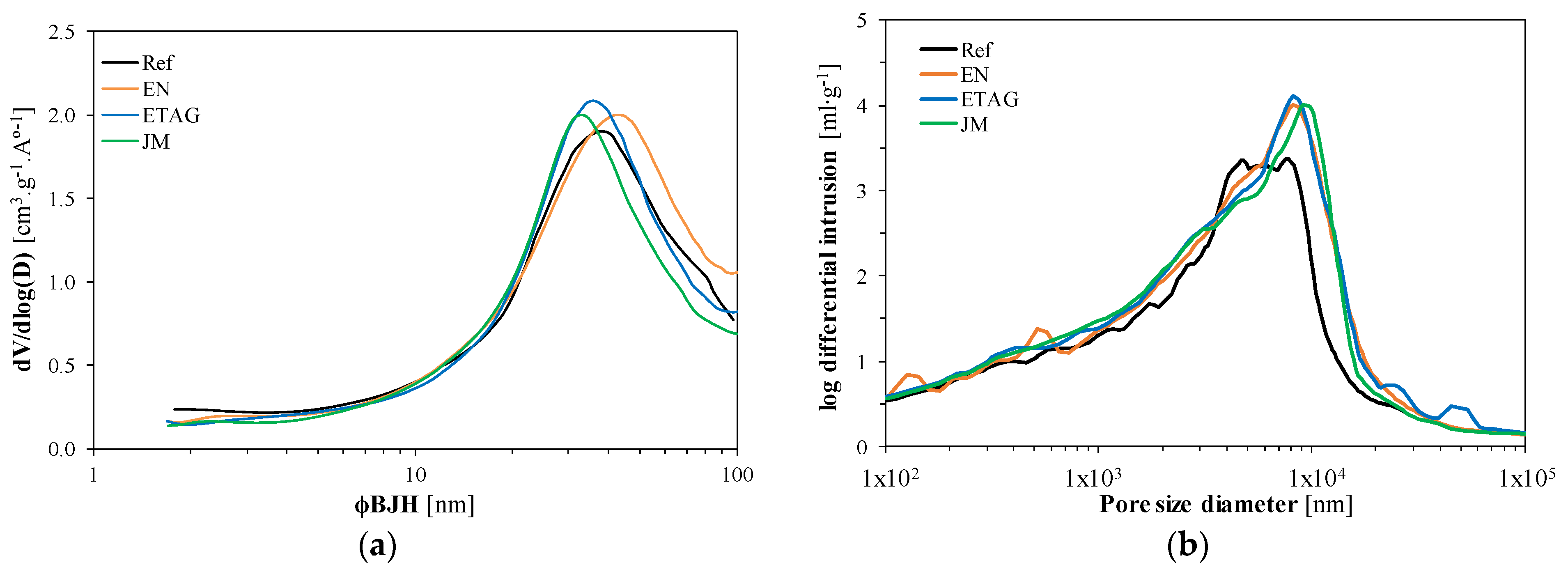
| Method | BET | MIP | |||||||
|---|---|---|---|---|---|---|---|---|---|
| m [g] | S [m2∙cm−1] | CBET | VP [cm3∙g−1] | ΦBJH [nm] | CA [Degree] | m [g] | Total Pore Area [m2∙g−1] | ε [%] | |
| Reference | 0.5351 | 281 | 21 | 1.24 | 16.17 | 140 | 0.1833 | 61.6 | 83.6 |
| EN | 0.2259 | 270 | 22 | 1.25 | 16.02 | 140 | 0.1665 | 68.8 | 81.5 |
| ETAG | 0.2916 | 264 | 22 | 1.21 | 15.97 | 140 | 0.1586 | 67.7 | 85.7 |
| JM | 0.2051 | 252 | 22 | 1.20 | 16.18 | 140 | 0.1640 | 63.2 | 86.2 |
Publisher’s Note: MDPI stays neutral with regard to jurisdictional claims in published maps and institutional affiliations. |
© 2021 by the authors. Licensee MDPI, Basel, Switzerland. This article is an open access article distributed under the terms and conditions of the Creative Commons Attribution (CC BY) license (https://creativecommons.org/licenses/by/4.0/).
Share and Cite
Maia, J.; Pedroso, M.; Ramos, N.M.M.; Flores-Colen, I.; Pereira, P.F.; Silva, L. Durability of a New Thermal Aerogel-Based Rendering System under Distinct Accelerated Aging Conditions. Materials 2021, 14, 5413. https://doi.org/10.3390/ma14185413
Maia J, Pedroso M, Ramos NMM, Flores-Colen I, Pereira PF, Silva L. Durability of a New Thermal Aerogel-Based Rendering System under Distinct Accelerated Aging Conditions. Materials. 2021; 14(18):5413. https://doi.org/10.3390/ma14185413
Chicago/Turabian StyleMaia, Joana, Marco Pedroso, Nuno M. M. Ramos, Inês Flores-Colen, Pedro F. Pereira, and Luís Silva. 2021. "Durability of a New Thermal Aerogel-Based Rendering System under Distinct Accelerated Aging Conditions" Materials 14, no. 18: 5413. https://doi.org/10.3390/ma14185413
APA StyleMaia, J., Pedroso, M., Ramos, N. M. M., Flores-Colen, I., Pereira, P. F., & Silva, L. (2021). Durability of a New Thermal Aerogel-Based Rendering System under Distinct Accelerated Aging Conditions. Materials, 14(18), 5413. https://doi.org/10.3390/ma14185413