
Material Behavior and Fatigue Assessment of Old Steel Bridges of the Spanish Conventional Rail Network

 ,
,  , and
, and
Abstract
:1. Introduction
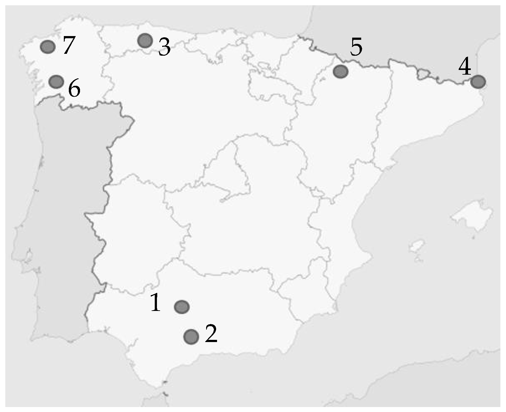
1.1. Description and Background: The Bridges of the Rail Network under Study
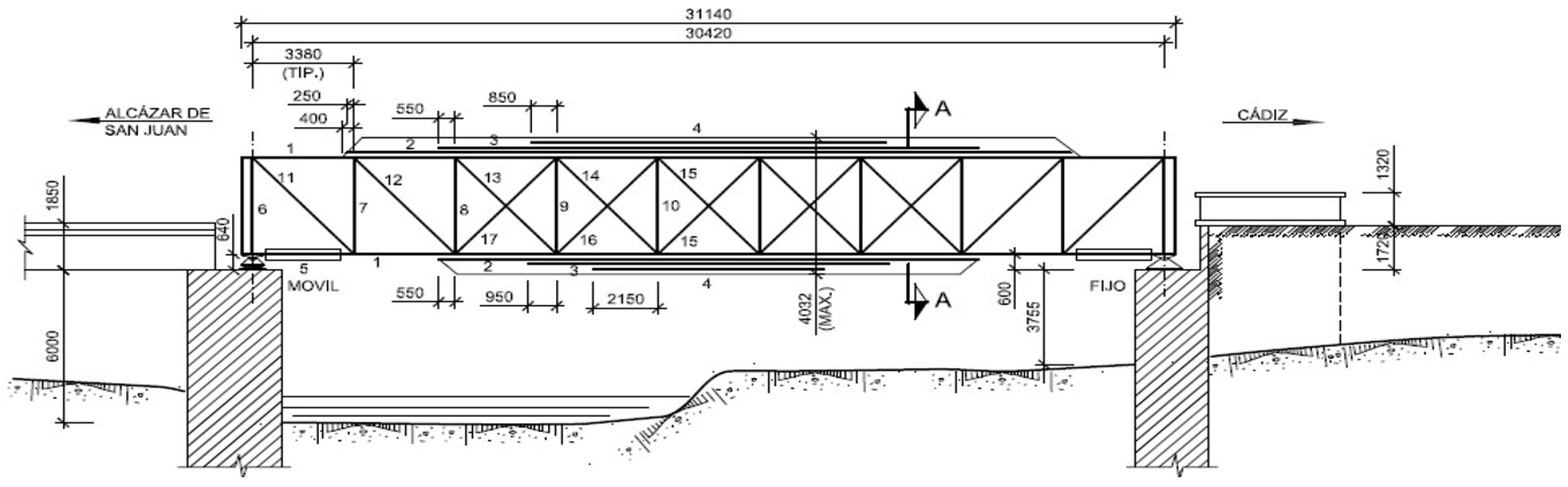
1.2. Description: Bridge “Arroyo Corbones” (Corbones’ River)
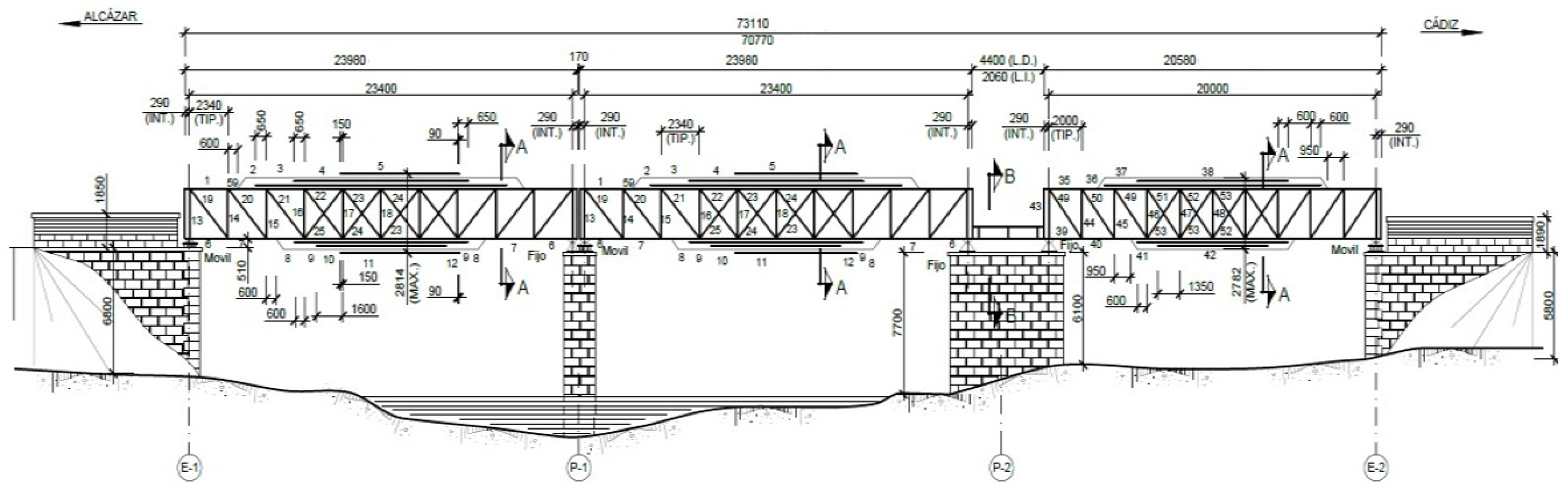
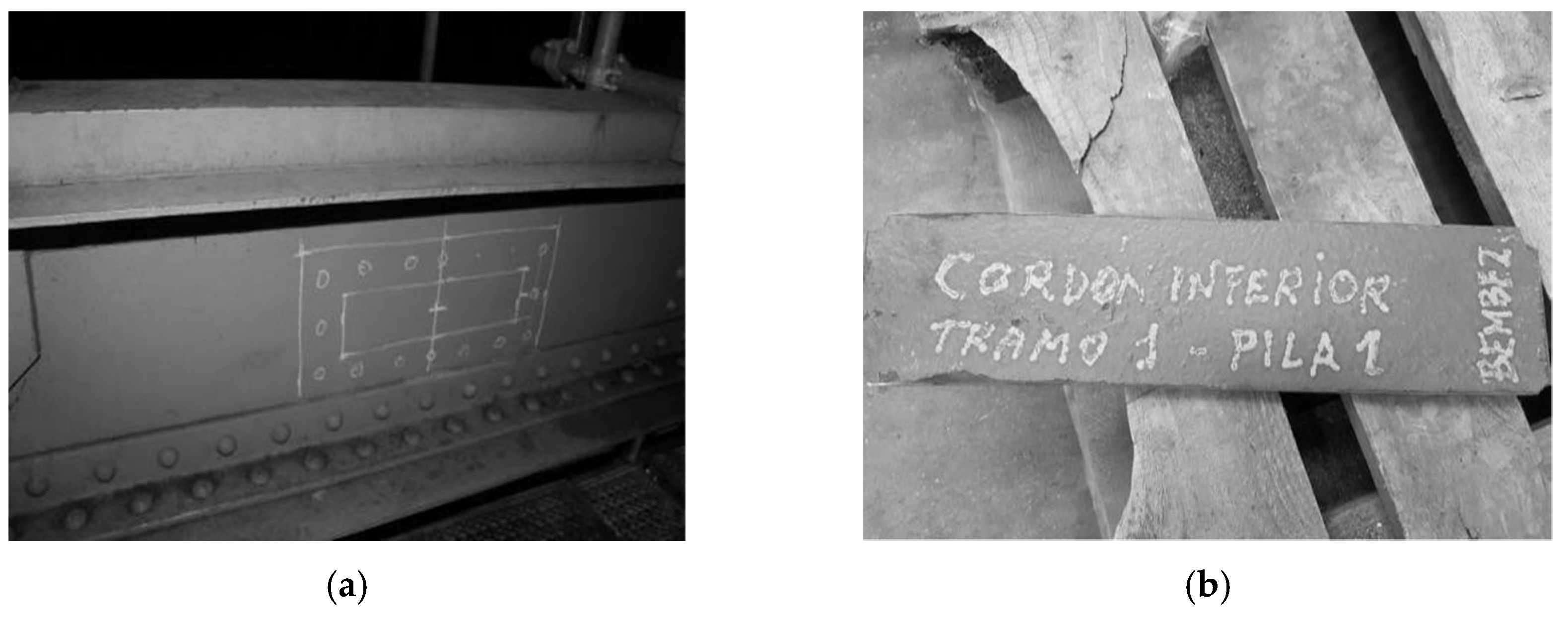
1.3. Description: Bridge “Bembézar”
1.4. Initial Calculation
1.5. Fatigue Live Estimation
2. Materials and Methods
2.1. Sampling
2.2. Experimental Design and Testing
3. Results
3.1. Preliminary Properties Characterization
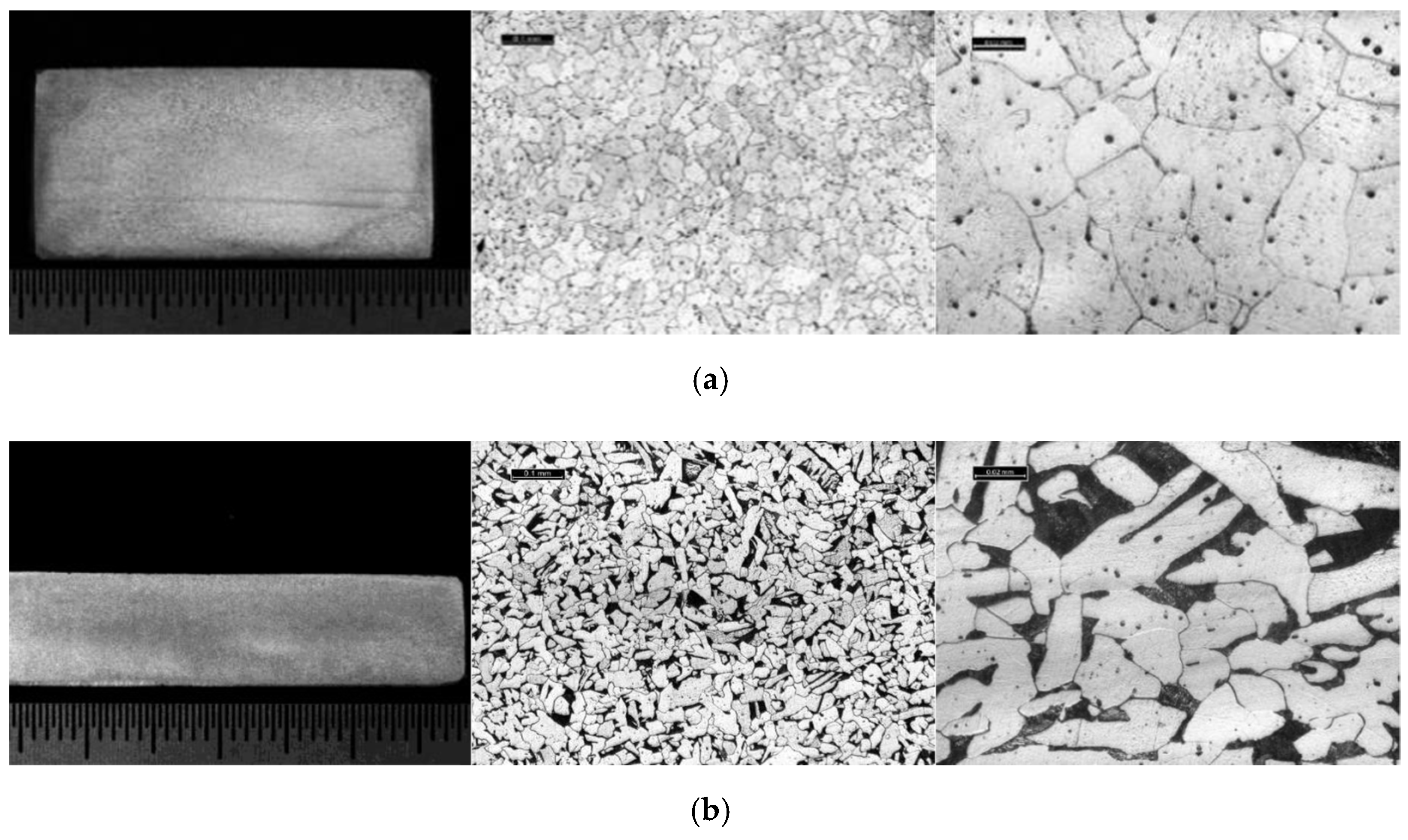
3.2. Microstructure
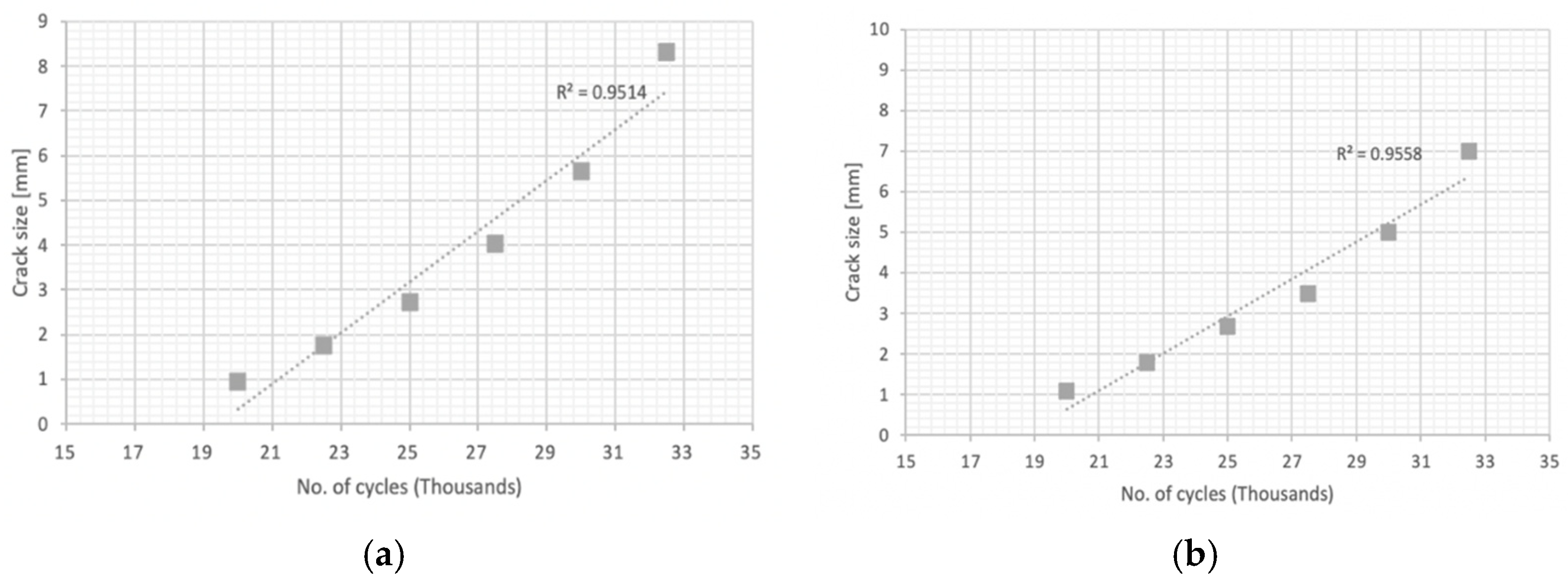
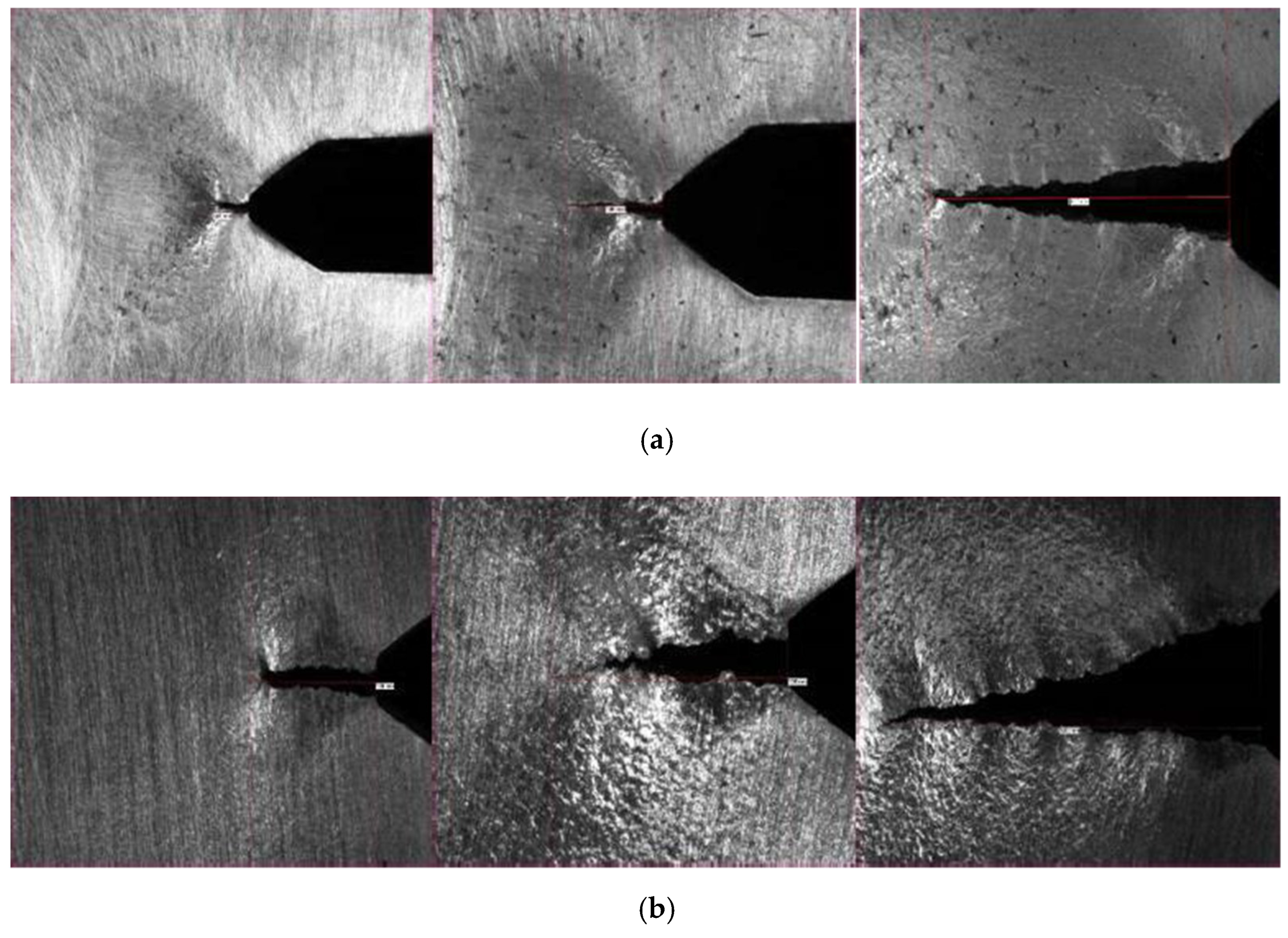
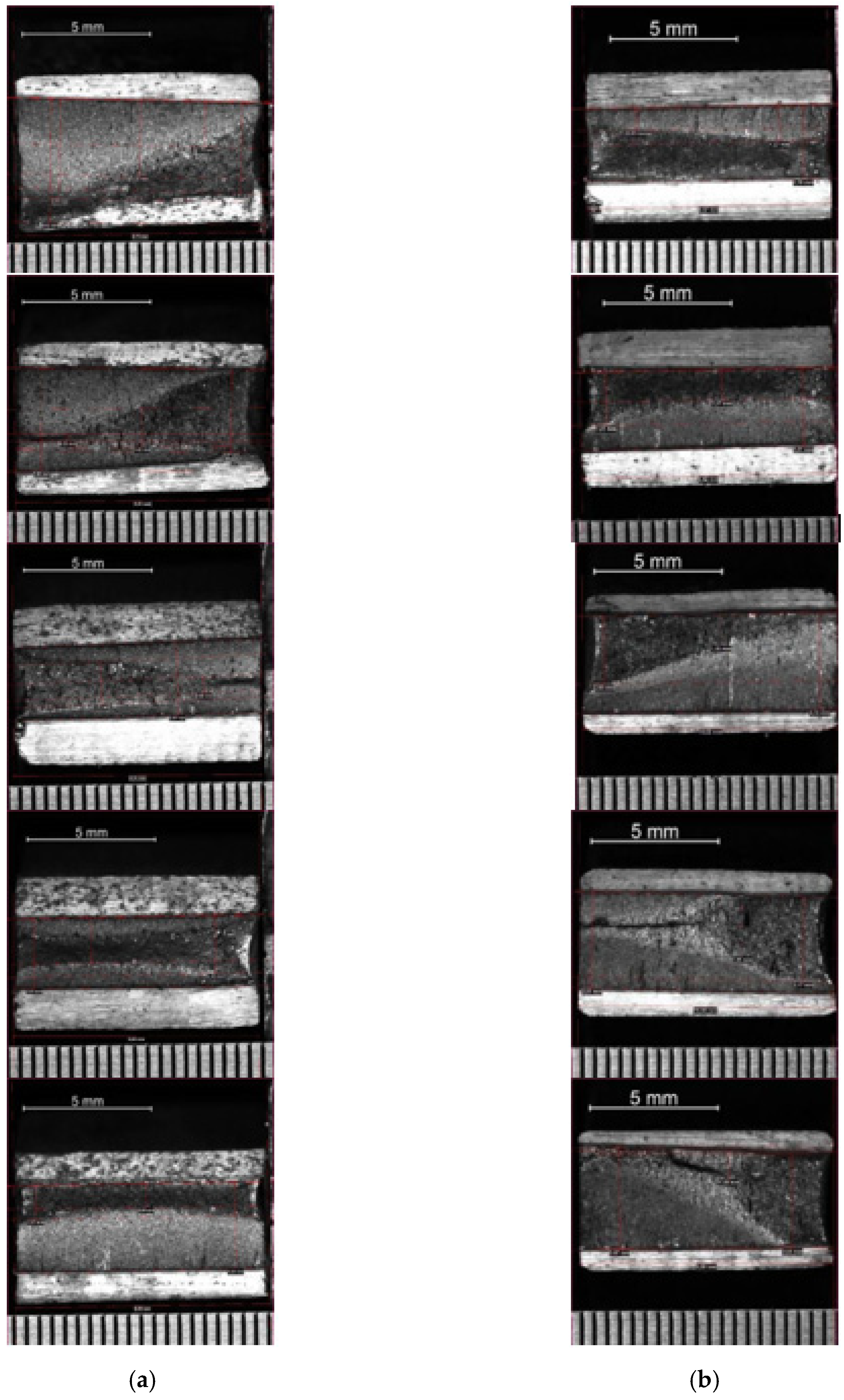
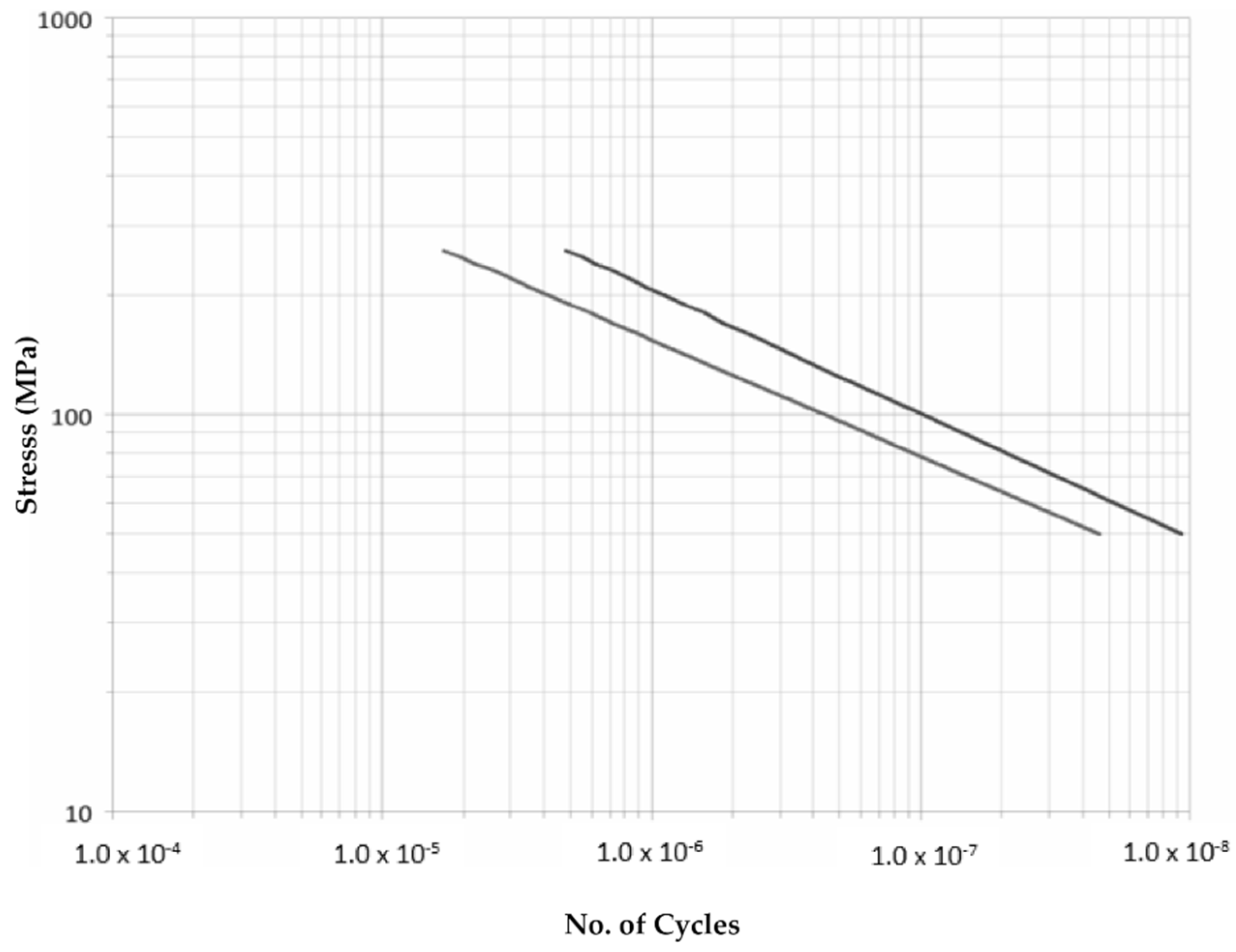
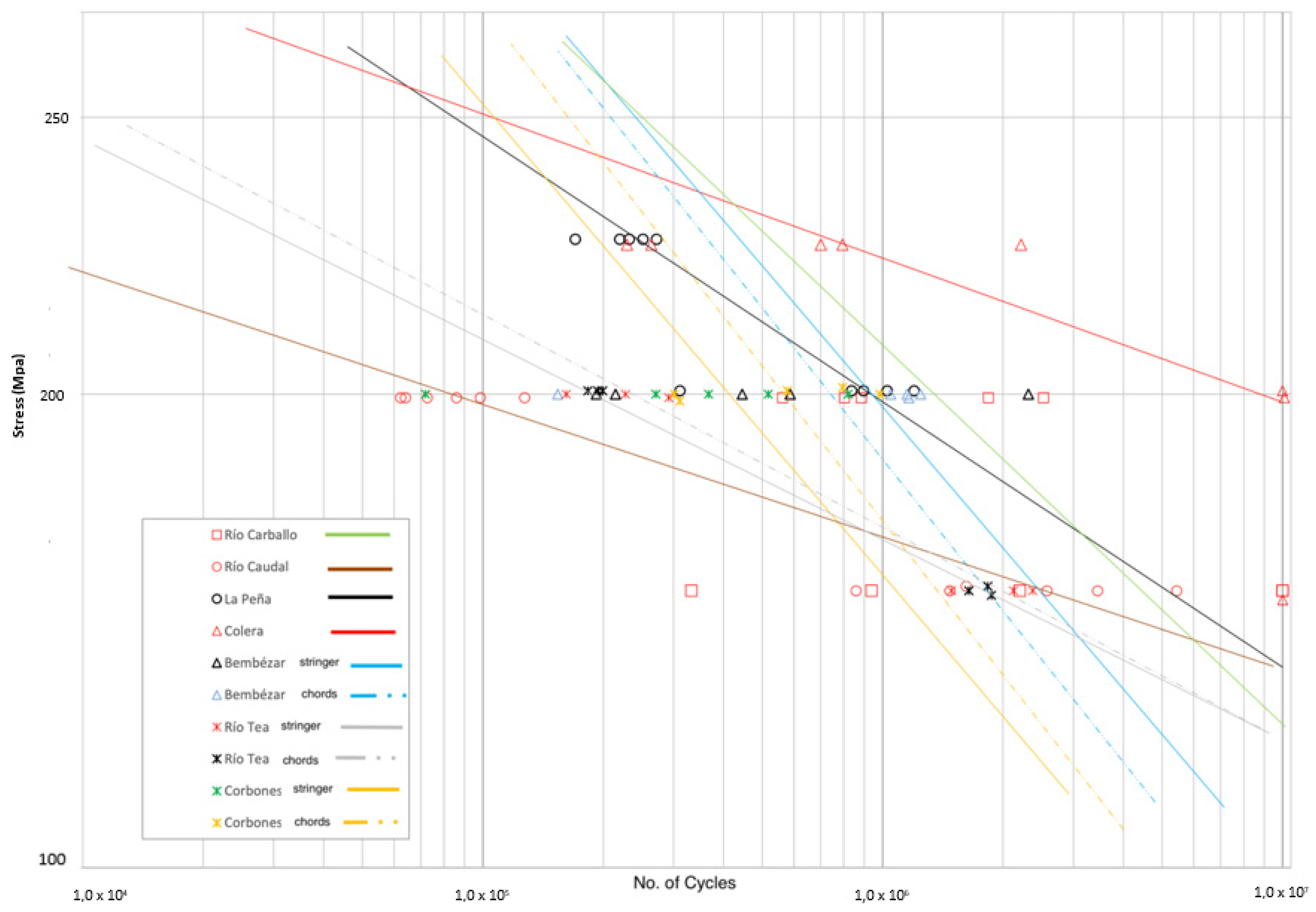
3.3. Fatigue
4. Discussion
Whole Sample Selection Results
5. Conclusions
- In this context, the materials used in the metal bridges were puddled iron until the end of the 19th century, and steel in its different qualities from the end of the 19th century (exclusive steel during the 20th century).
- The evolution in the material resulted in greater control of the manufacturing processes, which allows less dispersion of results, and a precise adjustment to the requirements imposed by the regulations in place (“Instructions for drafting metal bridges projects from 1902 and 1925”).
- It was found that, in some cases, there was a reduction in the mechanical properties of the manufactured material, and as the result of the product was controlled with greater precision (that is to say, more modern steel).
- In all samples without a notch, for the initial loads used, no crack was generated after 107 cycles, so it was estimated to be below the natural endurance limit of the material. Therefore, it was insensitive to fatigue failure unless it has some initial imperfection that triggered the appearance of the crack, after which the crack spread. Under these conditions, new notched specimens were subjected to load cycles of amplitudes of 150 MPa, 200 MPa, and 250 MPa, depending on the elastic limit deduced in the corresponding tests and line with the load estimations obtained from the design structural calculations.
- In all cases, higher results were obtained when the amplitude of the stresses on the fatigue tests remained 100 MPa below the elastic. The next step, 50 MPa below the elastic limit, led to a significant decrease in the number of cycles until fracture (a reduction even higher than predicted with Paris’ law). These results highlight the importance of maintaining this margin of 100 MPa, a margin that was very present in the design codes of 1902 and 1925 where, with an elastic limit requirement of 220 MPa and 250 MPa respectively, the tensions in the pieces were limited to 100–110 MPa and 140 MPa.
- Puddled iron material, despite its low ductility, which is an intrinsic drawback of the material, did not present worse fatigue behavior: quite the contrary, although the tendency to present lamination defects that result in the appearance of relatively premature breaks should be noted.
- At least among the tested bridges, the best performance was observed in bridges from 1910–1920, with those after 1925 showing moderate or even poor performance, not only in terms of fatigue but also in terms of other mechanical parameters. In return, the low values obtained in these bridges presented a much lower dispersion.
- The presence of phosphorus and sulfur impurities did not result in a decrease in the performance of the fatigue parts.
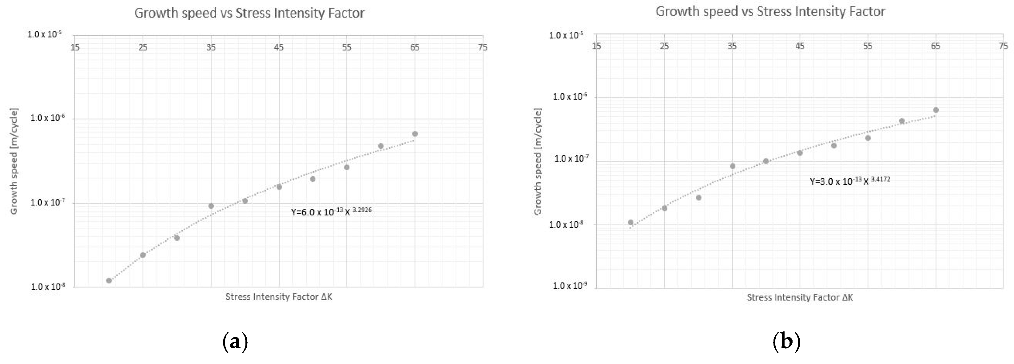
- Finally, and concerning the propagation speed of the crack, conclusions similar to those of the number of cycles were observed, with a great dispersion of results.
Author Contributions
Funding
Institutional Review Board Statement
Informed Consent Statement
Data Availability Statement
Acknowledgments
Conflicts of Interest
References
- Marques, F.; Moutinho, C.; Magalhães, F.; Caetano, E.; Cunha, Á. Analysis of dynamic and fatigue effects in an old metallic riveted bridge. J. Constr. Steel Res. 2014, 99, 85–101. [Google Scholar] [CrossRef] [Green Version]
- American Society of Civil Engineers (ASCE). Committee on fatigue and fracture reliability of the committee on structural safety and reliability of the structural division, fatigue reliability: 1–4. J. Struct. Eng. ASCE 1982, 108, 3–88. [Google Scholar]
- Fisher, J.W. Fatigue and Fracture in Steel Bridges: Case Studies; John Wiley: Hoboken, NJ, USA, 1984. [Google Scholar]
- Fisher, J.W.; Roy, S. Fatigue of steel infrastructure. In Proceedings of the Bridge Maintenance, Safety Management, Health Monitoring and Informatics IABMAS08 Conference, Seoul, Korea, 13–17 July 2008. [Google Scholar]
- Kohout, J.; Vechet, S. A new function for fatigue curves characterization and its multiple merits. Int. J. Fatigue 2001, 23, 175–183. [Google Scholar] [CrossRef]
- Weibull, W. Fatigue Testing and Analysis of Results: Published for and on Behalf of Advisory Group for Aeronautical Research and Development; North Atlantic Treaty Organisation, Pergamon Press: New York, NY, USA, 1961. [Google Scholar]
- Barbosa, J.F.; Correia, J.A.F.D.O.; Montenegro, P.A.; Júnior, R.C.S.F.; Lesiuk, G.; De Jesus, A.M.; Calçada, R.A. A comparison between S-N Logistic and Kohout-Věchet formulations applied to the fatigue data of old metallic bridges materials. Frat. Integrità Strutt. 2019, 13, 400–410. [Google Scholar] [CrossRef]
- de Jesus, A.M.; da Silva, A.L.; Figueiredo, M.; Correia, J.A.F.D.O.; Ribeiro, A.; Fernandes, A. Strain-life and crack propagation fatigue data from several Portuguese old metallic riveted bridges. Eng. Fail. Anal. 2011, 18, 148–163. [Google Scholar] [CrossRef]
- Chaminda, S.S.; Ohga, M.; Dissanayake, R.; Taniwaki, K. Different approaches for remaining fatigue life estimation of critical members in railway bridges. Steel Struct. 2007, 7, 263–276. [Google Scholar]
- Kajolli, R. A New Approach for Estimating Fatigue Life in Offshore Steel Structures. Master’s Thesis, University of Stavanger, Stavanger, Norway, 2013. [Google Scholar]
- WP4 Participants. Guideline for Load and Resistance Assessment of Existing European Railway Bridges—Advices on the Use of Advanced Methods, SB-LRA, Sixth Framework Programme; European Commission: Goteborg, Sweden, 2006. [Google Scholar]
- European Commission 5th Framework Programme (EU FP5). State of the Art Report on Assessment of Structures in Selected EEA and CE Countries; European Commission: Goteborg, Sweden, 2005; Available online: https://trimis.ec.europa.eu/sites/default/files/project/documents/20100310_134040_3529_Samaris_Final_Summary_Report.pdf (accessed on 5 September 2021).
- European Commission 6th Framework Programme (EU FP6). Background Document D3.4: Condition Assessment and Inspection of Steel Railway Bridges, including Stress Measurements in Riveted, Bolted and Welded Structures. SB3.4, Sustainable Bridges; European Commission: Goteborg, Sweden, 2007. [Google Scholar]
- European Commission 6th Framework Programme (EU FP6). Background Document D4.3: Loads and Dynamic Effects. SB4.3, Sustainable Bridge; European Commission: Goteborg, Sweden, 2007. [Google Scholar]
- Ayilara, A.Q.; Liew, M.S.; Ayilara, A.Q.; Wee, T. Need for Fatigue Assessment of Steel Bridges. 2015. Available online: https://www.researchgate.net/publication/305950405 (accessed on 5 September 2021).
- Caglayan, B.; Ozakgul, K.; Tezer, O. Fatigue life evaluation of a through-girder steel railway bridge. Eng. Fail. Anal. 2009, 16, 765–774. [Google Scholar] [CrossRef]
- Crémona, C.; Eichler, B.; Johansson, B.; Larsson, T. Improved Assessment Methods for Static and Fatigue Resistance of Old Metallic Railway Bridges. J. Bridg. Eng. 2013, 18, 1164–1173. [Google Scholar] [CrossRef]
- Ermopoulos, J.; Spyrakos, C.C. Validated analysis and strengthening of a 19th century railway bridge. Eng. Struct. 2006, 28, 783–792. [Google Scholar] [CrossRef]
- Spyrakos, C.C.; Raftoyiannis, I.G.; Ermopoulos, J.C. Condition assessment and retrofit of a historic steel-truss railway bridge. J. Constr. Steel Res. 2004, 60, 1213–1225. [Google Scholar] [CrossRef]
- Wang, C.-S.; Zhai, M.-S.; Duan, L.; Wang, Y.-Z. Cold Reinforcement and Evaluation of Steel Bridges with Fatigue Cracks. J. Bridg. Eng. 2018, 23, 04018014. [Google Scholar] [CrossRef]
- Wichtowski, B.; Woźniak, Z. Właściwości normalizowanej stali zlewnej mostu kolejowego po 75 latach eksploatacji (in Po-lish)/Properties of normalized cast steel of the railway bridge after 75 years of exploitation. Przegląd Spaw. Weld. Technol. Rev. 2015, 87, 110–114. [Google Scholar]
- European Commission 6th Framework Programme (EU FP6). Background Document D4.6: Improved Assessment Methods for Static and Fatigue Resistance of Old Steel Railway Bridges. SB4.6, Sustainable Bridges; European Commission: Goteborg, Sweden, 2007. [Google Scholar]
- Krejsa, M.; Koubova, L.; Flodr, J.; Protivinsky, J.; Nguyen, Q.T. Probabilistic prediction of fatigue damage based on linear fracture mechanics. Frat. Integrità Strutt. 2016, 11, 143–159. [Google Scholar] [CrossRef] [Green Version]
- Gazeta de Madrid. Instruction for the Drafting Projects of Metallic Sections, 1925 (Original in Spanish): Normativa de Carreteras, Instrucción Para la Redacción de Proyectos en Tramos Metálicos del 24.10.1925, No. 297. Available online: https://normativadecarreteras.com/listing/instruccion-para-la-redaccion-de-proyectos-de-tramos-metalicos-24-10-1925/ (accessed on 14 August 2021).
- Gazeta de Madrid. Instruction for the Drafting of Metallic Bridges Projects, 1902 (Original in Spanish): Instrucción Para Redactar Los Proyectos de Puentes Metálicos, 05-06-1902. No. 157. Available online: https://normativadecarreteras.com/listing/instruccion-para-redactar-los-proyectos-de-puentes-metalicos-05-06-1902/ (accessed on 14 August 2021).
- Vélez Álvaro, P.; Sánchez, A.B.; Fernández, M.M.; Muñiz, Z.F.; Vélez, P.; Fernández, M.; Muñiz, F. Multivariate Analysis to Relate CTOD Values with Material Properties in Steel Welded Joints for the Offshore Wind Power Industry. Energies 2019, 12, 4001. [Google Scholar] [CrossRef] [Green Version]
- Cheng, T.C.; Yu, C.; Yang, T.C.; Huang, C.Y.; Lin, H.C.; Shiue, R.K. Microstructure and Impact Toughness of Offshore Steel. Arch. Metall. 2018, 63, 167–172. [Google Scholar]
- Castelluccio, G.M.; McDowell, D.L. Microstructure-sensitive small fatigue crack growth assessment: Effect of strain ratio, multiaxial strain state, and geometric discontinuities. Int. J. Fatigue 2016, 82, 521–529. [Google Scholar] [CrossRef]
- ASM International. ASTM E647-08: Standard test method for measurement of fatigue crack growth rates. In Annual Book of ASTM Standards; ASM International: West Conshohocken, PA, USA, 2004; Volume 03.01. [Google Scholar]
- Gutiérrez, S.F.; González, J. Comportamiento en Fatiga de Puentes Metálicos Antiguos de Ferrocarril; Revista de Obras Públicas: Madrid, Spain, 1992. [Google Scholar]
- BS EN 10025:2019: Part 2: Technical Delivery Conditions for Non-Alloy Structural Steels; BSI Standards Publication: London, UK, 2019.
- Kowal, M.; Szala, M. Diagnosis of the microstructural and mechanical properties of over century-old steel railway bridge components. Eng. Fail. Anal. 2020, 110, 104447. [Google Scholar] [CrossRef]


| “Arroyo Corbones” | Estimated for 90 Years + 50% |
| Elements of the main chords: | 1.68 million cycles |
| Side members elements: | 55.1 million cycles |
| Joist elements: | 25.9 million cycles |
| “Bembézar” | Estimated for 90 Years + 50% |
| Elements of the main chords: | 1.1 million cycles |
| Side members elements: | 41.2 million cycles |
| Joist elements: | 19.5 million cycles |
| 1st Phase | 2nd Phase | 3rd Phase | 4th Phase |
|---|---|---|---|
| Preliminary Mechanical Tests | Fracture Mechanics | Fatigue (Un-notched) | Fatigue (Double-notched) |
| Macrographic and Micrographic examination according to ASTM E112 (2013). Preparation of the sample according to the guide E3-11. Chemical content of C, Si and S by optical emission spectrometry (SpectroMax Metal Analyzer) Tensile test according to UNE-EN ISO 6892-1: B (Average of three or two tests depending on the sample availability) Toughness measured by Charpy V-notch UNE-EN ISO 148-1 CVN specimens 10 × 10 mm. Temperature of 0 °C. 300 J Pendulum. | Determination of the “m” coefficient Paris Law expressed as: da/dN = C(ΔK)m Pre-cracked (one-side) SE(B) specimens tested with a clip-on extensometer IB-3541-008M-040M-ST-E339 and software according to ASTM E647. Crack growth measured by optical microscopy. Machine: Dynamic tensile machine UFIB-200E-MD5W | Flat-sheet Fatigue Specimen with rectangular cross section as per ASTM E606 (a) Thickness as received (8–10 mm) Machine: Dynamic tensile machine UFIB-200E-MD5W Frequency: 10 Hz R: 0.1 No. of Cycles: 107 | Flat-sheet Fatigue Specimen with rectangular cross section as per ASTM E606 (a) Thickness as received (8–10 mm) Notch: 2 mm deep, 45 degrees and R0.25 mm Machine: Dynamic tensile machine UFIB-200E-MD5W Frequency: 10 Hz R: 0.1 No. of Cycles: To failure |
| Tests performed on the following metal bridges (seven): “Bembézar” (Stringers + Chords) “Corbones” (Stringers + Chords) “Caudal” (Stringers) “Carballo” (Stringers) “La Peña” (Stringers) “Colera” (Stringers) “Tea” (Stringers) | Tests performed on the following metal bridges (two): “Bémbezar” (Stringers + Chords) “Corbones” (Stringers + Chords) | Tests performed on the following metal bridges (seven): “Bembézar” (Stringers + Chords) “Corbones” (Stringers + Chords) “Caudal” (Stringers) “Carballo” (Stringers) “La Peña” (Stringers) “Colera” (Stringers) “Tea” (Stringers) | Tests performed on the following metal bridges (seven): “Bembézar” (Stringers + Chords) “Corbones” (Stringers + Chords) “Caudal” (Stringers) “Carballo” (Stringers) “La Peña” (Stringers) “Colera” (Stringers) “Tea” (Stringers) |
| Puddle Iron | Steel (1905–1910) | Steel (1917–1920) | Steel (>1925) | |||||||
|---|---|---|---|---|---|---|---|---|---|---|
| Metallic Bridge: | “Carballo” | “Caudal” | “La Peña” | “Colera” | “Bémbezar” Stringers | “Bémbezar” Chords | “Tea” Stringers | “Tea” Chords | “Corbones” Stringers | “Corbones” Chords |
| YS (0.2%) (MPa) | 312.8 (297–324) | 283.4 (272–289) | 329.2 (321–342) | 313.2 (271–351) | 269.3 (261–277) | 307 (300–314) | 253.6 (242–266) | - | 293 (289–299) | 255 (254–356) |
| UTS (MPa) | 367.4 (355–375) | 381.2 (375–388) | 418 (416–421) | 379 (358–400) | 332 (331–333) | 367 (366–368) | 405 (337–463) | - | 409.3 (404–418) | 382.5 (380–385) |
| Elongation (%) | 9 (8–10) | 35 (34–36) | 32 (30–33) | 35 (30–42) | 39 (37–41) | 32 (31–32) | 30 (26–32) | - | 34 (33–34) | 35 (35) |
| C[w/w%] | 0.016 | 0.068 | 0.095 | 0.049 | 0.029 | 0.054 | 0.0252 | 0.074 | 0.02 | 0.012 |
| P[w/w%] | 0.12 | 0.065 | 0.084 | 0.123 | 0.036 | 0.054 | 0.012 | 0.014 | 0.006 | 0.004 |
| S[w/w%] | 0.036 | 0.074 | 0.027 | 0.12 | 0.039 | 0.084 | 0.06 | 0.03 | 0.021 | 0.018 |
| Impact Test (J) | 6 (3–10) | 71 (56–84) | 18 (15–21) | 6 (4–12) | 7 (6–10) | 9 (8–9) | 12 (7–19) | - | 14 (12–17) | 8 (7–9) |
| No. Cycles (200 MPa, 10 Hz, R: 0.1) | |||
|---|---|---|---|
| Sample 1 Stringers: | 820,006 | Sample 1 Chords: | 301,452 |
| Sample 2 Stringers: | 71,909 | Sample 2 Chords: | 984,618 |
| Sample 3 Stringers: | 517,416 | Sample 3 Chords: | 577,975 |
| Sample 4 Stringers: | 367,332 | Sample 4 Chords: | 794,206 |
| Sample 5 Stringers: | 271,047 | Sample 5 Chords: | 311,040 |
| Corbones-Stringers- | Corbones-Main Chords- |
|---|---|
| Avg. growth per cycle: 0.00000373 mm | Avg. growth per cycle: 1.3474 × 10⁻⁶ mm |
| Cycles per mm of growth: 268,356 | Cycles per mm of growth: 742,127 |
| No. Cycles (200 MPa, 10 Hz, R: 0.1) | |||
|---|---|---|---|
| Sample 1 Stringers: | 2,315,105 | Sample 1 Chords: | 153,871 |
| Sample 2 Stringers: | 192,268 | Sample 2 Chords: | 1,151,432 |
| Sample 3 Stringers: | 587,475 | Sample 3 Chords: | 1,046,938 |
| Sample 4 Stringers: | 445,612 | Sample 4 Chords: | 1,163,466 |
| Sample 5 Stringers: | 214,773 | Sample 5 Chords: | 1,244,549 |
| Bembézar-Stringers- | Bembézar-Main Chords- |
|---|---|
| Avg. growth per cycle: 0.00000416 mm | Avg. growth per cycle: 0.000003 mm |
| Cycles per mm of growth: 268,356 | Cycles per mm of growth: 330,037 |
| Puddle Iron | Steel (1905–1910) | Steel (1917–1920) | Steel (>1925) | |||||||
|---|---|---|---|---|---|---|---|---|---|---|
| Metallic Bridge: | “Carballo” | “Caudal” | “La Peña” | “Colera” | “Bémbezar” Stringers | “Bémbezar” Chords | “Tea” Stringers | “Tea” Chords | “Corbones” Stringers | “Corbones” Chords |
| YS (0.2%) (MPa) | 312.8 (297–324) | 283.4 (272–289) | 329.2 (321–342) | 313.2 (271–351) | 269.3 (261–277) | 307 (300–314) | 253.6 (242–266) | - | 293 (289–299) | 255 (254–356) |
| UTS (MPa) | 367.4 (355–375) | 381.2 (375–388) | 418 (416–421) | 379 (358–400) | 332 (331–333) | 367 (366–368) | 405 (337–463) | - | 409.3 (404–418) | 382.5 (380–385) |
| Elongation (%) | 9 (8–10) | 35 (34–36) | 32 (30–33) | 35 (30–42) | 39 (37–41) | 32 (31–32) | 30 (26–32) | - | 34 (33–34) | 35 (35) |
| C[w/w%] | 0.016 | 0.068 | 0.095 | 0.049 | 0.029 | 0.054 | 0.0252 | 0.074 | 0.02 | 0.012 |
| P[w/w%] | 0.12 | 0.065 | 0.084 | 0.123 | 0.036 | 0.054 | 0.012 | 0.014 | 0.006 | 0.004 |
| S[w/w%] | 0.036 | 0.074 | 0.027 | 0.12 | 0.039 | 0.084 | 0.06 | 0.03 | 0.021 | 0.018 |
| Impact Test (J) | 6 (3–10) | 71 (56–84) | 18 (15–21) | 6 (4–12) | 7 (6–10) | 9 (8–9) | 12 (7–19) | - | 14 (12–17) | 8 (7–9) |
| Fatigue 150 MPa (Cycles/mm) | - | 979,556 | - | - | - | - | 541,645 | 653,337 | - | - |
| Fatigue 200 MPa (Cycles/mm) | 628,393 | 34,934 | 157,747 | - | 268,356 | 74,227 | 60,807 | 57,881 | 330,037 | 240,790 |
| Fatigue 250 MPa (Cycles/mm) | - | - | 191,156 | 186,534 | - | - | - | - | - | - |
Publisher’s Note: MDPI stays neutral with regard to jurisdictional claims in published maps and institutional affiliations. |
© 2021 by the authors. Licensee MDPI, Basel, Switzerland. This article is an open access article distributed under the terms and conditions of the Creative Commons Attribution (CC BY) license (https://creativecommons.org/licenses/by/4.0/).
Share and Cite
Presno Vélez, Á.; Bernardo Sánchez, A.; Bruna, O.A.; Abella, D.M.; de Prado, L.Á.; Fernández, M.M. Material Behavior and Fatigue Assessment of Old Steel Bridges of the Spanish Conventional Rail Network. Materials 2021, 14, 5275. https://doi.org/10.3390/ma14185275
Presno Vélez Á, Bernardo Sánchez A, Bruna OA, Abella DM, de Prado LÁ, Fernández MM. Material Behavior and Fatigue Assessment of Old Steel Bridges of the Spanish Conventional Rail Network. Materials. 2021; 14(18):5275. https://doi.org/10.3390/ma14185275
Chicago/Turabian StylePresno Vélez, Álvaro, Antonio Bernardo Sánchez, Octavio Ariñez Bruna, Diego Madera Abella, Laura Álvarez de Prado, and Marta Menéndez Fernández. 2021. "Material Behavior and Fatigue Assessment of Old Steel Bridges of the Spanish Conventional Rail Network" Materials 14, no. 18: 5275. https://doi.org/10.3390/ma14185275
APA StylePresno Vélez, Á., Bernardo Sánchez, A., Bruna, O. A., Abella, D. M., de Prado, L. Á., & Fernández, M. M. (2021). Material Behavior and Fatigue Assessment of Old Steel Bridges of the Spanish Conventional Rail Network. Materials, 14(18), 5275. https://doi.org/10.3390/ma14185275