1. Introduction
The automotive sector is evolving to a more environmentally friendly methodology. The development in weight reduction and electrification technologies requires substantial changes in material selection and component design [
1]. The introduction of polymers and fiber-reinforced materials allows the reduction of emissions and an increase in vehicle material circularity. Thermoplastics are a leading alternative to improve weight reductions and the overall recyclability of vehicles. Carbon fiber reinforced polymers (CFRP) and glass fiber reinforced polymers (GFRP) have become more diffuse in the industry [
2], due also to innovative methods of using them, such as rapid prototyping [
3] or when machining is a valid alternative to traditional plastic processing for small batch production. For this reason, these materials need to fully abide by the quality standards required in the sector.
The machinability of thermoplastics and composites has been extensively studied to achieve the required geometry, tolerance, and surface finish of automotive components. Analysis of the scientific literature indicates that several aspects have been proven to be vital in the machining of reinforced thermoplastics. Polymers are considered complex materials because of their low thermal diffusivity and thermal dependency on mechanical properties [
4,
5]. The high values of the thermal expansion coefficient make it challenging to produce parts without shape deviation. The viscoelastic behavior offers a technological challenge because of the interaction between the strain rate and temperature. As a result, the viscous deformation strongly influences the overall quality of the machined surfaces. The process conditions should be accurately selected in the regime with no scaling/tearing or brittle cracking [
6]. The machining efficiency is strictly determined by the chemical and thermo-physical properties of the selected polymer and its reinforcement. It is imperative to correlate the machining performances to these materials, evaluating the effect of the process parameters on the surface integrity [
7]. The analysis of cutting forces and surface roughness is crucial to appropriately plan and control the machining operation. The cutting force and surface quality should be investigated as the primary response data to achieve optimal results [
8]. Thus, machining is performed at low speed and low material removal rates to provide high dimensional and surface quality [
9]. Specific polymers present a high impact resistance and suffer deflections, resulting in shape defects in the machined part due to the contact between the cutting tool and the material surface. A reinforced material has a significant impact on tool life due to its abrasive nature [
10]. Regarding fibers, debonding between the matrix and fibers, and delamination during material removal, strongly affect the final surface’s texture [
11].
The review of the scientific literature available on the material grindability of reinforced plastics reveals several essential factors. These materials, characterized by high cutting heat, high fiber hardness, and heterogeneous structure, are challenging to process, are vulnerable to cracking, and produce large quantities of dust. The latter usually induce adhesive wear on the grinding wheel and decrease the material removal rate and processing efficiency [
12]. Moreover, a clean-cut surface without uncut ends is difficult to achieve because the grinding grains cannot sharply cut the fibers [
13]. In the grinding process, a cutting fluid is used to minimize the harmful effects caused by a large amount of heat in the cutting zone. Studying the grinding behavior under different lubricant–coolant techniques is decisive to appraise the surface roughness, grinding force, and specific grinding energy [
14]. An alternative grinding approach involves using small diameter abrasive cutters or grinding points either with plain or contoured profiles, which can be used similarly to end mills when trimming/routing CFRP [
15]. For grinding, the essential values to estimate are the energy partition for mechanical efficiency and the specific energy spent to remove a particular volume of material [
16]. Direct measurement of the temperature distribution is complicated due to the minute contact zone for heat transfer. Alternatively, temperature measurement is more accessible, and these measurements are often used to retrieve the heat flux [
17]. The influence of the grinding heat on the machined surface is also analyzed based on the grinding temperature at the wheel contact area to evaluate the temperature at which glass transition occurs and thermal alteration can result [
18].
The above facts, combined with the described increase in the demand for improving polymer adoption, create a concrete opportunity to research the grindability of reinforced thermoplastics. Grinding of unfilled and glass-fiber reinforced Polyamide 66 (PA66) was carried out, process efficiency was experimentally calculated and monitored, and the main physical variables were determined. In particular, the forces, energy partition, and specific energy of samples produced, starting from conventional methods (extrusion and machining), were experimentally verified under different grinding conditions and with other grinding wheels. The study of the grinding, limited only to polyamide materials, was transferred from the laboratory experience to a practical scale. The novelty of the present work is that the forces, energy partition, and specific energy of polyamide samples produced starting from conventional methods (extrusion and machining) were experimentally verified for the first time under different grinding conditions.
3. Results
Preliminary analyses compared ground and nonground specimens. From rough materials, 60 samples for each material (120 in total) with dimensions of 60 × 30 × 5 mm
3, were realized and their surface quality was characterized before grinding.
Ra and
Rz were measured (
Table 3), testing the surface roughness for normality with the Anderson–Darling technique. Quality control was enforced to decide to accept a part when the print requirements were not consistent with measurements on the surface gages in the local facility. In these cases,
Ra and
Rz were the fastest parameters to be determined. More in-depth analysis should be made offline with the use of focus-variation microscopy [
20]. Compared to the glass-fiber PA66, the unfilled PA66 presented a lower mean value but a higher deviation, and failed to fit a normal distribution, as observed in the
p-value. The deviation was lower for the PA66GF30, and there was no significant departure from normality because the
p-value for
Ra and
Rz was higher than 0.05. The presence of fibers and material elongation at break accounted for this behavior. The presence of fibers generated a rougher surface due to the randomness of their distribution in the matrix. During machining, there was also a certain degree of adhesion between the removed layer of material, tools, and the surface, leading to defects such as fiber pull-out and fiber/matrix debonding, negatively impacting the surface texture. For this reason, the surface quality of PA66GF30 was worse than that of PA66. Alternatively, the lower deviation was explained through the significant difference in the deformation that the materials presented when breaking.
The PA66 deformed at 70% of its original length, compared to 14% for the filled PA66. This property generated more minor chips during manufacturing, less heat accumulation on the cutting zone, and a more reliable process. Less temperature in the contact zone led to more desirable material behavior because the material was glassy and presented a lower degree of viscous deformation below
Tg. Some preliminary experiments suggested three initial cutting depths
ae, repeated three times. A finishing grinding wheel completed the tests to achieve high quality with one grinding pass. As a result, the total number of samples per material was nine.
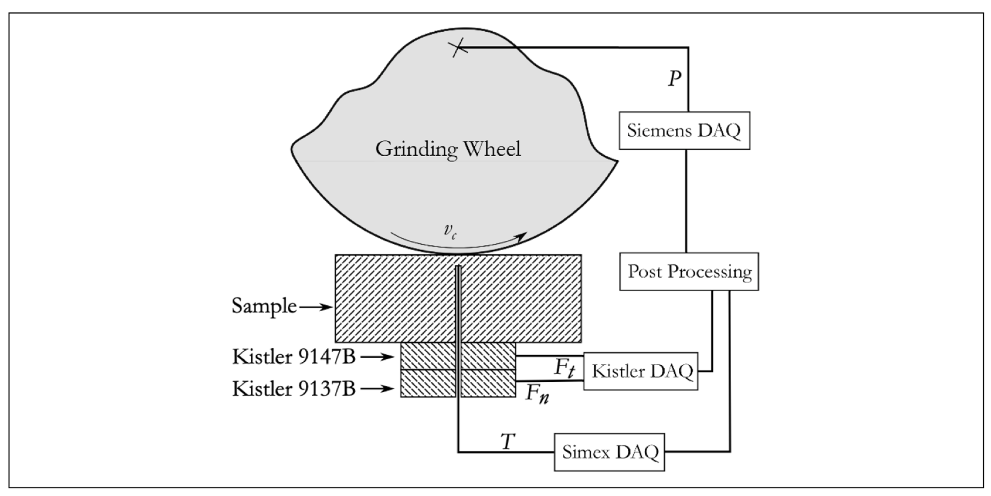
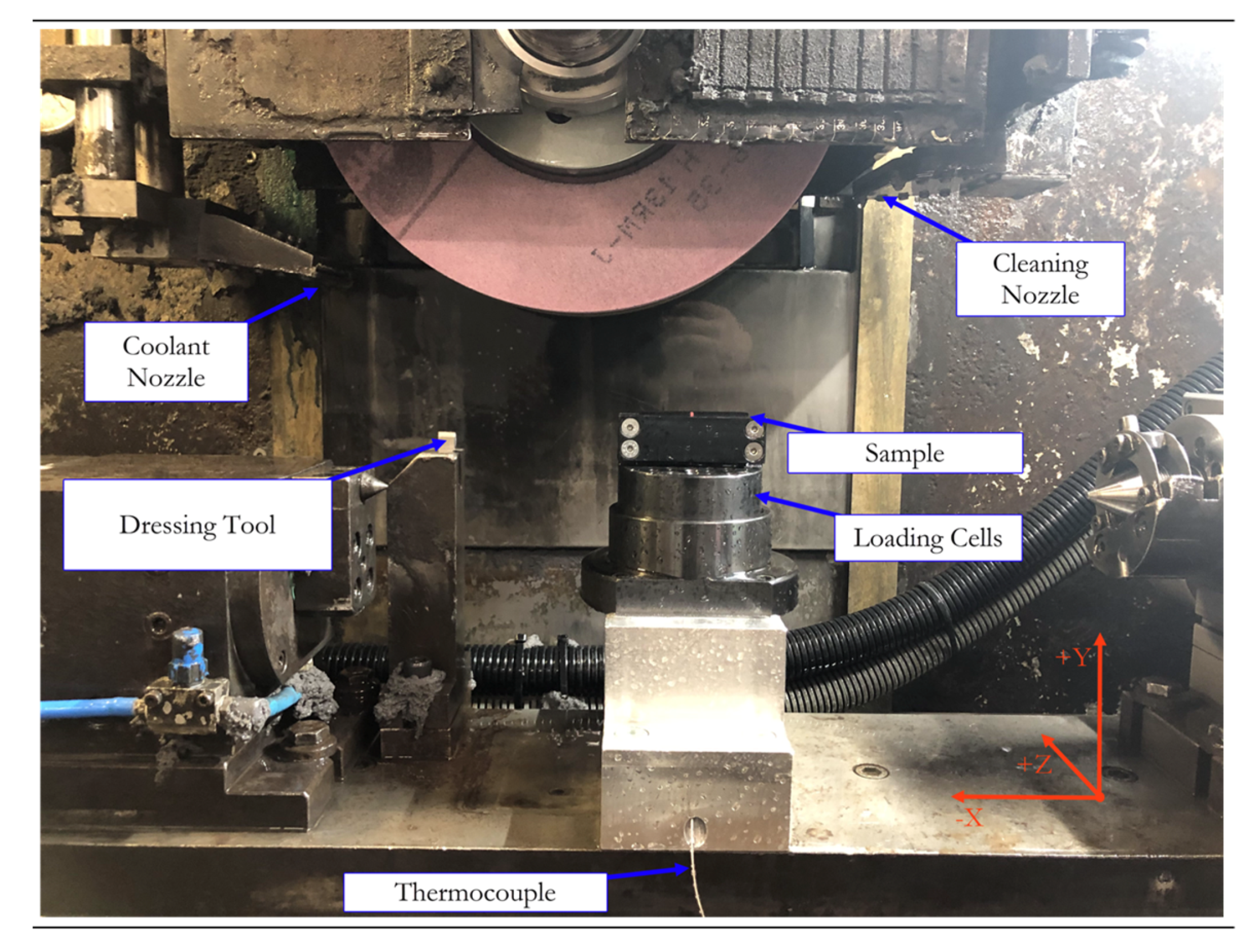
Table 4 reports the dressing and grinding parameters. At the beginning of each test, the grinding wheel was dressed before the data acquisition pass. During dressing, the cutting speed was higher than the normal operating speed to remove all traces of previous experiments. Excessive wear of the grinding wheel resulted if the dressing speed used was tool low. Each leveled sample, starting with the same flatness, avoiding influences from other processes. Due to the different data acquisition channels, the original data were not synchronized, and a post-processing phase fused all the data. The selected grinding parameters for this experiment diverged from those of previous works [
19,
21] due to the sample geometry and sampling limitations. The length of the grinding wheel path for force acquisition was only 60 mm. High infeed speeds would provide insufficient data for the acquisition. This also happens if the workpiece speed is too low. The number of sampling points would be too high for the instrument, and forces may become so low that they would not be sensed by the loading cells.
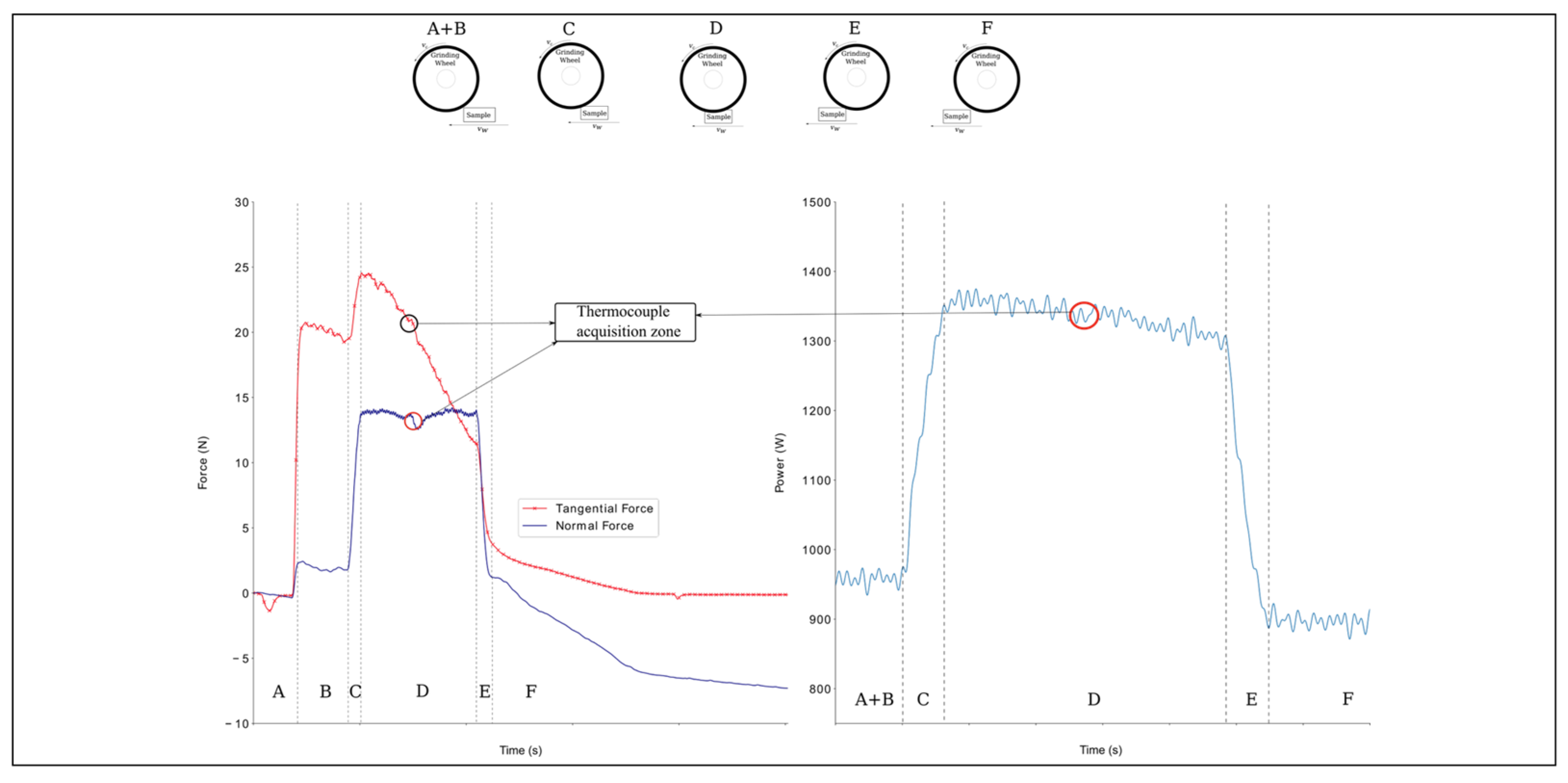
Several phases were identified during acquisition (
Figure 4):
There was no contact between the sample and the tool. There was no contact with the workpiece, and the spindle wheel used minimal power to maintain the imposed cutting speed vc.
The coolant was activated, generating a significant variation in the tangential force and a minor variation in the normal force. The tangential component was more critical because the coolant nozzle pointed directly at a point close to the interaction between the workpiece and the wheel. Up-grinding was performed, and the wheel spin facilitated the entrance of the coolant into the contact zone. The spindle wheel continued to maintain the required cutting speed vc.
The first contact between the tool and specimen caused an increase in both forces. The drive increased power to the spindle to maintain vc. The grinding area was at the maximum level, and the power entered a steady state at a higher power level. The difference between the idle power and this level was the net grinding power responsible for the cut, and was directly linked to the tangential force.
Contact remained stable. The normal force maintained the pressure in the workpiece while the tangential force cut the material. The tangential force decayed with the material removal.
A rapid reduction of both signals appeared. The wheel began to move away from the piece and, because there was no more impediment to spinning, the power decreased.
The process is finished. The normal signal was not able to return to zero because of a spring back compensation due to the compression forces during machining. Grinding was finished, and the power returned to idle.
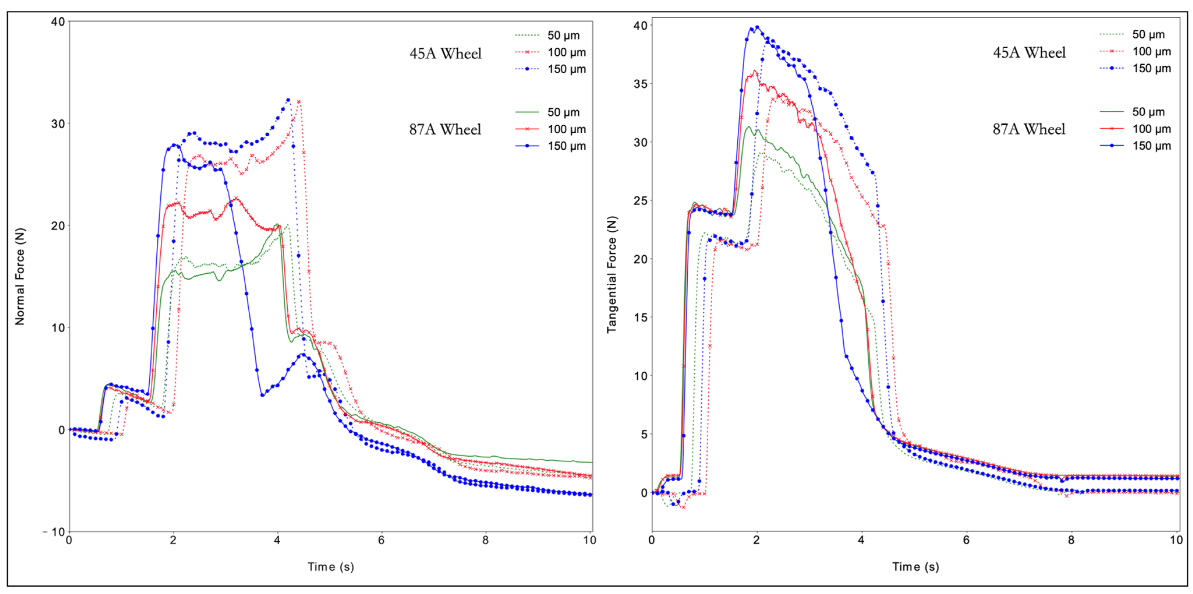
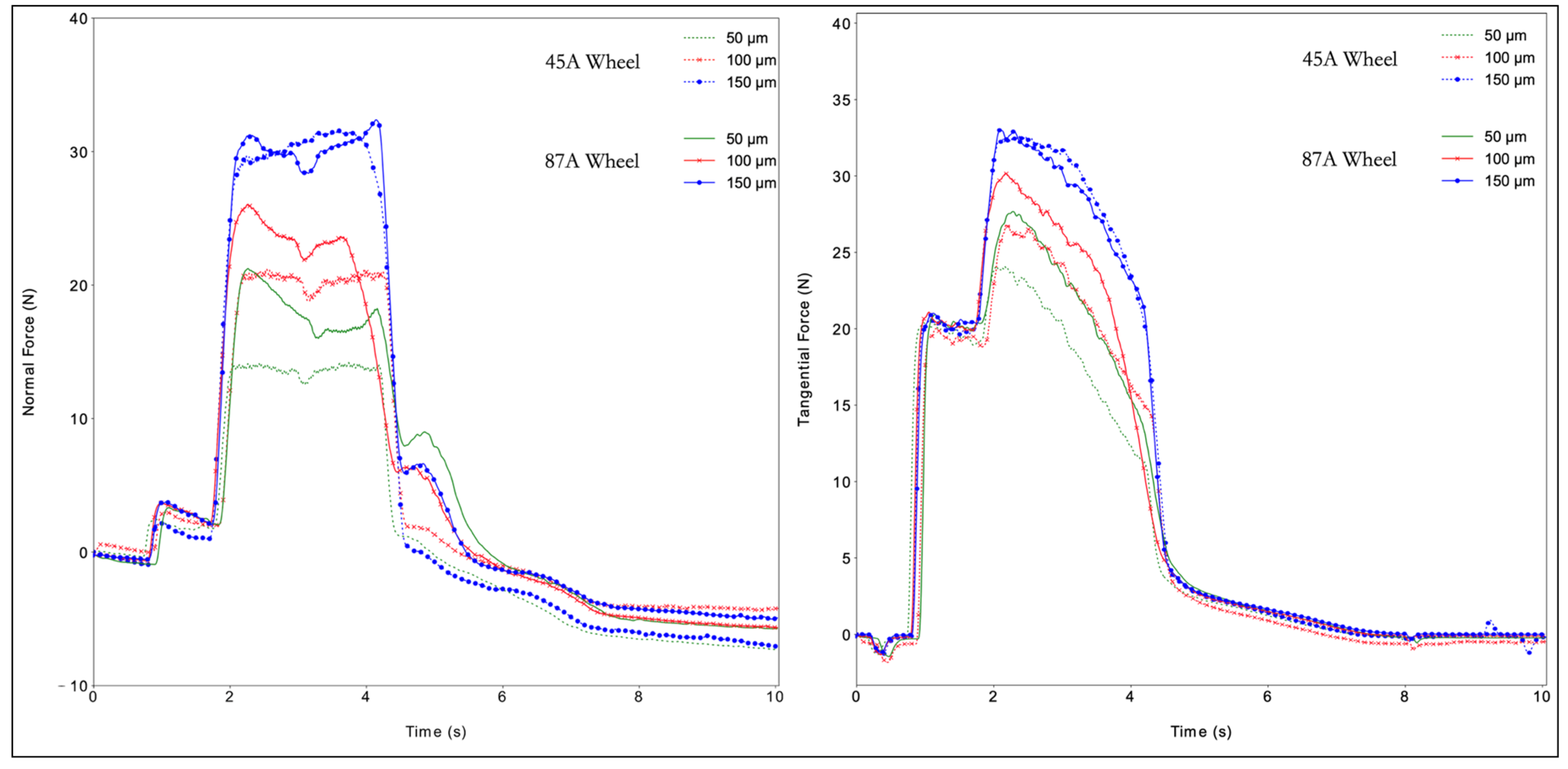
Observation of the normal and tangential forces (
Figure 5 and
Figure 6) shows that both forces grew with increased cutting depth. The reason for this behavior was an increase in the volume of material removed with an increase in the cutting depth. The DAQ tool monitored the cutting phenomena and the sample–tool interactions during machining. Some basic phenomena were detected. One was the exact position of the thermocouple hole in the acquisition of all data, detected by the slight deflection of the normal force values along the plateau. The second was that the wheel lost sharpness due to excessive material deformation, represented by a sudden force increase. The behavior of PA66GF30 was like that of PA66, showing an increase in force with an increase in the cutting depth. The normal forces were steadier and showed a smaller decrease in process efficiency. The tangential forces did not appear to be significantly affected by the presence of fibers. Another favorable aspect to examine was the spring back compensation of the normal force. The filled PA66 was less sensitive to an increase in cutting depth than the PA66. No significant differences existed for the two grinding wheels, with the exception of curves with
ae equal to 150. The decay in the tangential forces in all cases can be associated with the influence of the cutting fluid in the process. Because the nozzle is pointed in the same direction as the wheel moves, the amount of fluid directly applied to the surface reduces. However, the points where the wheel engages and disengages the piece are seen in the literature [
22,
23].
The main difference between power and force acquisition was the idle power, defined as the power spent during the spindle operation in a steady state before machining. There was no response to the application of the coolant because it happened in the tangential force. The grinding power
P is associated with the tangential force component
Ft, given by [
16]:
This value was compared with the total energy given by the machine’s spindle while cutting
Ptotal, and provided the energy partition
εp and the lost power
η [
20]:
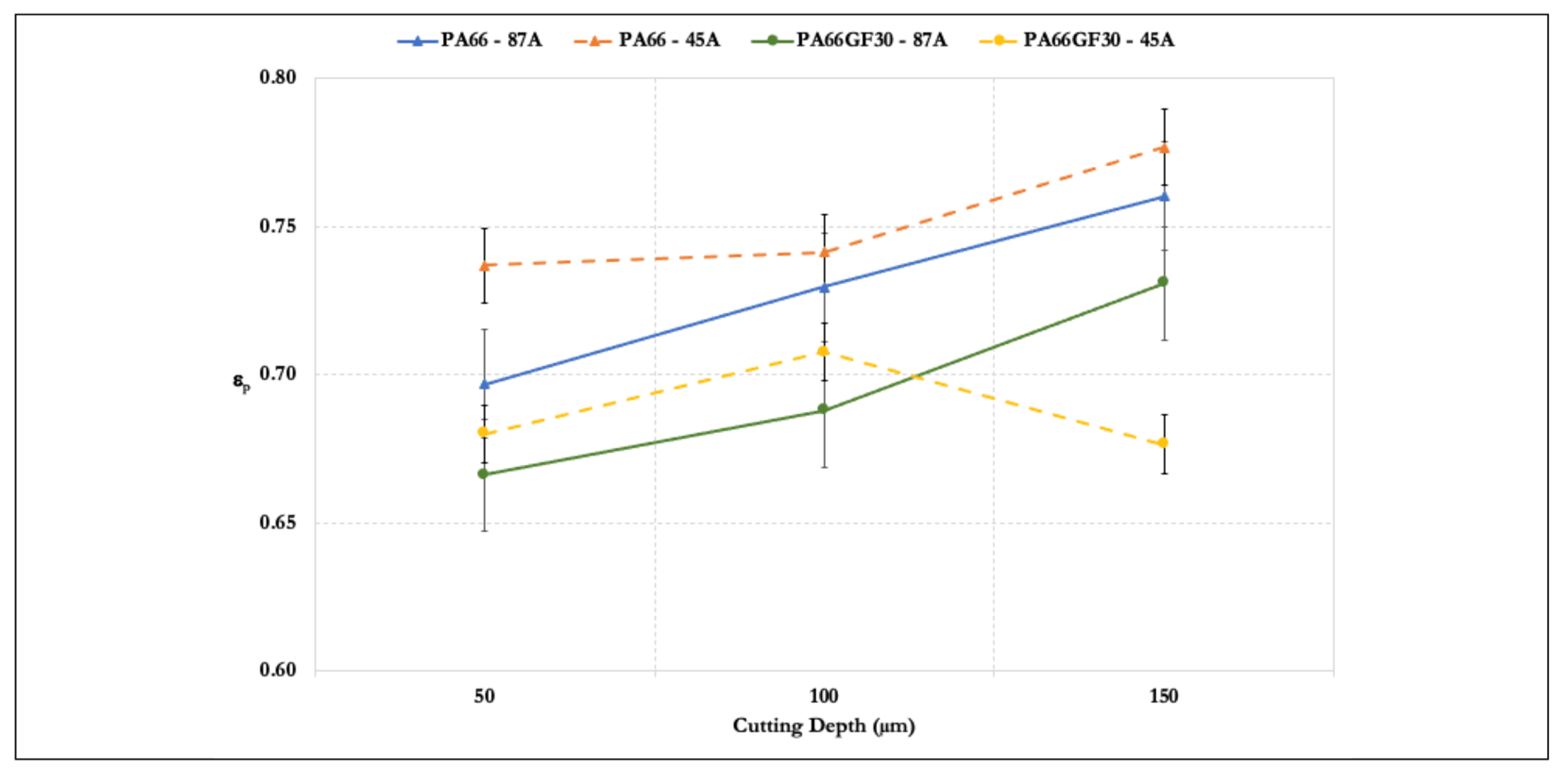
Results of the energy partition versus cutting depth are presented in
Figure 7. The grinding power increased with an increase in the cutting depth. Compared to the tangential forces, the cutting power values provided a better insight into the process behavior.
All gathered data of each sample were averaged to represent each cutting depth data point. Only for one set (PA66GF30, 45A wheel, and 150 µm), an increase in cutting depth denoted a loss of cutting partition and lost power increased. Energy partition was expected at some point as the cutting depth increased, because its increase caused the grains to be wholly immersed in the material that was to be removed, thus not providing an opportunity for the cutting edges to properly machine the surface. Moreover, the non-cutting surfaces, e.g., the bonding material, came into contact with the workpiece and increased the amount of rubbing and heat in the contact zone. In addition, there was no loss of power in the latter case, only a loss of energy partition because the process for these specific conditions reached a technological limit. The power at the spindle continuously increased because the machine complied with the parameters set by the operations. However, the value to effectively perform grinding changed. At that stage, the grains were too small for the cutting depth. They were not converting the spindle power as was possible at the other cutting depths and, instead, most of the energy given to the system was wasted as heat. This heat was directed to the grinding wheel–fluid system, rather than the workpiece, as evident from the temperature measurements and plowing of particles present in the cutting zone.
The decrease in lost power suggested that the process forces were dominant. As explained later, the power may be lost in other operations, such as plowing, chip formation, and temperature generation on the surface. Combining a high Peclet number (range 116–201) with optimal cooling did not allow for a large quantity of heat to be absorbed and passed to the workpiece. The Peclet number
Pe is given by:
where
vw is the infeed speed;
lg the geometrical contact length between the workpiece and the wheel, given by
lg =
ae ×
D; and α the thermal diffusivity [
24]. Most grinding operations are undertaken with
Pe equal to 1, balancing the convective transport with heat transport [
22]. A reduction of the thermal diffusivity
α, typical of a polymer, caused an increase in
Pe. The physical meaning was a reduction of the amount of heat transferred to the workpiece. No sensitive variations of temperature affecting the surface integrity were recorded; this was also the case for the highest cutting pass. The temperature in the experiment, with the cooling applied, did not present a significant increase, with a maximum variation of 5 °C. The direct contact between the grains and the workpiece generated heat. However, the advective transport rate was more effective than the diffusive transport rate. Most of the thermal energy entering the workpiece was transmitted to the coolant–grinding wheel system. The specific energy is:
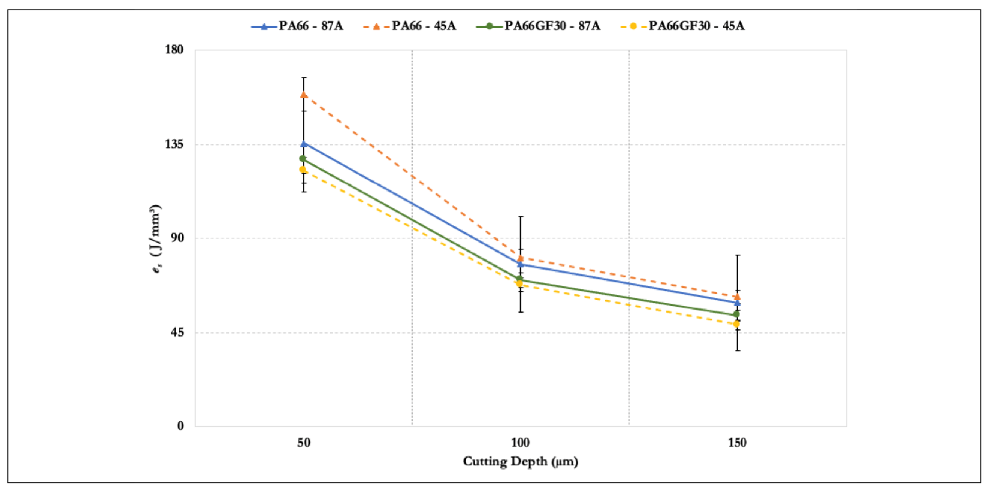
Results of the specific grinding energy
es are presented in
Figure 8. As previously discussed, the tangential force
Ft increased with the cutting depth. However, the ratio
Ft/
ae decreased because the increase in the cutting depth was more significant, with the other parameters in the equation being constant. Thus, the specific energy
es fell with a rise in the cutting depth. The overall trend was a reduction in the amount of energy to remove the material with increased cutting depth. The machining of PA66GF30 required less energy than that for PA66. The brittle nature of the composite promoted this behavior. An increase of 50 to 100 µm had a greater impact than an increase of 100 to 150 µm. The cutting depth increased three times, but the specific energy did not decay in the same order. This was another indicator that, for polyamides ground in these conditions, the specific energy converged to a value around 50 to 60 J/mm
3. As the figure shows, an increase from 50 to 100 µm caused a reduction in specific energy by 50% for all cases, whereas a rise from 100 to 150 µm resulted in a 30% reduction.
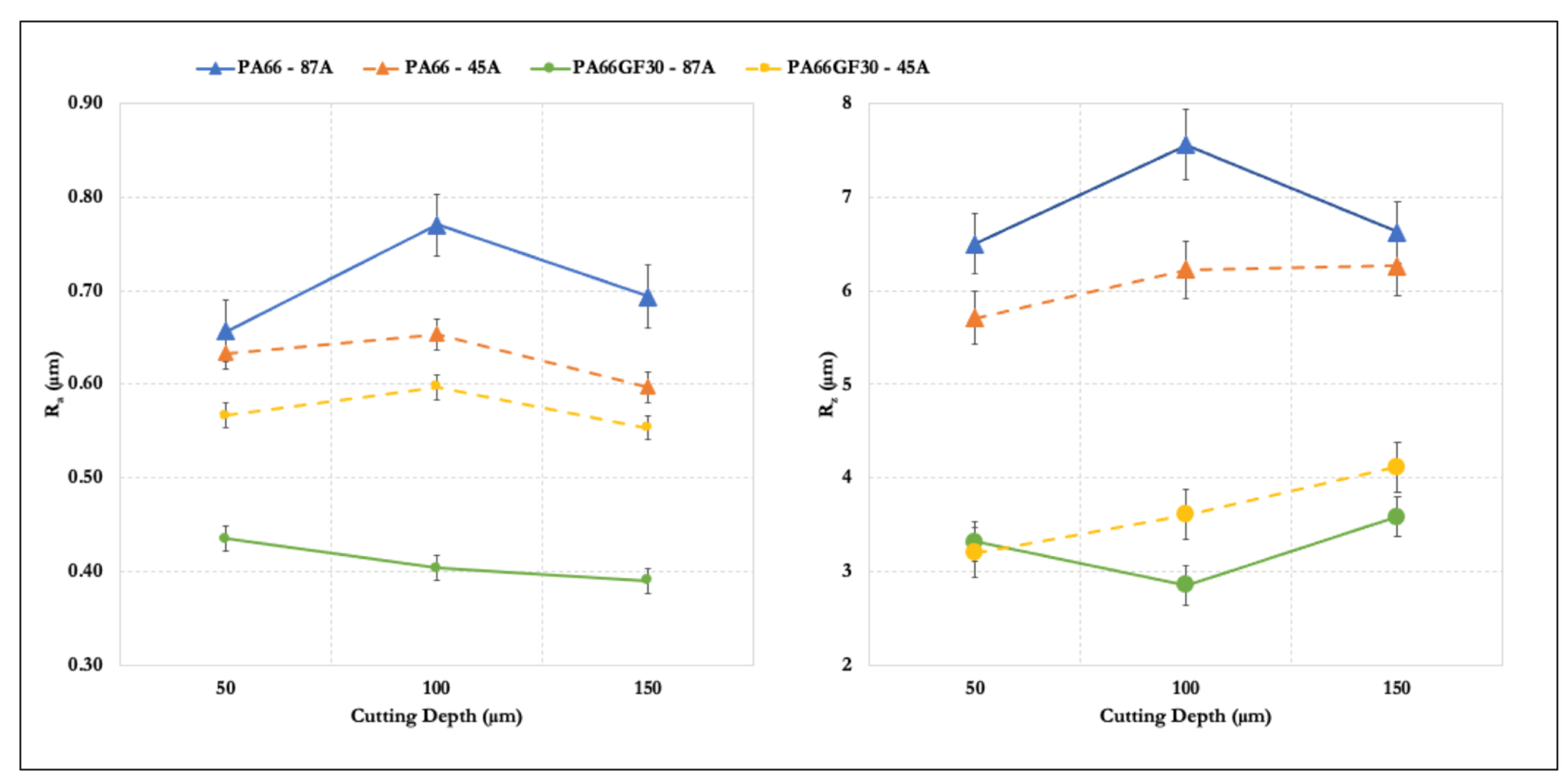
The surface quality indicators
Ra and
Rz enlarged the result analysis (
Figure 9). The two roughness parameters acted in an opposing manner with the variation of
ae.
Ra is a measurement of surface integrity because it is an arithmetic average of the entire sampling length. This measure provided a general idea of the quality of the surface, but averaged out most of the defects present in the specimen. In contrast,
Rz is an average of the five lowest valleys and the give highest peaks. This measure increased with an increase in the number of ploughing and rubbing zones. In this work, observation of both parameters was necessary because surface integrity is essential for materials this soft, and the fast evaluation of defects is essential to real-life production. Evaluating the surface with only one of these parameters would result in a disagreement between the results found from SEM, which showed a more damaged surface, and the resulting surface roughness. An increase in cutting depth to 150 μm produced a reduction in
Ra but an increase in
Rz. The grinding forces on ground specimens increased with an increased cutting depth, causing a decrease in surface quality caused by higher wheel wear. The workpiece speed increased, resulting in an increase in the plastic deformation and surface roughness. The larger the grinding depth and the longitudinal feed amount, the larger the plastic deformation, leading to a higher the surface roughness value. The grinding wheel has a high temperature, and the heat was dominant, so the cutting fluid was crucial. The use of cutting fluid reduced the temperature of the grinding zone and burns, and washed away sand and chips, thus preventing scratching of the workpiece and reducing the surface roughness value. The surface quality surpassed the results obtained by milling with a single pass of grinding. The surface quality of unfilled PA66 diminished with this procedure, and, curiously, it presented the same reduction at the highest level of the cutting depth as the previous experiment. Even at a controlled temperature, the material viscosity can interfere with its quality during machining operations. On the contrary, the filled PA66 better responded to grinding because of the presence of fiber. The volume of removed material was constant with the increase in the cutting depth because more grains reached the contact zone. Consequently, the groove depth on the ground surface left by each grain was smaller, improving the surface roughness. This was caused by the material’s resistance to its removal due to the high removal rate during one pass.
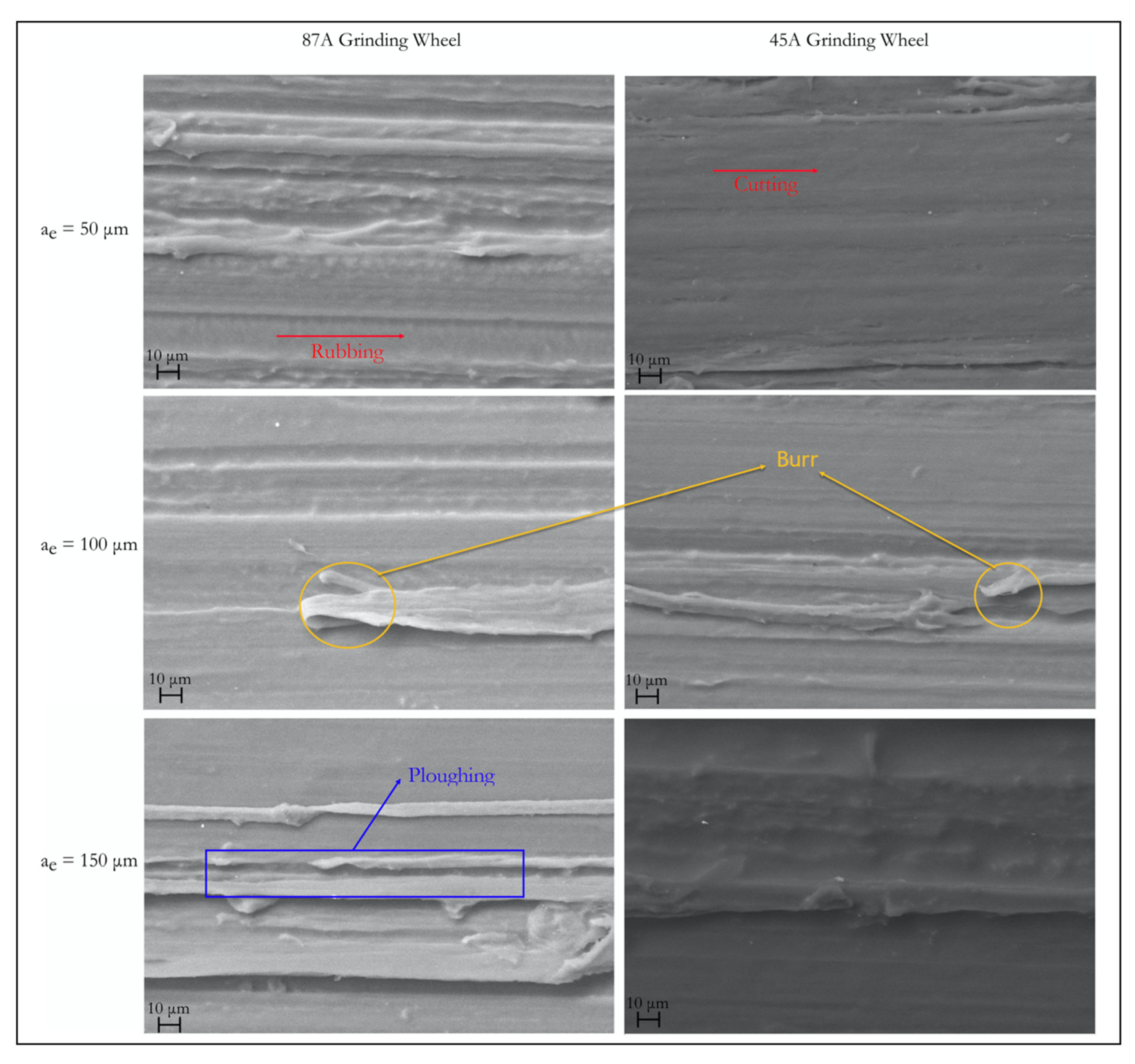
The SEM image of the surfaces enables a more in-depth analysis. As
Figure 10 shows, the amount of plastic flow and the incomplete cut for PA66 was more evident with an increase in cutting depth. Some rubbing zones existed where grains not aligned with the cutting height had little interaction with the surface. As the depth and the number of grains engaged in the zone increased, the material was not perfectly cut, leaving burrs and ploughing zones [
25].
The grains did not engage with the workpiece at the same height, despite dressing and truing the grinding wheel. Moreover, they had stochastic positions, angles, and dimensions—the specified granularity guaranteed only a specific range of dimensions. The grains had a certain tendency to break themselves during machining and form new cutting points.
For the filled PA66, the same type of surface defects was observed (
Figure 11). The fibers were almost all fractured and, as the cutting depth increased, they appeared to slowly position themselves along the cutting direction. The lower deformation at break possessed by the material facilitated a smoother ground surface, mainly in the matrix zone, and resulted in better surface quality of the samples. After grinding, the short fibers only presented fractures and a reduced number of pull-outs. Because the chosen parameters values were close to the fiber dimensions’ lengths, the process did not affect the surface roughness’s overall results. Observing all the SEM images, the lower cutting depths produced smoother zones (cutting), and the higher cutting depths showed a greater propensity to defects. The cutting wheel started with a very high volume of material to remove, the strain applied to the samples was higher, and the plastic deformation produced more burrs and ploughing.
The efficiency of the process was attributed to the low amount of heat lost to the piece due to the low diffusivity and the application of the coolant. Because the material temperatures remained stable below the glass transition, the resulting mechanical properties were more suitable for grinding. A less ductile material was removed more efficiently and produced more minor defects from plastic deformation. Another indication was the better surface quality of the filled materials. Although energy partition increased for all cases, with the exception of one, this behavior was expected to change while also observing the specific energy of the process. As es converges to a value, it can be interpreted as a constant for the material. In addition, because the forces continuously increased as the cutting depth increased, the value of energy to cut one cubic millimeter of material remained the same, and the forces were used for different physical mechanisms.


