
Mechanical Performance of Chairside Ceramic CAD/CAM Restorations and Zirconia Abutments with Different Internal Implant Connections: In Vitro Study and Finite Element Analysis


 ,
,
Abstract
1. Introduction
2. Materials and Methods
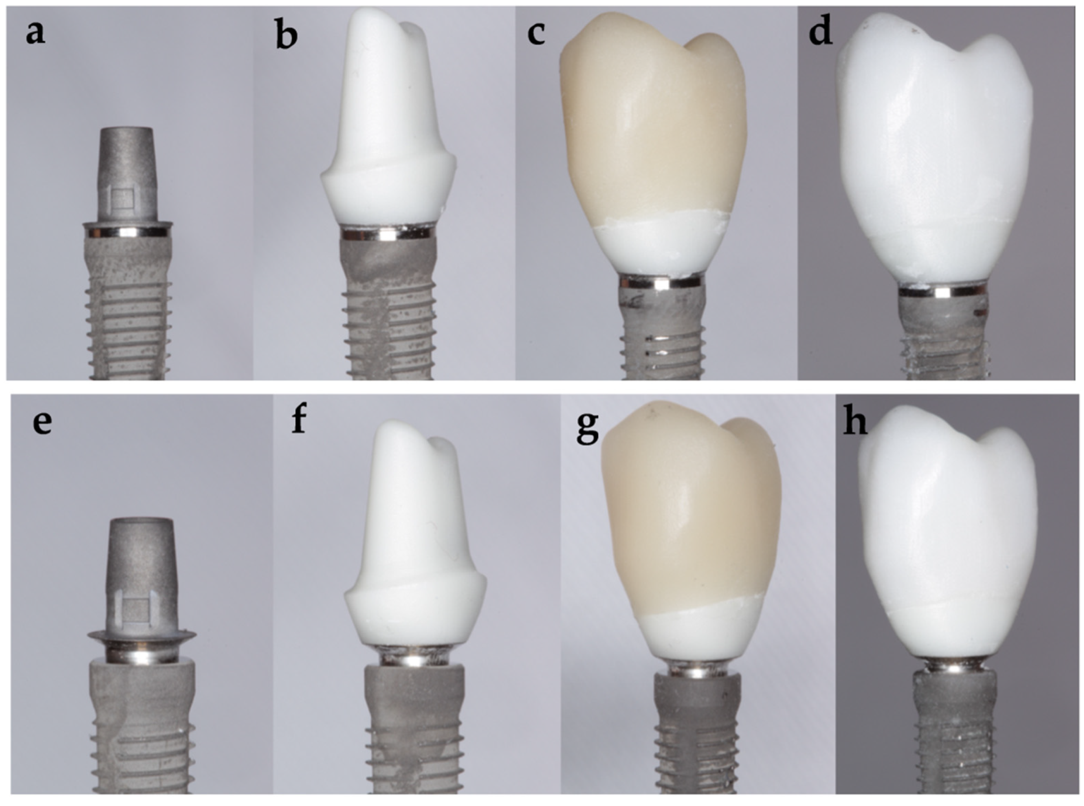
- Subgroup Tube ZZ: 15 specimens, using a tube in tube connection implant and a customized zirconia abutment with a monolithic zirconia CAD/CAM crown with standardized anatomy of a maxillary premolar.
- Subgroup Tube ZLD: 15 specimens, using a tube in tube connection implant and a customized zirconia abutment with a monolithic lithium disilicate CAD/CAM crown with standardized anatomy of a maxillary premolar.
- Subgroup Conical ZZ: 15 specimens, using a conical connection implant and a customized zirconia abutment with a monolithic zirconia CAD/CAM crown with standardized anatomy of a maxillary premolar.
- Subgroup Conical ZLD: 15 specimens, using a conical connection implant and a customized zirconia abutment with a monolithic lithium disilicate CAD/CAM crown with standardized anatomy of a maxillary premolar.
2.1. Specimens Manufacture
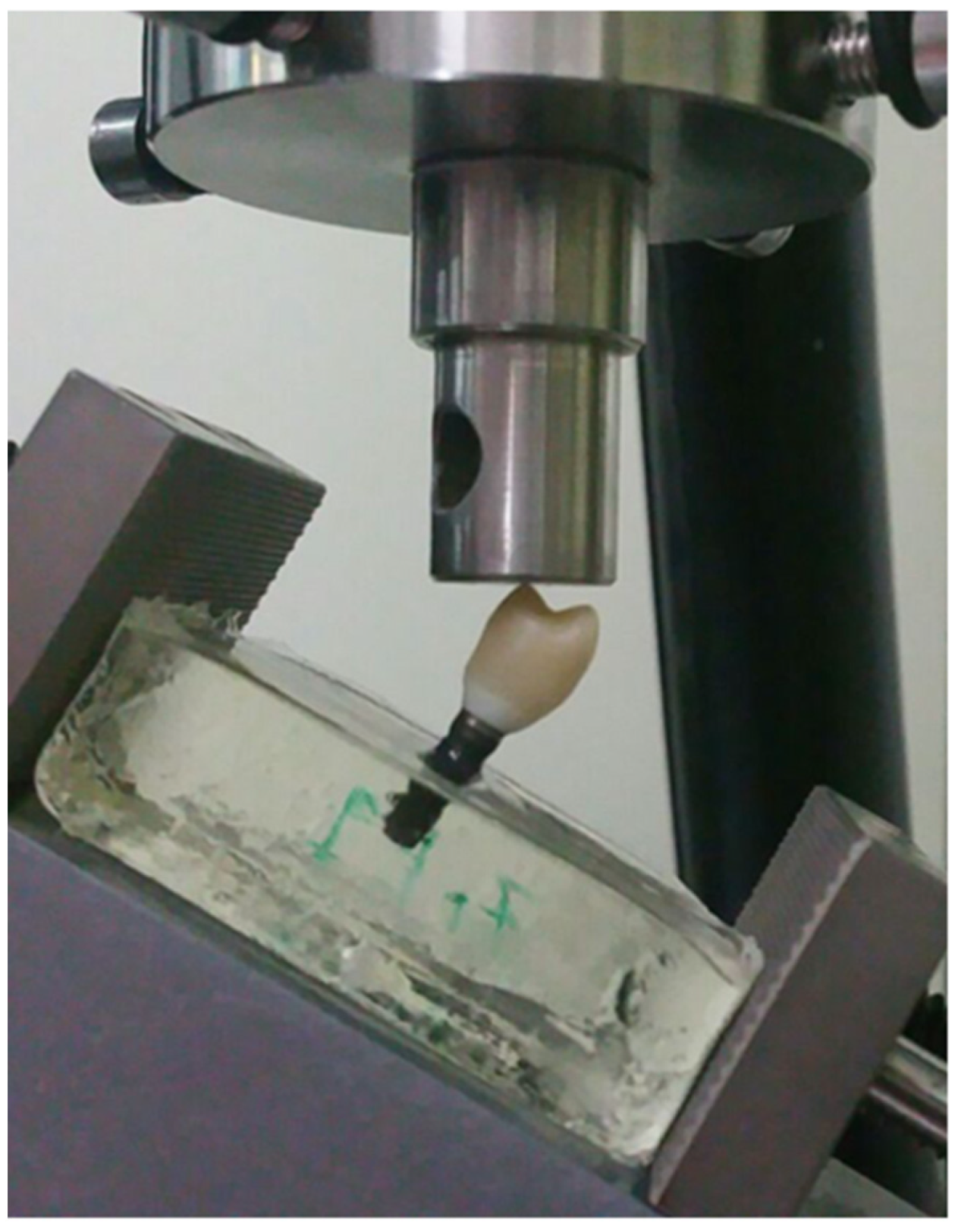
2.2. Mechanical Test
2.3. Statistical Analysis
2.4. Macro and Micro Structural Analysis
2.5. Finite Element Analysis
3. Results
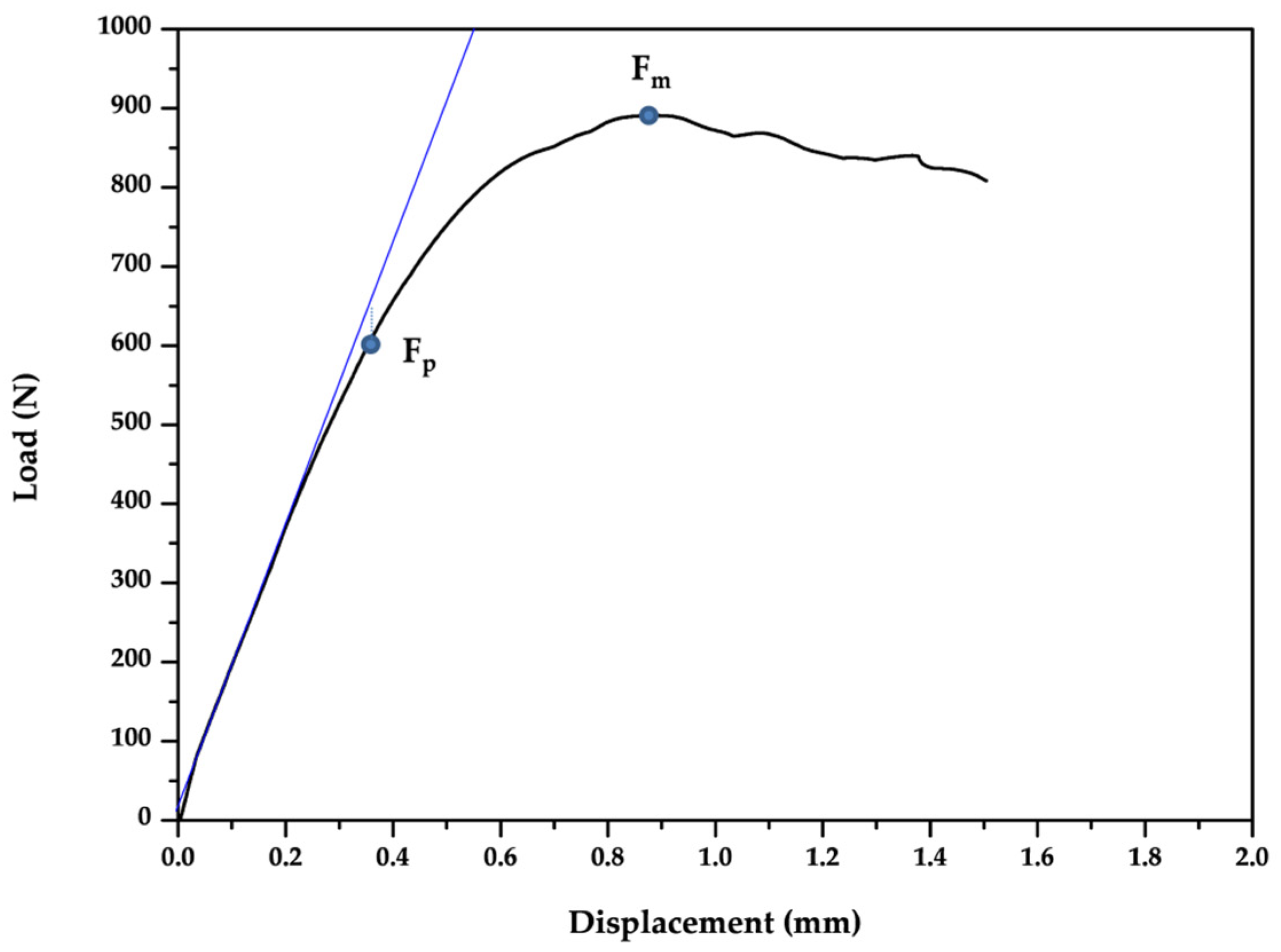
3.1. Static Load
3.2. Fatigue Behavior
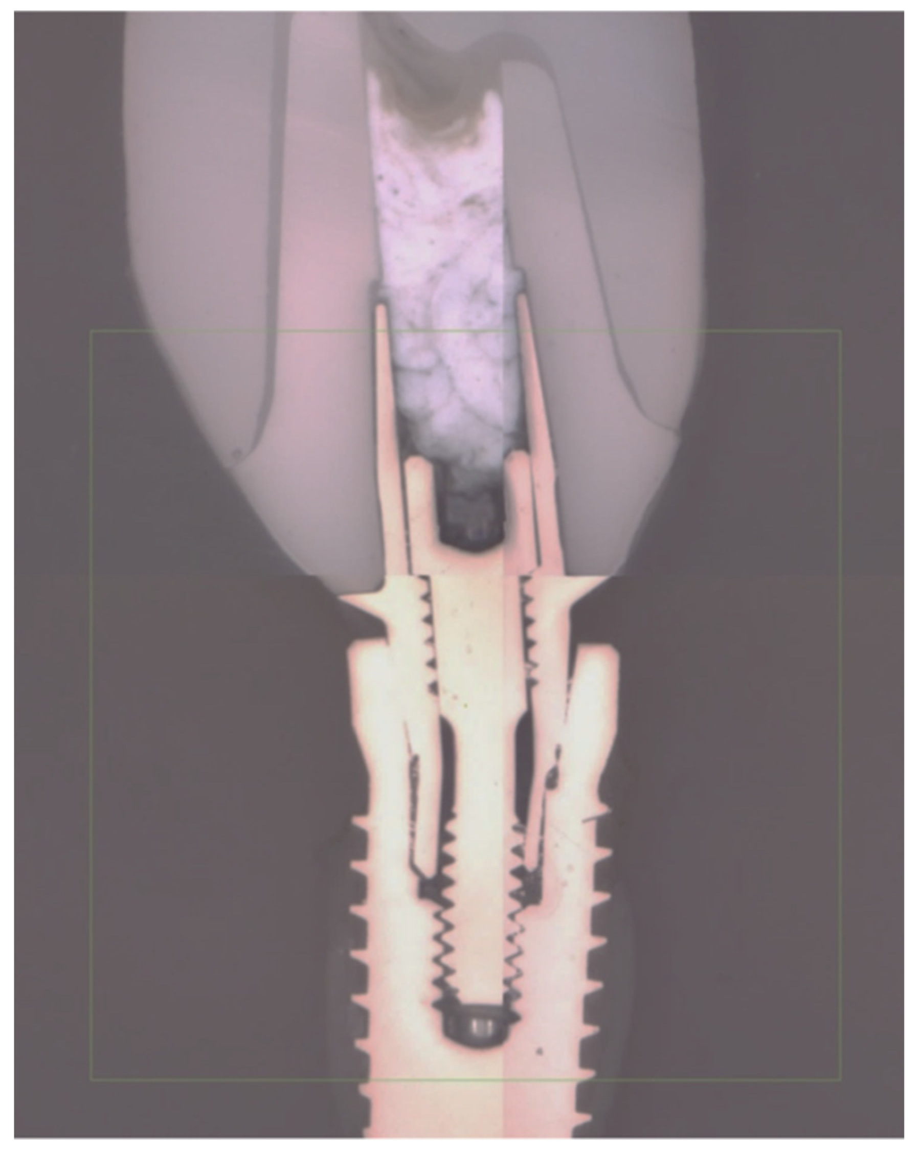
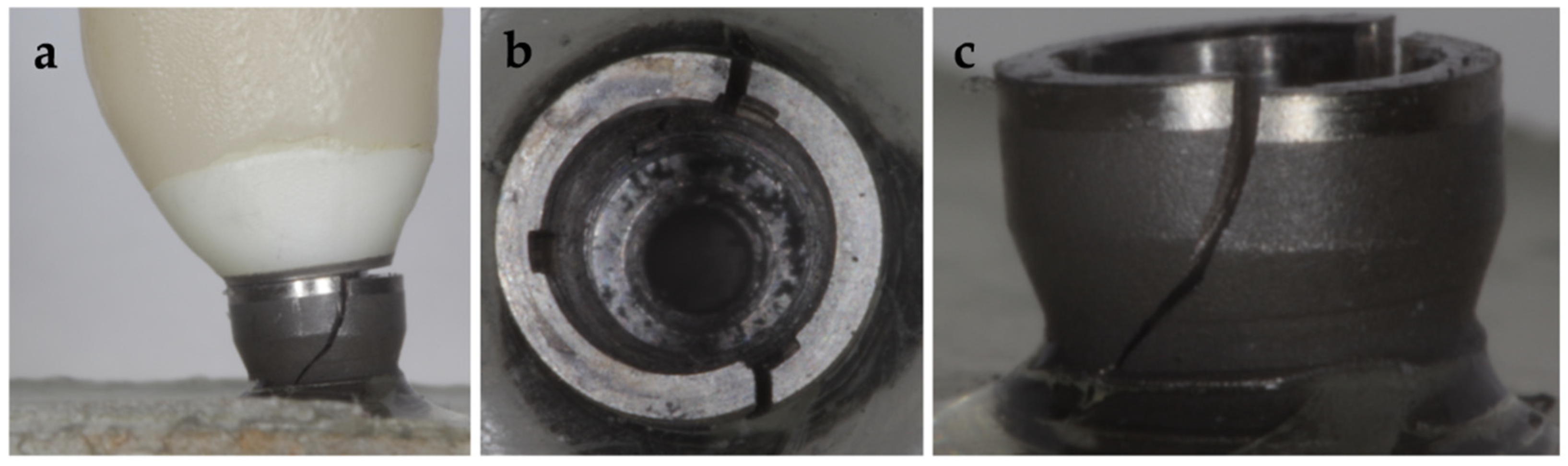
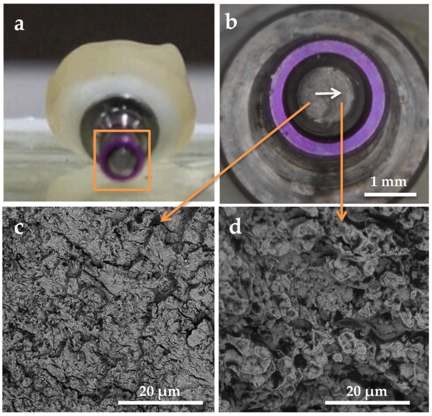
3.3. Failure Modes
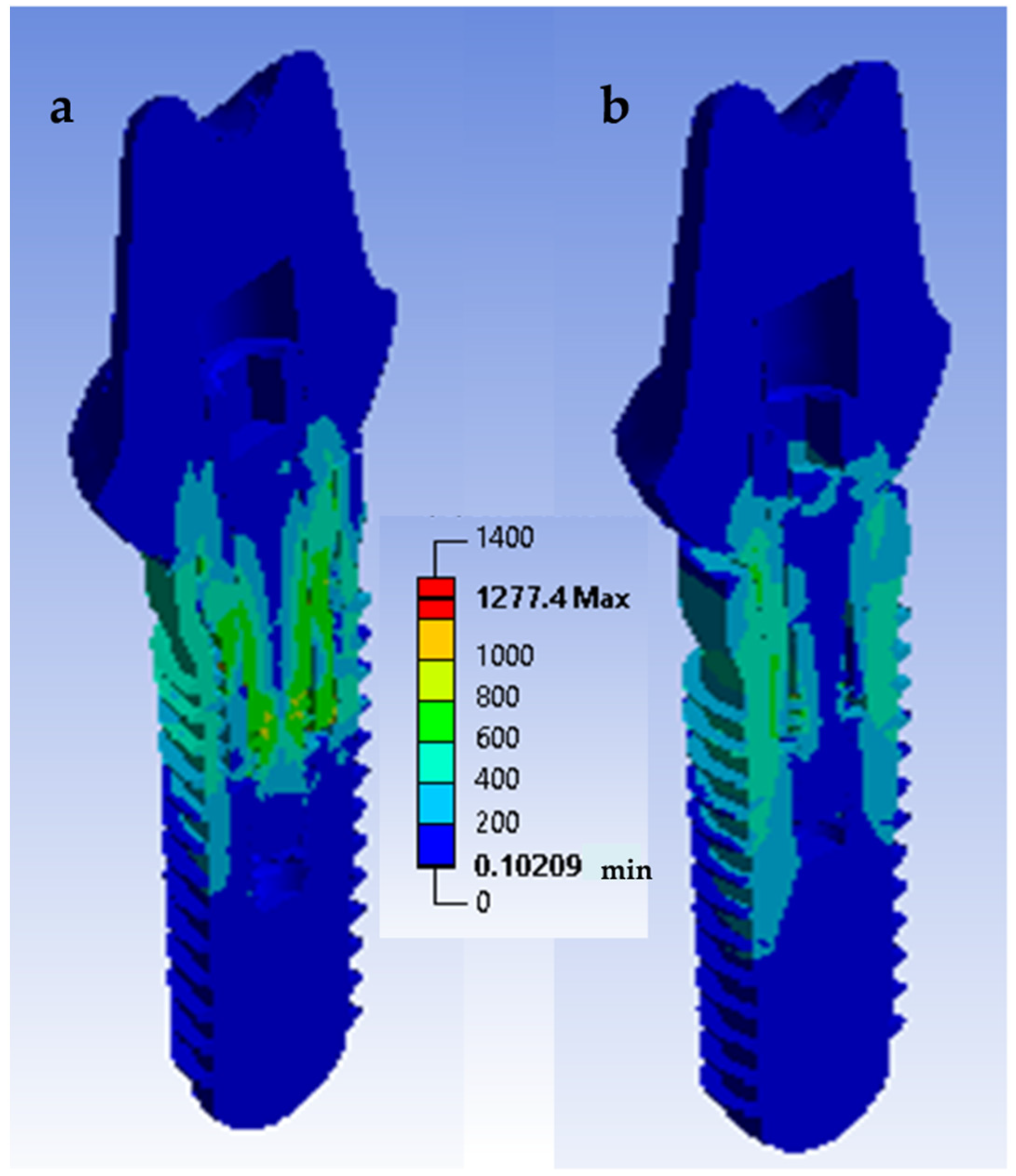
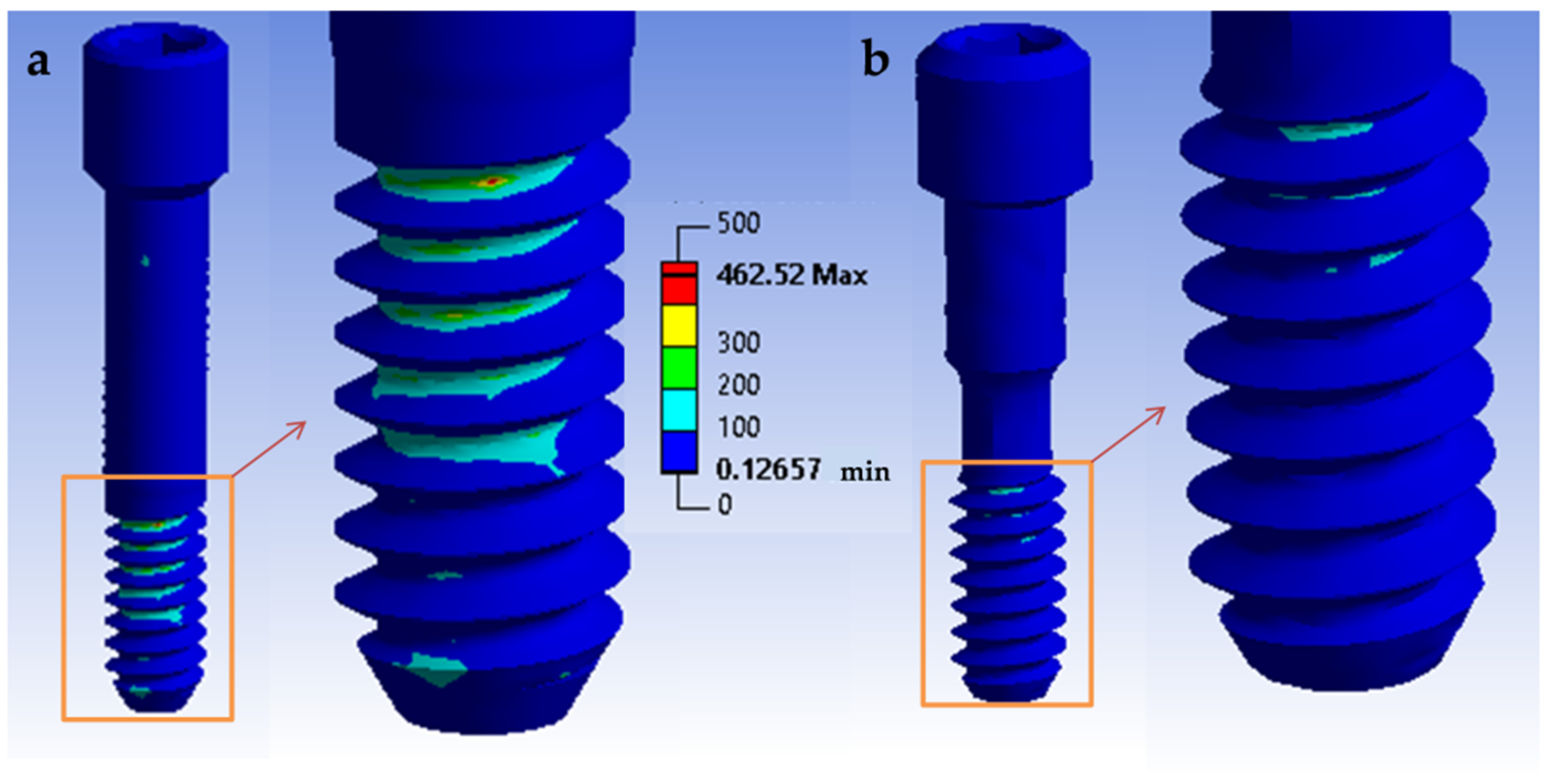
3.4. Finite Element Analysis
4. Discussion
5. Conclusions
- CAD/CAM zirconia abutments with conical implant−abutment connections for platform switching supporting single all-ceramic crowns made with a chairside workflow are highly reliable in terms of fracture resistance, both in static and in fatigue loads.
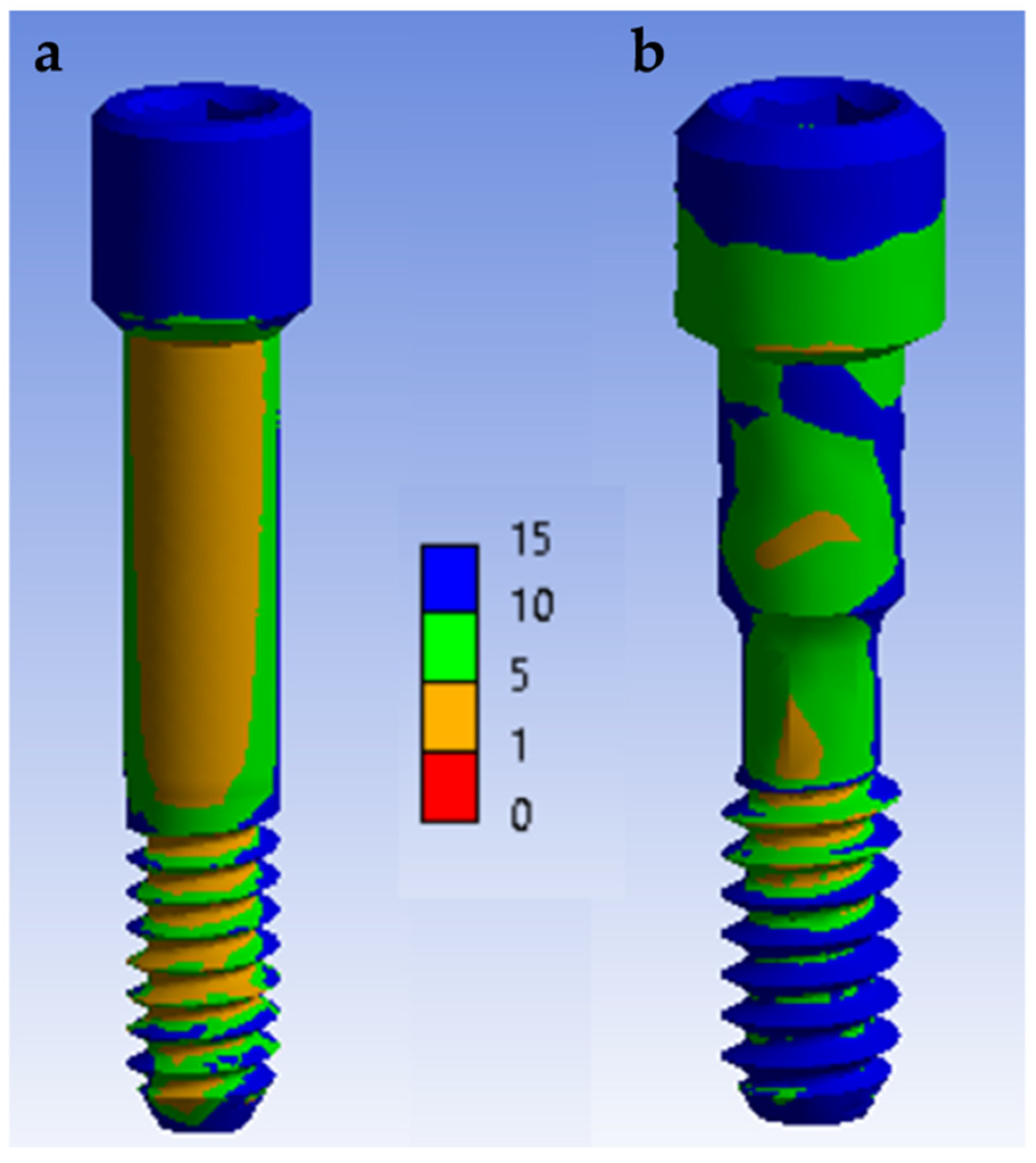
- The stress distribution affects the implant/restoration complex depending on the connection design. The component more susceptible to fracture is the screw. In the conical connection group, the screw is subjected to a lower stress level.
- The mechanical behavior of the restorative complex does not seem to be affected by the different crown materials (zirconia or lithium disilicate) used in this study.
Author Contributions
Funding
Institutional Review Board Statement
Informed Consent Statement
Data Availability Statement
Conflicts of Interest
References
- Sailer, I.; Zembic, A.; Jung, R.E.; Hämmerle, C.H.F.; Mattiola, A. Single-tooth implant reconstructions: Esthetic factors influencing the decision between titanium and zirconia abutments in anterior regions. Eur. J. Esthet. Dent. Off. J. Eur. Acad. Esthet. Dent. 2007, 2, 296–310. [Google Scholar]
- Fürhauser, R.; Florescu, D.; Benesch, T.; Haas, R.; Mailath, G.; Watzek, G. Evaluation of soft tissue around single-tooth implant crowns: The pink esthetic score. Clin. Oral Implant. Res. 2005, 16, 639–644. [Google Scholar] [CrossRef] [PubMed]
- Meijer, H.J.A.; Stellingsma, K.; Meijndert, L.; Raghoebar, G.M. A new index for rating aesthetics of implant-supported single crowns and adjacent soft tissues–the Implant Crown Aesthetic Index: A pilot study on validation of a new index. Clin. Oral. Implants Res. 2005, 16, 645–649. [Google Scholar] [CrossRef] [PubMed]
- Jung, R.E.; Holderegger, C.; Sailer, I.; Khraisat, A.; Suter, A.; Hämmerle, C.H. The effect of all-ceramic and porcelain-fused-to-metal restorations on marginal peri-implant soft tissue color: A randomized controlled clinical trial. Int. J. Periodontics Res. Dent. 2008, 28, 357–365. [Google Scholar]
- Bressan, E.; Paniz, G.; Lops, D.; Corazza, B.; Romeo, E.; Favero, G.A. Influence of abutment material on the gingival color of implant-supported all-ceramic restorations: A prospective multicenter study. Clin. Oral Implant. Res. 2011, 22, 631–637. [Google Scholar] [CrossRef]
- Martínez-Rus, F.; Prieto, M.; Salido, M.P.; Madrigal, C.; Özcan, M.; Pradíes, G. A Clinical Study Assessing the Influence of Anodized Titanium and Zirconium Dioxide Abutments and Peri-implant Soft Tissue Thickness on the Optical Outcome of Implant-Supported Lithium Disilicate Single Crowns. Int. J. Oral. Maxillofac. Implants. 2017, 32, 156–163. [Google Scholar] [CrossRef] [PubMed]
- López-Píriz, R.; Cabal, B.; Goyos-Ball, L. Current state-of-the-art and future perspectives of the three main modern implant-dentistry concerns: Aesthetic requirements, mechanical properties, and peri-implantitis prevention. J. Biomed. Mater Res. Part A 2019, 107, 1466–1475. [Google Scholar] [CrossRef]
- Suárez-López del Amo, F.; Lin, G.; Monje, A.; Galindo-Moreno, P.; Wang, H. Influence of soft tissue thickness on peri-implant marginal bone loss: A systematic review and meta-analysis. J. Periodontol. 2016, 87, 690–699. [Google Scholar] [CrossRef]
- Leinfelder, K.F.; Isenberg, B.P.; Essig, M.E. A new method for generating ceramic restorations: A CAD-CAM system. J. Am. Dent. Assoc. 1989, 118, 703–707. [Google Scholar] [CrossRef]
- Mörmann, W.H.; Brandestini, M. Cerec-System: Computerized inlays, onlays and shell veneers. Zahnarztliche Mitteilungen 1987, 77, 2400. [Google Scholar]
- Posselt, A.; Kerschbaum, T. Longevity of 2328 chairside Cerec inlays and onlays. Int. J. Comput. Dent. 2003, 6, 231–248. [Google Scholar]
- Rauch, A.; Reich, S.; Dalchau, L.; Schierz, O. Clinical survival of chair-side generated monolithic lithium disilicate crowns: 10-year results. Clin. Oral Investig. 2018, 22, 1763–1769. [Google Scholar] [CrossRef]
- Mörmann, W.H.; Bindl, A. The new creativity in ceramic restorations: Dental CAD-CIM. Quintessence Int. 1996, 27, 821–828. [Google Scholar]
- Rosentritt, M.; Hahnel, S.; Engelhardt, F.; Behr, M.; Preis, V. In vitro performance and fracture resistance of CAD/CAM-fabricated implant supported molar crowns. Clin. Oral Investig. 2017, 21, 1213–1219. [Google Scholar] [CrossRef]
- Hürzeler, M.; Fickl, S.; Zuhr, O.; Wachtel, H.C. Peri-implant bone level around implants with platform-switched abutments: Preliminary data from a prospective study. J Oral Maxillofac. Surg. 2007, 65, 33–39. [Google Scholar] [CrossRef]
- Canullo, L.; Rossi-Fedele, G.; Iannello, G.; Jepsen, S. Platform switching and marginal bone-level alterations: The results of a randomized-controlled trial. Clin. Oral Implant. Res. 2010, 21, 115–121. [Google Scholar] [CrossRef]
- Farronato, D.; Santoro, G.; Canullo, L.; Botticelli, D.; Maiorana, C.; Lang, N.P. Establishment of the epithelial attachment and connective tissue adaptation to implants installed under the concept of “platform switching”: A histologic study in minipigs. Clin. Oral Implants Res. 2012, 23, 90–94. [Google Scholar] [CrossRef]
- Rodríguez, X.; Vela, X.; Calvo-Guirado, J.L.; Nart, J.; Stappert, C.F.J. Effect of platform switching on collagen fiber orientation and bone resorption around dental implants: A preliminary histologic animal study. Int. J. Oral Maxillofac. Implant. 2012, 27, 1116–1122. [Google Scholar]
- Becker, J.; Ferrari, D.; Mihatovic, I.; Sahm, N.; Schaer, A.; Schwarz, F. Stability of crestal bone level at platform-switched non-submerged titanium implants: A histomorphometrical study in dogs. J. Clin. Periodontol. 2009, 36, 532–539. [Google Scholar] [CrossRef]
- Becker, J.; Ferrari, D.; Herten, M.; Kirsch, A.; Schaer, A.; Schwarz, F. Influence of platform switching on crestal bone changes at non-submerged titanium implants: A histomorphometrical study in dogs. J. Clin. Periodontol. 2007, 34, 1089–1096. [Google Scholar] [CrossRef]
- Chang, C.-L.; Chen, C.-S.; Hsu, M.-L. Biomechanical effect of platform switching in implant dentistry: A three-dimensional finite element analysis. Int. J. Oral Maxillofac. Implant. 2010, 25, 295–304. [Google Scholar]
- Baggi, L.; Cappelloni, I.; Di Girolamo, M.; Maceri, F.; Vairo, G. The influence of implant diameter and length on stress distribution of osseointegrated implants related to crestal bone geometry: A three-dimensional finite element analysis. J. Prosthet. Dent. 2008, 100, 422–431. [Google Scholar] [CrossRef]
- Maeda, Y.; Miura, J.; Taki, I.; Sogo, M. Biomechanical analysis on platform switching: Is there any biomechanical rationale? Clin. Oral Implants Res. 2007, 18, 581–584. [Google Scholar] [CrossRef]
- Geng, J.-P.; Tan, K.B.C.; Liu, G.-R. Application of finite element analysis in implant dentistry: A review of the literature. J. Prosthet. Dent. 2001, 85, 585–598. [Google Scholar] [CrossRef]
- Kayabaşı, O.; Yüzbasıoğlu, E.; Erzincanlı, F. Static, dynamic and fatigue behaviors of dental implant using finite element method. Adv. Eng. Softw. 2006, 37, 649–658. [Google Scholar] [CrossRef]
- Pradíes Ramiro, G.J.; Martínez Rus, F.; Valverde Espejo, A.R.; Fernández Antúnez, L.M. Automated Thermal Cycling Device and Method for Dentistry Materials. Universidad Complutense de Madrid; WO 2014/041217 Al. Patent P201200882, 20 March 2014. [Google Scholar]
- Fusayama, T.; Katayori, T.; Nomoto, S. Corrosion of Gold and Amalgam Placed in Contact with Each other. J. Dent. Res. 1963, 42, 1183–1197. [Google Scholar] [CrossRef]
- Odin, G.; Savoldelli, C.; Bouchard, P.-O.; Tillier, Y. Determination of Young’s modulus of mandibular bone using inverse analysis. Med. Eng. Phys. 2010, 32, 630–637. [Google Scholar] [CrossRef]
- Alonso-Pérez, R.; Bartolomé, J.F.; Ferreiroa, A.; Salido, M.P.; Pradíes, G. Evaluation of the Mechanical Behavior and Marginal Accuracy of Stock and Laser-Sintered Implant Abutments. Int. J. Prosthodont. 2017, 30, 136–138. [Google Scholar] [CrossRef]
- Pérez León, P.; Bartolomé, J.F.; Lombardía, C.; Pradíes, G. Mechanical fatigue behaviour of different lengths screw-retained restorations connected to two designs prosthetic connection level. J. Oral Rehabil. 2019, 46, 747–755. [Google Scholar] [CrossRef]
- Eden, P. ISO Norm 14801 (2016) Dynamic Loading Test for Endosseous Dental Implants; ISO: Geneva, Switzerland, 2016. [Google Scholar]
- Alonso-Pérez, R.; Bartolomé, J.F.; Ferreiroa, A.; Salido, M.P.; Pradíes, G. Original vs. non-original abutments for screw-retained single implant crowns: An in vitro evaluation of internal fit, mechanical behaviour and screw loosening. Clin. Oral Implants Res. 2018, 29, 1230–1238. [Google Scholar] [CrossRef]
- Delong, R.; Douglas, W. Development of an Artificial Oral Environment for the Testing of Dental Restoratives: Bi-axial Force and Movement Control. J. Dent. Res. 1983, 62, 32–36. [Google Scholar] [CrossRef]
- Morneburg, T.R.; Pröschel, P.A. Measurement of masticatory forces and implant loads: A methodologic clinical study. Int. J. Prosthodont. 2002, 15, 20–27. [Google Scholar] [PubMed]
- Gultekin, A.; Turkoglu, P.; Yalcin, S. Application of Finite Element Analysis in Implant Dentistry. In Finite Element Analysis—New Trends and Developments; Ebrahimi, F., Ed.; IntechOpen: London, UK, 2012; pp. 21–54. [Google Scholar]
- Gehrke, P.; Johannson, D.; Fischer, C.; Stawarczyk, B.; Beuer, F. In Vitro Fatigue and Fracture Resistance of One- and Two-Piece CAD/CAM Zirconia Implant Abutments. Int. J. Oral Maxillofac. Implant. 2015, 30, 546–554. [Google Scholar] [CrossRef]
- Robinson, D.; Aguilar, L.; Gatti, A.; Abduo, J.; Lee, P.V.S.; Ackland, D. Load response of the natural tooth and dental implant: A comparative biomechanics study. J. Adv. Prosthodont. 2019, 11, 169–178. [Google Scholar] [CrossRef]
- Garner, L.; Kotwal, N. Correlation Study of Incisive Biting Forces with Age, Sex, and Anterior Occlusion. J. Dent. Res. 1973, 52, 698–702. [Google Scholar] [CrossRef]
- Premkumar, S.; Sathyanarayana, H.P.; Manjula, W.S. Assessment of Maximum Voluntary Bite Force in Adults with Normal Occlusion and Different Types of Malocclusions. J. Contemp. Dent. Pr. 2012, 13, 534–538. [Google Scholar] [CrossRef]
- Fokas, G.; Ma, L.; Chronopoulos, V.; Janda, M.; Mattheos, N. Differences in micromorphology of the implant–abutment junction for original and third-party abutments on a representative dental implant. J. Prosthet. Dent. 2019, 121, 143–150. [Google Scholar] [CrossRef] [PubMed]
- Mattheos, N.; Larsson, C.; Ma, L.; Fokas, G.; Chronopoulos, V.; Janda, M. Micromorphological differences of the implant-abutment junction and in vitro load testing for three different titanium abutments on Straumann tissue level implants. Clin. Oral Implant. Res. 2017, 28, 1523–1531. [Google Scholar] [CrossRef]
- Tallarico, M.; Canullo, L.; Caneva, M.; Özcan, M. Microbial colonization at the implant-abutment interface and its possible influence on periimplantitis: A systematic review and meta-analysis. J. Prosthodont. Res. 2017, 61, 233–241. [Google Scholar] [CrossRef]
- Lopez-Piriz, R.; Solá-Linares, E.; Granizo, J.J.; Díaz-Güemes, I.; Enciso, S.; Bartolomé, J.F.; Cabal, B.; Esteban-Tejeda, L.; Torrecillas, R.; Moya, J.S. Radiologic Evaluation of Bone Loss at Implants with Biocide Coated Titanium Abutments: A Study in the Dog. PLoS ONE 2012, 7, e52861. [Google Scholar] [CrossRef]
- Martinez, A.; Guitián, F.; López-Píriz, R.; Bartolomé, J.F.; Cabal, B.; Esteban-Tejeda, L.; Torrecillas, R.; Moya, J.S. Bone Loss at Implant with Titanium Abutments Coated by Soda Lime Glass Containing Silver Nanoparticles: A Histological Study in the Dog. PLoS ONE 2014, 9, e86926. [Google Scholar] [CrossRef]
- Coppedê, A.R.; Bersani, E.; de Mattos, M.D.G.C.; Rodrigues, R.C.S.; de Mattias Sartori, I.A.; Ribeiro, R.F. Fracture resistance of the implant-abutment connection in implants with internal hex and internal conical connections under oblique compressive loading: An in vitro study. Int. J. Prosthodont. 2009, 22, 283–286. [Google Scholar]
- Merz, B.R.; Hunenbart, S.; Belser, U.C. Mechanics of the implant-abutment connection: An 8-degree taper compared to a butt joint connection. Int. J. Oral Maxillofac. Implant. 2000, 15, 519–526. [Google Scholar]
- Zipprich, H.; Weigl, P.; Ratka, C.; Lange, B.; Lauer, H.-C. The micromechanical behavior of implant-abutment connections under a dynamic load protocol. Clin. Implant. Dent. Relat. Res. 2018, 20, 814–823. [Google Scholar] [CrossRef] [PubMed]
- Joda, T.; Katsoulis, J.; Brägger, U. Clinical Fitting and Adjustment Time for Implant-Supported Crowns Comparing Digital and Conventional Workflows. Clin. Implant. Dent. Relat. Res. 2016, 18, 946–954. [Google Scholar] [CrossRef] [PubMed]


| Material and Implant Component | Elastic Modulus (GPa) | Poisson’s Ratio | Strength (MPa) | Yield Strength (MPa) |
|---|---|---|---|---|
| Titanium Grade 5 (Ti base and screw) [35] | 110 | 0.34 | 860 | 790 |
| Titanium Grade 4 (implant body) [35] | 110 | 0.34 | 550 | 480 |
| Zirconia (abutment and crown) [35] | 210 | 0.31 | 1000 | - |
| Lithium disilicate (crown) * | 95 | 0.23 | 360 | - |
| Epoxy resin (specimen holder) * | 4 | 0.33 | - | - |
| Model | Nodes | Elements | Minimum Edge Length (µm) |
|---|---|---|---|
| Tube connection | 151,091 | 91,032 | 5.6 |
| Conic connection | 95,726 | 55,521 | 1.4 |
| Subgroup | Maximum Load (Fm) N | Load at Plastic Deformation (Fp) N | Survival Cycles at a Maximum Load of 400 N |
|---|---|---|---|
| Conical ZZ | 1050 ± 92 | 704 ± 44 | 2 × 10⁶ |
| Conical ZLD | 1102 ± 112 | 682 ± 64 | 2 × 10⁶ |
| Tube ZZ | 1015 ± 73 | 552 ± 87 | 403.673 ± 85.398 |
| Tube ZLD | 975 ± 64 | 563 ± 66 | 254.577 ± 57.789 |
Publisher’s Note: MDPI stays neutral with regard to jurisdictional claims in published maps and institutional affiliations. |
© 2021 by the authors. Licensee MDPI, Basel, Switzerland. This article is an open access article distributed under the terms and conditions of the Creative Commons Attribution (CC BY) license (https://creativecommons.org/licenses/by/4.0/).
Share and Cite
Giner, S.; Bartolomé, J.F.; Gomez-Cogolludo, P.; Castellote, C.; Pradíes, G. Mechanical Performance of Chairside Ceramic CAD/CAM Restorations and Zirconia Abutments with Different Internal Implant Connections: In Vitro Study and Finite Element Analysis. Materials 2021, 14, 5009. https://doi.org/10.3390/ma14175009
Giner S, Bartolomé JF, Gomez-Cogolludo P, Castellote C, Pradíes G. Mechanical Performance of Chairside Ceramic CAD/CAM Restorations and Zirconia Abutments with Different Internal Implant Connections: In Vitro Study and Finite Element Analysis. Materials. 2021; 14(17):5009. https://doi.org/10.3390/ma14175009
Chicago/Turabian StyleGiner, Sergio, José F. Bartolomé, Pablo Gomez-Cogolludo, Carlos Castellote, and Guillermo Pradíes. 2021. "Mechanical Performance of Chairside Ceramic CAD/CAM Restorations and Zirconia Abutments with Different Internal Implant Connections: In Vitro Study and Finite Element Analysis" Materials 14, no. 17: 5009. https://doi.org/10.3390/ma14175009
APA StyleGiner, S., Bartolomé, J. F., Gomez-Cogolludo, P., Castellote, C., & Pradíes, G. (2021). Mechanical Performance of Chairside Ceramic CAD/CAM Restorations and Zirconia Abutments with Different Internal Implant Connections: In Vitro Study and Finite Element Analysis. Materials, 14(17), 5009. https://doi.org/10.3390/ma14175009