
Shape Analysis of the Elastic Deformation Region throughout the Axi-Symmetric Wire Drawing Process of ETP Grade Copper

 , ,
, ,
Abstract
1. Introduction
2. Industrial Approach and Application
3. Materials and Methods
4. Results and Discussion
4.1. Finite Element Method Simulations
4.2. Characterization of the Input Material’s Properties
4.3. Analysis of the Temperature Variations during the Process
4.4. Analysis of the Elastic Deformation Region
5. Conclusions
- (1)
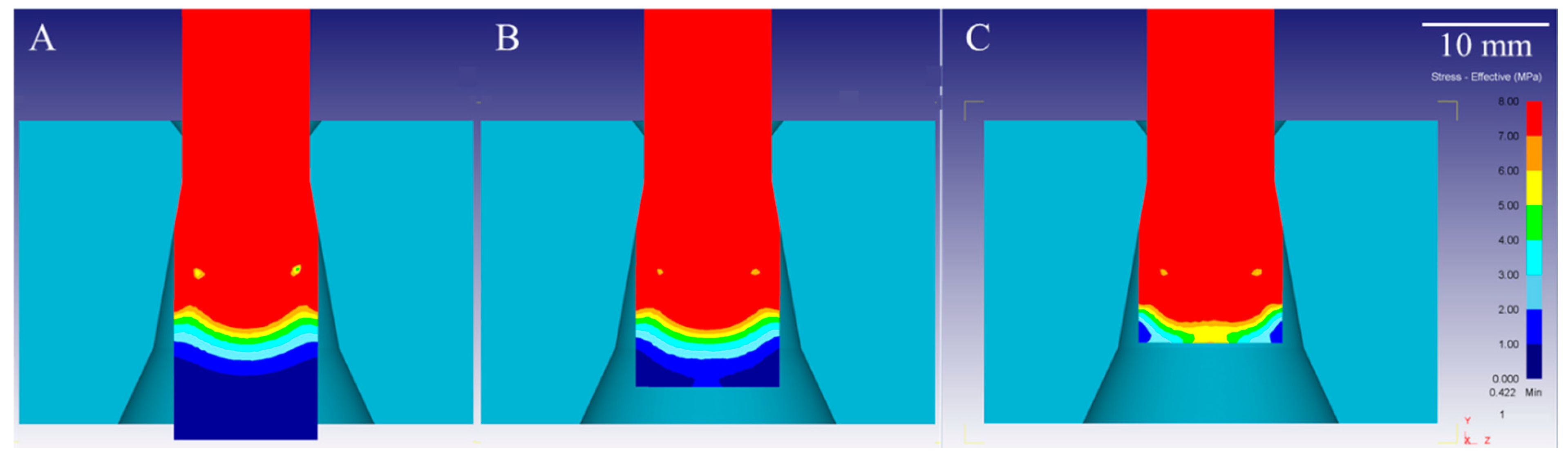
- The results of the FEM simulation indicate the differentiation of the shape of the elastic deformation region in stationary conditions, where a much greater range of deformations was recorded at the wire surface in comparison with non-stationary conditions, i.e., at the end of the process, where the values of elastic deformations are greater along the material axis.
- (2)
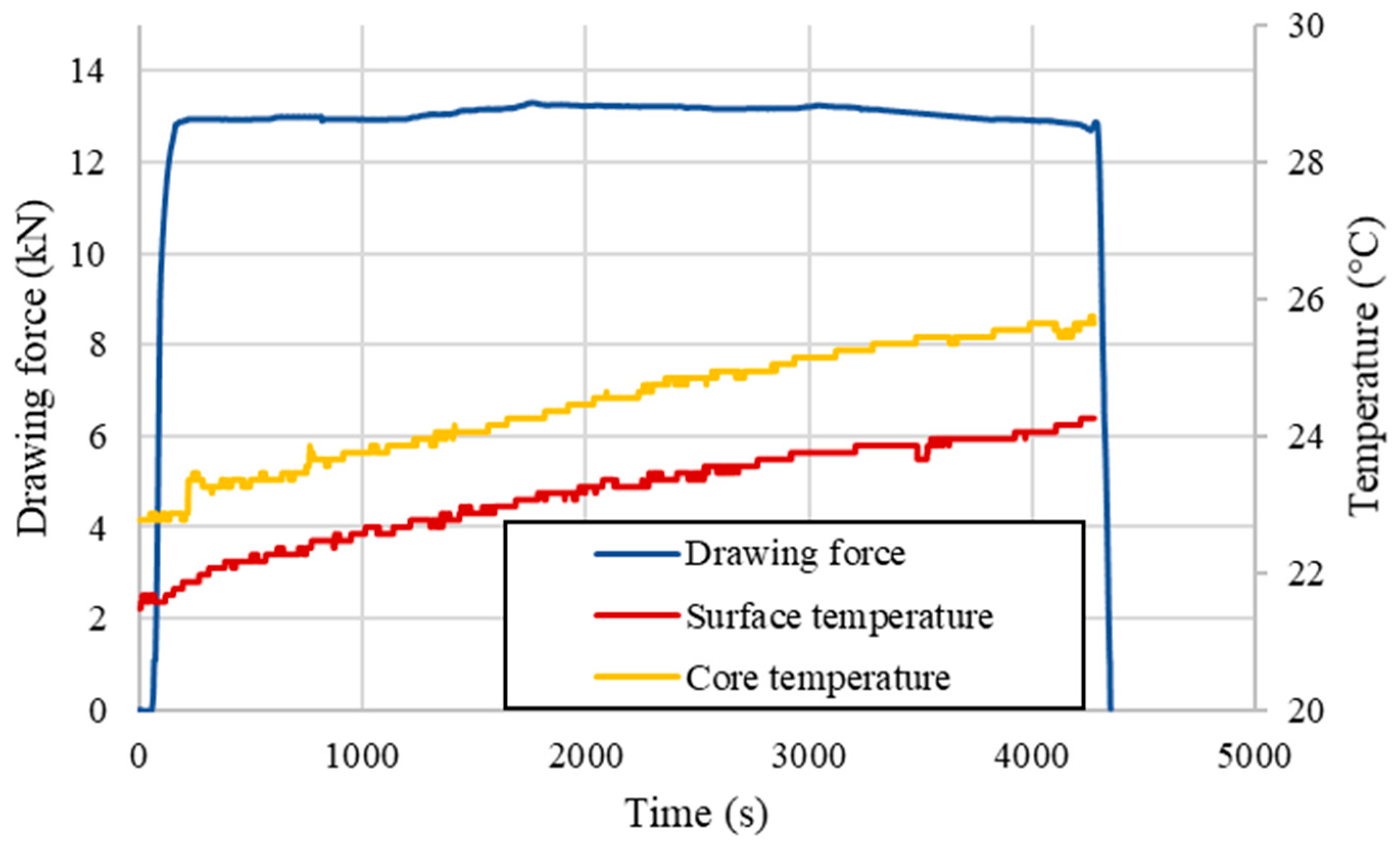
- The presence of the elastic deformation region was indirectly verified by drawing force measurements with different drawing parameters (various deformation coefficients λ). The increase in the recorded drawing force at the end of the process was related to the potential length of the elastic deformation region. It was proven that with the increase of the deformation coefficient, the length of this region increases even several times and can reach even 28.6 mm in length.
- (3)
- It was proven that the range of the elastic deformation region in non-stationary conditions is greater along the wire axis than at the surface using strain gauge method. In addition, it was stated that the length of the elastic deformation region at the surface of the drawn wire in stationary conditions is definitely greater than at the material surface in non-stationary conditions. The tests confirmed that the applied deformation coefficient affects the lengths and shape of the considered strain regions.
- (4)
- The hardness tests of samples taken from the cross-section in non-stationary phase of the process show that the recorded values at the axis were the highest with slightly lower values at the surface of the material and definitely the lowest in between. However, considering the samples taken from stationary conditions the measured values were higher at the edge of the material than at the axis, which confirms the differences in the amount of strain depending on the process phase. The greatest differences between the stationary and non-stationary conditions are visible at the axis of the drawn material. The measured values are again influenced by the applied deformation coefficient throughout the drawing process.
- (5)
- The shape of the elastic deformation region before entering the die reduction angle was confirmed to be in compliance with the FEM simulations conducted throughout this research paper among the tested areas.
Author Contributions
Funding
Institutional Review Board Statement
Informed Consent Statement
Data Availability Statement
Conflicts of Interest
References
- Blazynsky, T.Z. Design of Tools for Deformation Processes; Elsevier Applied Science Publishers Ltd.: Oxford, UK, 1986. [Google Scholar]
- Baron, H.G.; Thompson, F.C. Friction in wire drawing. J. Inst. Met. 1951, 78, 415. [Google Scholar]
- Strzępek, P.; Mamala, A.; Zasadzińska, M.; Franczak, K.; Jurkiewicz, B. Research on the drawing process of Cu and CuZn wires obtained in the cryogenic conditions. Cryogenics 2019, 100, 11–17. [Google Scholar] [CrossRef]
- Strzępek, P.; Mamala, A.; Smyrak, B.; Ściężor, W.; Zasadzińska, M. Research on the internal stresses in round wires obtained from AlMgSi alloy. In Proceedings of the 27th International Conference on Metallurgy and Materials, Brno, Czech Republic, 23–25 May 2018; pp. 1339–1344. [Google Scholar]
- Skołyszewski, A.; Paćko, M. Back tension value in the fine wire drawing proces. J. Mater. Process. Technol. 1998, 80–81, 380–387. [Google Scholar] [CrossRef]
- Łuksza, J. Components of Drawing Process; Uczelniane Wydawnictwa Naukowo-Dydaktyczne: Kraków, Poland, 2001. [Google Scholar]
- Wistreich, J.G. The fundamentals of wire drawing. Metall. Rev. 1958, 3, 97–142. [Google Scholar] [CrossRef]
- Avitzur, B. Handbook of Metal Forming Processes; Wiley: New York, NY, USA, 1983. [Google Scholar]
- Raskin, C.; Janssen, J. The causes of wire breakage during copper wire drawing. Wire J. Int. 1998, 31, 80–86. [Google Scholar]
- Knych, T. Elastic and Plastic Strains in Drawn Circular Sections; Uczelniane Wydawnictwa Naukowo-Dydaktyczne: Kraków, Poland, 2001. [Google Scholar]
- Pater, Z.; Samołyk, G. Fundamental Theories and Analysis of Metal Working; Podręczniki-Politechnika Lubelska: Lublin, Poland, 2011. [Google Scholar]
- Egea, A.J.S.; Rojas, H.A.G.; Celentano, D.J.; Perió, J.J.; Cao, J. Thermomechanical analysis of an electrically assisted wire drawing process. J. Manuf. Sci. Eng. 2017, 139, 111017. [Google Scholar] [CrossRef]
- Dobrov, I.V. On kinematics-of stock deformation process during drawing. Procedia Eng. 2017, 206, 760–770. [Google Scholar] [CrossRef]
- Gronostajski, Z.; Pater, Z.; Madej, L.; Gontarz, A.; Lisiecki, L.; Łukaszek-Sołek, A.; Łuksza, J.; Mróz, S.; Muskalski, Z.; Muzykiewicz, W.; et al. Recent development trends in metal forming. Arch. Civ. Mech. Eng. 2019, 19, 898–941. [Google Scholar] [CrossRef]
- Zimniak, Z.; Radkiewicz, G. The electroplastic effect in the cold-drawing of copper wires for the automotive industry. Arch. Civ. Mech. Eng. 2008, 8, 173–179. [Google Scholar] [CrossRef]
- Rojas, H.A.G.; Egea, A.J.S.; Hameed, S.; Bolmaro, R. An ultra-fast annealing treatment by electropulsing during pure copper wire drawing. Metals 2019, 9, 1253. [Google Scholar] [CrossRef]
- Strzępek, P.; Osuch, P.; Walkowicz, M.; Zasadzińska, M.; Mamala, A.; Knych, T.; Napióra, T. Impact of the heat treatment parameters on ultimate tensile strength, microstructure and wire drawing process of Zn-Al15. Metalurgija 2020, 59, 489–492. [Google Scholar]
- Kauffmann, A.; Freudenberger, J.; Klaus, H.; Klemm, V.; Schillinger, W.; Sarma, V.S.; Schultz, L. Properties of cryo-drawn copper with severely twinned microstructure. Mater. Sci. Eng. A 2013, 588, 132–141. [Google Scholar] [CrossRef]
- Kauffmann, A.; Freudenberger, J.; Klaus, H.; Schillinger, W.; Sarma, V.S.; Schultz, L. Efficiency of the refinement by deformation twinning in wire drawn single phase copper alloys. Mater. Sci. Eng. A 2015, 624, 71–78. [Google Scholar] [CrossRef]
- Hori, T.; Nakano, M.; Sasaki, A.; Utsunomiya, H. Wire drawing technique for strengthening of high-carbon steel wire by cryogenic uniform-deformation drawing. J. Jpn. Soc. Technol. Plast. 2014, 55, 863–867. [Google Scholar] [CrossRef][Green Version]
- Massé, T.; Fourment, L.; Montmitonnet, P.; Bobadilla, C.; Foissey, S. The optimal die semi-angle concept in wire drawing, examined using automatic optimization techniques. Int. J. Mater. Form. 2013, 6, 377–389. [Google Scholar] [CrossRef]
- Haddi, A.; Imad, A.; Vega, G. Analysis of temperature and speed effects on the drawing stress for improving the wire drawing process. Mater. Des. 2011, 32, 4310–4315. [Google Scholar] [CrossRef]
- Sas-Boca, I.M.; Tintelecan, M.; Pop, M.; Iluţiu-Varvara, D.A.; Mihu, A.M. The wire drawing process simulation and the optimization of geometry dies. Procedia Eng. 2017, 181, 187–192. [Google Scholar] [CrossRef]
- Perlin, I.L.; Ermanok, M.Z. Theory of Drawing; Metallurgy Publishers: Moscow, Russia, 1971. [Google Scholar]
- Martinez, G.A.S.; Qian, W.-L.; Kabayama, L.K.; Prisco, U. Effect of process parameters in copper-wire drawing. Metals 2020, 10, 105. [Google Scholar] [CrossRef]
- Martinez, G.A.S.; Dos Santos, E.F.; Kabayama, L.K.; Guidi, E.S.; Silva, F.D.A. Influences of different die bearing geometries on the wire-drawing process. Metals 2019, 9, 1089. [Google Scholar] [CrossRef]
- Amine, K.E.; Larsson, J.; Pejryd, L. Experimental comparison of roller die and conventional wire drawing. J. Mater. Process. Technol. 2018, 257, 7–14. [Google Scholar] [CrossRef]
- Zhang, S.H.; Liu, G.; Chen, D.; Zhang, Q.Y.; Jiang, X.R.; You, F.X. Plastic mechanical analysis of drawing force based on a twin elliptical die. Appl. Math. Model. 2020, 77, 1446–1459. [Google Scholar] [CrossRef]
- Vega, G.; Haddi, A.; Imad, A. Investigation of process parameters effect on the copper-wire drawing. Mater. Des. 2009, 30, 3308–3312. [Google Scholar] [CrossRef]
- Tintelecan, M.; Sas-Boca, I.M.; Iluţiu-Varvara, D.A. The influence of the dies geometry on the drawing force for steel wires. Procedia Eng. 2017, 181, 193–199. [Google Scholar] [CrossRef]
- Zasadzińska, M.; Knych, T.; Strzępek, P.; Jurkiewicz, B.; Franczak, K. Analysis of the strengthening and recrystallizationof electrolytic copper (Cu-ETP) and oxygen freecopper (Cu-OF). Arch. Civ. Mech. Eng. 2019, 19, 186–193. [Google Scholar] [CrossRef]
- Brandt, I.S.; Tumelero, M.A.; Pelegrini, S.; Zangari, G. Electrodeposition of Cu2O: Growth, properties, and applications. J. Solid State Electrochem. 2017, 21, 1999–2020. [Google Scholar] [CrossRef]
- Minami, T.; Nishi, Y.; Miyata, T. Cu2O-based solar cells using oxide semiconductors. J. Semicond. 2016, 37, 014002. [Google Scholar] [CrossRef]
- Zasadzińska, M.; Knych, T.; Smyrak, B.; Strzępek, P. Investigation of the dendritic structure influence on the electrical and mechanical properties diversification of the continuously casted copper strand. Materials 2020, 13, 5513. [Google Scholar] [CrossRef] [PubMed]
- Xu, D.C.; Zhai, S.Y.; Cheng, H.Y.; Guadie, A.; Wang, H.C.; Han, J.L.; Liu, C.Y.; Wang, A.J. Wire-drawing process with graphite lubricant as an industrializable approach to prepare graphite coated stainless-steel anode for bioelectrochemical systems. Environ. Res. 2020, 191, 110093. [Google Scholar] [CrossRef] [PubMed]
- Byon, S.M.; Lee, S.J.; Lee, D.W.; Lee, Y.H.; Lee, Y. Effect of coating material and lubricant on forming force and surface defects in wire drawing process. Trans. Nonferrous Met. Soc. China 2011, 21, 104–110. [Google Scholar] [CrossRef]
- Zuev, L.B.; Danilov, V.; Konovalov, S.; Filip’ev, R.A.; Gromov, V.E. Influence of contact potential difference and electric potential on the microhardness of metals. Phys. Solid State 2009, 51, 1137–1141. [Google Scholar] [CrossRef]
- Orlova, D.V.; Danilov, V.I.; Zuev, L.B. Character of variation in the microhardness of the (0001) plane of Zn single crystals under the action of electrostatic field and the possible reason for this effect. Phys. Solid State 2013, 55, 353–357. [Google Scholar] [CrossRef]
- Shen, F.; Ke, L.-L. Numerical study of coupled electrical-thermal-mechanical-wear behavior in electrical contacts. Metals 2021, 11, 955. [Google Scholar] [CrossRef]
- Egea, A.J.S.; Rojas, H.A.G.; Celentano, D.J.; Travieso-Rodriguez, J.A.; Fuentes, J.L. Electroplasticity-assisted bottom bending process. J. Mater. Process. Technol. 2014, 11, 2261–2267. [Google Scholar] [CrossRef]
- Kim, H.; Lee, K.; Kim, J.; Lee, C.; Jung, Y.; Kang, S. A study on the friction stir welding experiment and simulation of the fillet joint of extruded aluminum material of electric vehicle frame. Appl. Sci. 2020, 10, 9103. [Google Scholar] [CrossRef]
- Sivák, P.; Frankovský, P.; Delyová, I.; Bocko, J.; Kostka, J.; Schürger, B. Influence of different strain hardening models on the behavior of materials in the elastic–plastic regime under cyclic loading. Materials 2020, 13, 5323. [Google Scholar] [CrossRef]
- Tabor, D. The hardness of solids. Rev. Phys. Technol. 1970, 1, 145–171. [Google Scholar] [CrossRef]
- Valberg, H.S. Applied Metal Forming Including FEM Analysis; Cambridge University Press: Cambridge, UK, 2010. [Google Scholar]


| Cu | Ag | Bi | Pb | Sb | Sn | Zn | S | O | Other |
|---|---|---|---|---|---|---|---|---|---|
| (wt %) | |||||||||
| 99.97 | 0.00128 | 0.00002 | 0.00012 | 0.00003 | 0.00003 | 0.00003 | 0.0052 | 0.02 | Rest |
| Group | Parameter | Wire—Cu-ETP | Die—TC |
|---|---|---|---|
| Material properties | Young modulus (GPa) | 119 | 496 |
| Poisson’s ratio (-) | 0.35 | 0.24 | |
| Model of plastic flow | - | ||
| Other boundary conditions | Model of friction | Coulomb | |
| Friction coefficient | µ = 0.07 | ||
| Initial true strain before drawing | 1.1 | ||
| Discretization | Type of mesh | Tetrahedrons | Tetrahedrons |
| Number of elements | 50,000 | 100,000 | |
| Parameter | Input Material φ 11.55 mm |
|---|---|
| Young’s modulus (ultrasonic) (GPa) | 118 |
| Young’s modulus (strain gauges) (GPa) | 119 |
| Poisson’s ratio (ultrasonic) (-) | 0.36 |
| Poisson’s ratio (strain gauges) (-) | 0.35 |
| Ultimate Tensile Strength (MPa) | 388 |
| Yield Strength (MPa) | 385 |
| Vickers hardness (HV1) | 115.2 |
| Vickers microhardness (HV0.3) | 115.9 |
| Parameter | Value | |
|---|---|---|
| Diameter (mm) | 10 | |
| 2α die angle (°) | 16 | |
| Bearing length (mm) | 1 | |
| Deformation coefficient (λ) (-) | 1.1 | 1.33 |
| Calculated velocity of the material before entering the drawing die (mm/s) | 0.0928 | 0.0767 |
| Calculated velocity of the material inside the deformation region (mm/s) | 0.0976 | 0.0895 |
| Measured velocity of the material after exiting the drawing die (mm/s) | 0.1023 | |
| Parameter | Value | |
|---|---|---|
| Deformation coefficient (λ) (-) | 1.1 | 1.33 |
| Average drawing force (kN) | 6.45 | 14.39 |
| Recorded time of the drawing force increase (s) | 76 | 373 |
| Estimated length of the elastic region (mm) | 7.1 | 28.6 |
| Parameter | Value | |||
|---|---|---|---|---|
| Deformation coefficient (λ) (-) | 1.1 | 1.33 | ||
| Strain gauge in the radial direction | ||||
| Recorded time of the drawing force increase (s) | 91 | 140 | ||
| Estimated length of the elastic region (mm) | 8.44 | 10.74 | ||
| Recorded strain value (‰) | 0.45 | 2.02 | ||
| Strain gauge in the axial direction | ||||
| Conditions of the measurement (stationary (S)/non-stationary (N)) | S | N | S | N |
| Recorded time of the drawing force increase (s) | 100 | 49 | 152 | 119 |
| Estimated length of the elastic region (mm) | 9.28 | 4.55 | 11.66 | 9.13 |
| Recorded maximum strain value (‰) | 0.42 | 1.33 | 0.71 | 2.36 |
Publisher’s Note: MDPI stays neutral with regard to jurisdictional claims in published maps and institutional affiliations. |
© 2021 by the authors. Licensee MDPI, Basel, Switzerland. This article is an open access article distributed under the terms and conditions of the Creative Commons Attribution (CC BY) license (https://creativecommons.org/licenses/by/4.0/).
Share and Cite
Strzępek, P.; Mamala, A.; Zasadzińska, M.; Kiesiewicz, G.; Knych, T.A. Shape Analysis of the Elastic Deformation Region throughout the Axi-Symmetric Wire Drawing Process of ETP Grade Copper. Materials 2021, 14, 4713. https://doi.org/10.3390/ma14164713
Strzępek P, Mamala A, Zasadzińska M, Kiesiewicz G, Knych TA. Shape Analysis of the Elastic Deformation Region throughout the Axi-Symmetric Wire Drawing Process of ETP Grade Copper. Materials. 2021; 14(16):4713. https://doi.org/10.3390/ma14164713
Chicago/Turabian StyleStrzępek, Paweł, Andrzej Mamala, Małgorzata Zasadzińska, Grzegorz Kiesiewicz, and Tadeusz Antoni Knych. 2021. "Shape Analysis of the Elastic Deformation Region throughout the Axi-Symmetric Wire Drawing Process of ETP Grade Copper" Materials 14, no. 16: 4713. https://doi.org/10.3390/ma14164713
APA StyleStrzępek, P., Mamala, A., Zasadzińska, M., Kiesiewicz, G., & Knych, T. A. (2021). Shape Analysis of the Elastic Deformation Region throughout the Axi-Symmetric Wire Drawing Process of ETP Grade Copper. Materials, 14(16), 4713. https://doi.org/10.3390/ma14164713