
Structure and Properties of Barium Titanate Lead-Free Piezoceramic Manufactured by Binder Jetting Process


Abstract
1. Introduction
2. Materials and Methods
2.1. Materials
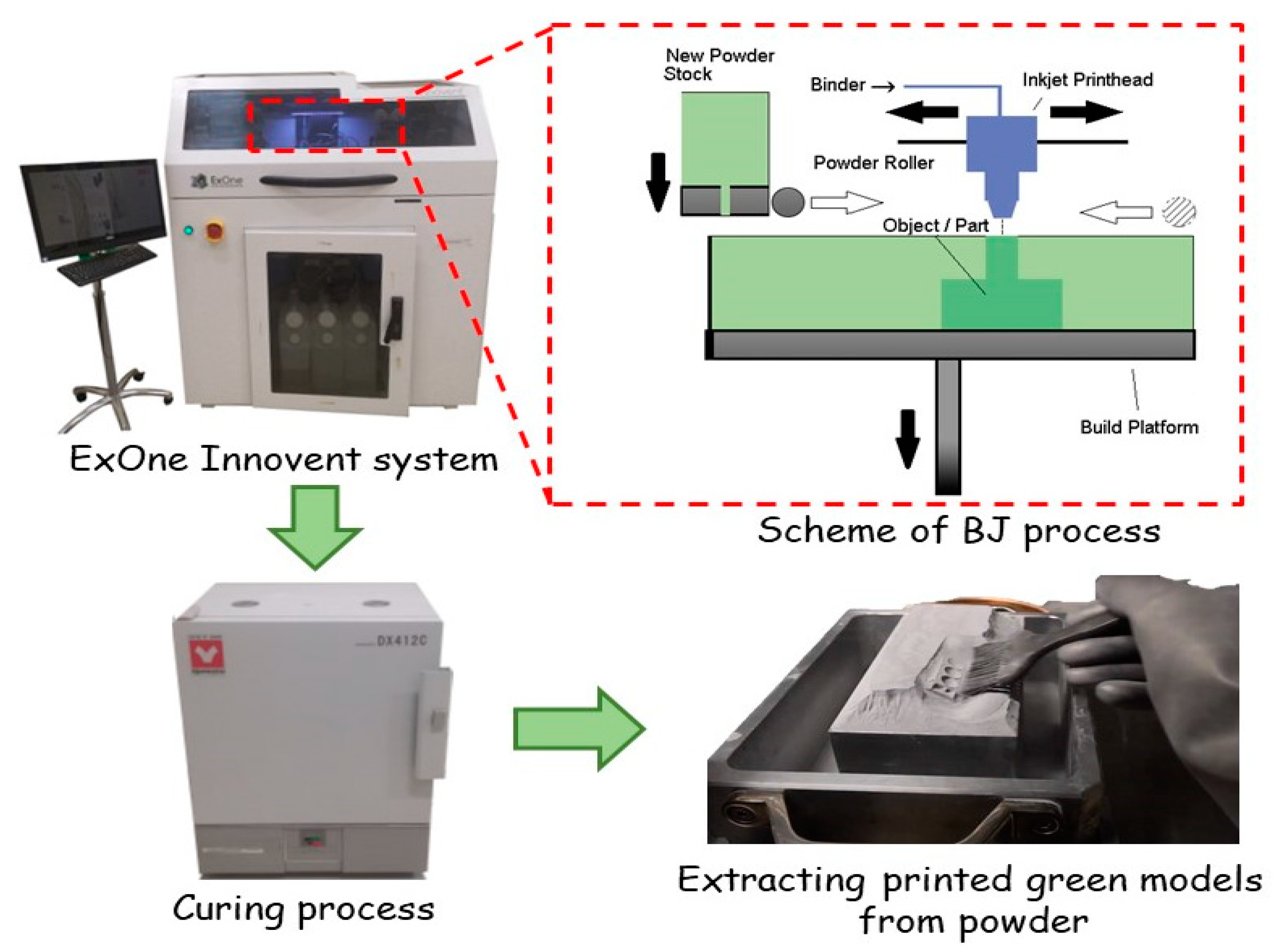
2.2. Fabrication
- A thin layer of powder material is formed on the platform using a roller;
- A liquid binder is selectively sprayed to the powder layer using a print head, in accordance with the cross-section of the computer model;
- Then the platform is lowered to a given thickness of one layer;
- The powder layer is dried and heated using an infrared heater;
- From the hopper, using an oscillator, the powder is fed to the surface of the platform and a new layer of powder is applied;
- Then the layer is leveled using a rotating roller;
- Processes 1–6 are repeated until a full-size green model is made.
2.3. Thermal Post-Treatment
2.4. Characterization
3. Results and Discussion
3.1. Investigation of Debinding Process
3.2. Binder Jetting Process
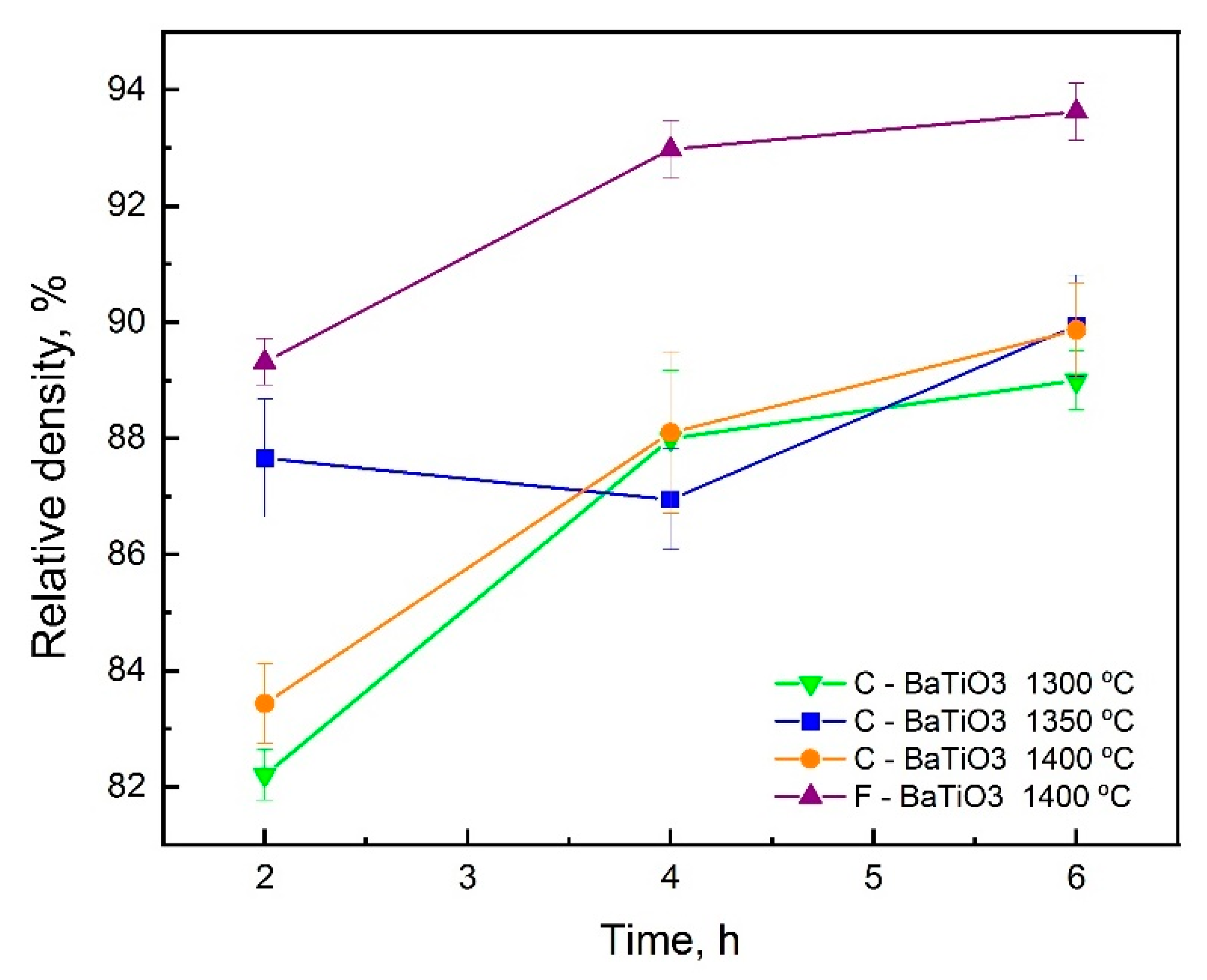
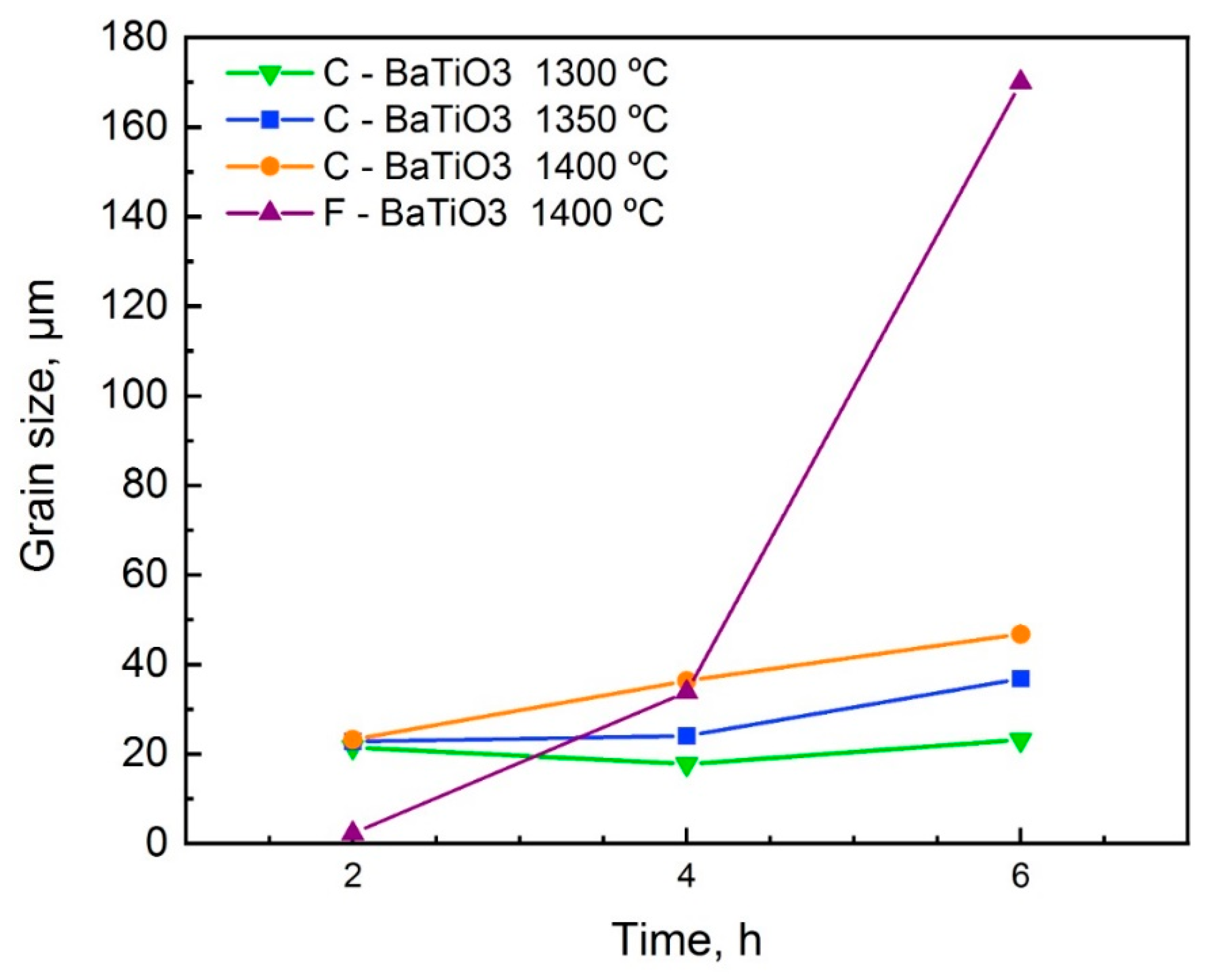
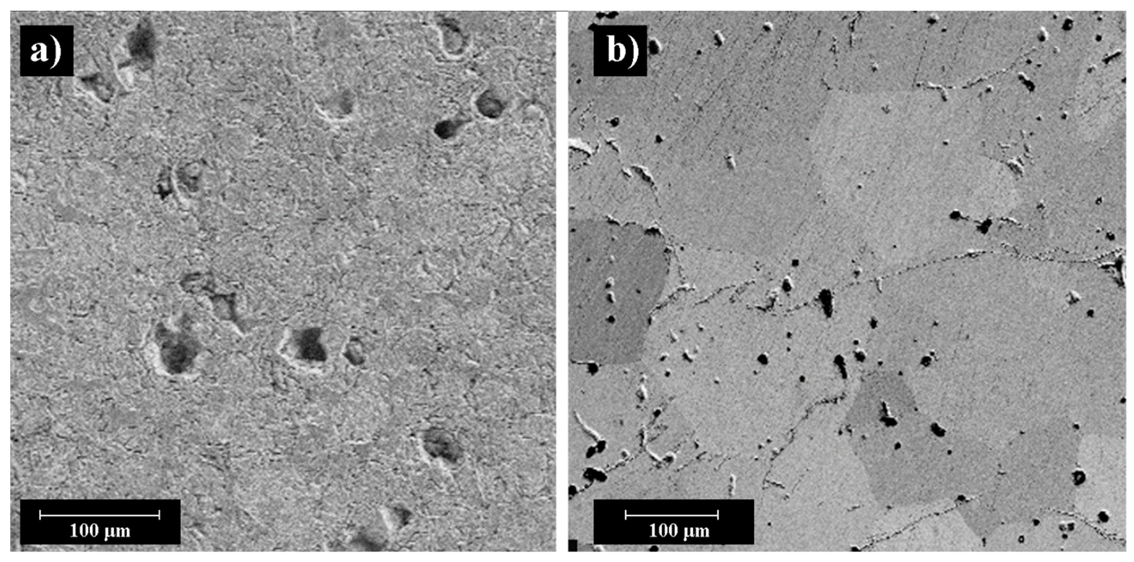
3.3. Investigation of Sintering Process, Shrinkage, Microstructure, Porosity
3.4. Investigation of Functional Properties
4. Conclusions
Author Contributions
Funding
Institutional Review Board Statement
Informed Consent Statement
Data Availability Statement
Conflicts of Interest
References
- Yin, Q.; Zhu, B.; Zeng, H. Microstructure, Property and Processing of Functional Ceramics; Springer: Berlin/Heidelberg, Germany, 2010; ISBN 3642016944. [Google Scholar]
- Mostafaei, A.; Elliott, A.M.; Barnes, J.E.; Cramer, C.L.; Nandwana, P.; Chmielus, M. Binder jet 3D printing—Process parameters, materials, properties, and challenges. Prog. Mater. Sci. 2020, 100684. [Google Scholar] [CrossRef]
- Eichel, R.-A.; Erünal, E.; Drahus, M.D.; Smyth, D.M.; van Tol, J.; Acker, J.; Kungl, H.; Hoffmann, M.J. Local variations in defect polarization and covalent bonding in ferroelectric Cu2+-doped PZT and KNN functional ceramics at the morphotropic phase boundary. Phys. Chem. Chem. Phys. 2009, 11, 8698–8705. [Google Scholar] [CrossRef]
- Lin, X.; Yuan, F.G. Diagnostic Lamb waves in an integrated piezoelectric sensor/actuator plate: Analytical and experimental studies. Smart Mater. Struct. 2001, 10, 907. [Google Scholar] [CrossRef]
- Chavez, L.A.; Jimenez, F.O.Z.; Wilburn, B.R.; Delfin, L.C.; Kim, H.; Love, N.; Lin, Y. Characterization of thermal energy harvesting using pyroelectric ceramics at elevated temperatures. Energy Harvest. Syst. 2018, 5, 3–10. [Google Scholar] [CrossRef][Green Version]
- Zhao, X.; Gao, H.; Zhang, G.; Ayhan, B.; Yan, F.; Kwan, C.; Rose, J.L. Active health monitoring of an aircraft wing with embedded piezoelectric sensor/actuator network: I. Defect detection, localization and growth monitoring. Smart Mater. Struct. 2007, 16, 1208. [Google Scholar] [CrossRef]
- Kim, H.; Torres, F.; Villagran, D.; Stewart, C.; Lin, Y.; Tseng, T.B. 3D printing of BaTiO3/PVDF composites with electric in situ poling for pressure sensor applications. Macromol. Mater. Eng. 2017, 302, 1700229. [Google Scholar] [CrossRef]
- Zhang, S.; Yu, F. Piezoelectric materials for high temperature sensors. J. Am. Ceram. Soc. 2011, 94, 3153–3170. [Google Scholar] [CrossRef]
- Chavez, L.A.; Elicerio, V.F.; Regis, J.E.; Kim, H.; Rosales, C.A.G.; Love, N.D.; Lin, Y. Thermal and mechanical energy har-vesting using piezoelectric ceramics. Mater. Res. Express 2018, 6, 25701. [Google Scholar] [CrossRef]
- Yonghong, L.; Zhixin, J.; Jinchun, L. Study on hole machining of non-conducting ceramics by gas-filled electrodischarge and electrochemical compound machining. J. Mater. Process. Technol. 1997, 69, 198–202. [Google Scholar] [CrossRef]
- Cook, R.F.; Freiman, S.W.; Lawn, B.R.; Pohanka, R.C. Fracture of ferroelectric ceramics. Ferroelectrics 1983, 50, 267–272. [Google Scholar] [CrossRef]
- Gao, W.; Zhang, Y.; Ramanujan, D.; Ramani, K.; Chen, Y.; Williams, C.B.; Wang, C.C.L.; Shin, Y.C.; Zhang, S.; Zavattieri, P.D. The status, challenges, and future of additive manufacturing in engineering. Comput. Des. 2015, 69, 65–89. [Google Scholar] [CrossRef]
- Salehi, M.; Gupta, M.; Maleksaeedi, S.; Sharon, N.M.L. Inkjet Based 3D Additive Manufacturing of Metals; Materials Research Forum LLC: Millersville, PA, USA, 2018. [Google Scholar]
- Xu, Y.; Wu, X.; Guo, X.; Kong, B.; Zhang, M.; Qian, X.; Mi, S.; Sun, W. The boom in 3D-printed sensor technology. Sensors 2017, 17, 1166. [Google Scholar] [CrossRef] [PubMed]
- Zhang, X.; Song, S.; Yao, M.J. Fabrication of embedded piezoelectric sensors and its application in traffic engineering. In Proceedings of the 2017 2nd IEEE International Conference on Intelligent Transportation Engineering (ICITE), Singapore, 1–3 September 2017; pp. 259–265. [Google Scholar]
- Bandyopadhyay, A.; Panda, R.K.; McNulty, T.F.; Mohammadi, F.; Danforth, S.C.; Safari, A. Piezoelectric ceramics and compo-sites via rapid prototyping techniques. Rapid Prototyp. J. 1998, 4, 37–49. [Google Scholar] [CrossRef]
- Smay, J.E.; Cesarano, J.; Lewis, J.A. Colloidal inks for directed assembly of 3-D periodic structures. Langmuir 2002, 18, 5429–5437. [Google Scholar] [CrossRef]
- Chen, Y.; Bao, X.; Wong, C.-M.; Cheng, J.; Wu, H.; Song, H.; Ji, X.; Wu, S. PZT ceramics fabricated based on stereolithography for an ultrasound transducer array application. Ceram. Int. 2018, 44, 22725–22730. [Google Scholar] [CrossRef]
- Cui, H.; Hensleigh, R.; Yao, D.; Maurya, D.; Kumar, P.; Kang, M.G.; Priya, S.; Zheng, X.R. Three-dimensional printing of piezoelectric materials with designed anisotropy and directional response. Nat. Mater. 2019, 18, 234–241. [Google Scholar] [CrossRef]
- Lejeune, M.; Chartier, T.; Dossou-Yovo, C.; Noguera, R. Ink-jet printing of ceramic micro-pillar arrays. J. Eur. Ceram. Soc. 2009, 29, 905–911. [Google Scholar] [CrossRef]
- Wan, C.; Bowen, C.R. Multiscale-structuring of polyvinylidene fluoride for energy harvesting: The impact of molecular-, micro-and macro-structure. J. Mater. Chem. A 2017, 5, 3091–3128. [Google Scholar] [CrossRef]
- Kim, H.; Renteria-Marquez, A.; Islam, M.D.; Chavez, L.A.; Garcia Rosales, C.A.; Ahsan, M.A. Fabrication of bulk piezoelectric and dielectric BaTiO3 ceramics using paste extrusion 3D printing technique. J. Am. Ceram. Soc. 2018, 102, 3685–3694. [Google Scholar] [CrossRef]
- Nadkarni, S.S.; Smay, J.E. Concentrated Barium Titanate Colloidal Gels Prepared by Bridging Flocculation for Use in Solid Freeform Fabrication. J. Am. Ceram. Soc. 2005, 89, 96–103. [Google Scholar] [CrossRef]
- Renteria, A.; Diaz, J.A.; He, B.; Renteria-Marquez, I.A.; Chavez, L.A.; Regis, J.E. Particle size influence on material properties of BaTiO3 ceramics fabricated using freeze-form extrusion 3D printing. Mater. Res. Express 2019, 6, 115211. [Google Scholar] [CrossRef]
- Rowlands, W.; Vaidhyanathan, B. Additive manufacturing of barium titanate based ceramic heaters with positive temperature coefficient of resistance (PTCR). J. Eur. Ceram. Soc. 2019, 39, 3475–3483. [Google Scholar] [CrossRef]
- Chen, Z.; Song, X.; Lei, L.; Chen, X.; Fei, C.; Chiu, C.T. 3D printing of piezoelectric element for energy focusing and ultrasonic sensing. Nano Energy 2016, 27, 78–86. [Google Scholar] [CrossRef]
- Cheng, J.; Chen, Y.; Wu, J.-W.; Ji, Z.-R.; Wu, S.-H. 3D Printing of BaTiO3 Piezoelectric Ceramics for a Focused Ultrasonic Array. Sensors 2019, 19, 4078. [Google Scholar] [CrossRef]
- Jang, J.H.; Wang, S.; Pilgrim, S.M.; Schulze, W.A. Preparation and characterization of barium titanate suspensions for stereolithography. J. Am. Ceram. Soc. 2000, 83, 1804–1806. [Google Scholar] [CrossRef]
- Kim, K.; Zhu, W.; Qu, X.; Aaronson, C.; McCall, W.R.; Chen, S. 3D optical printing of piezoelectric nanoparticle–polymer composite materials. ACS Nano 2014, 8, 9799–9806. [Google Scholar] [CrossRef] [PubMed]
- Sotov, A.; Kantyukov, A.; Popovich, A.; Sufiiarov, V. LCD-SLA 3D printing of BaTiO3 piezoelectric ceramics. Ceram Int. 2021. [Google Scholar] [CrossRef]
- Gaytan, S.M.; Cadena, M.A.; Karim, H.; Delfin, D.; Lin, Y.; Espalin, D.; MacDonald, E.; Wicker, R.B. Fabrication of barium titanate by binder jetting additive manufacturing technology. Ceram Int. 2015, 41, 6610–6619. [Google Scholar] [CrossRef]
- Chavez, L.A.; Wilburn, B.R.; Ibave, P.; Delfin, L.C.; Vargas, S.; Diaz, H.; Fulgentes, C.; Renteria, A.; Regis, J.; Liu, Y.; et al. Fabrication and characterization of 3D printing induced orthotropic functional ceramics. Smart Mater. Struct. 2019, 28, 125007. [Google Scholar] [CrossRef]
- Chavez, L.A.; Ibave, P.; Wilburn, B.; Alexander, D.; Stewart, C.; Wicker, R.; Lin, Y. The influence of printing parameters, post-processing, and testing conditions on the properties of binder jetting additive manufactured functional ceramics. Ceramics 2020, 3, 65–77. [Google Scholar] [CrossRef]
- Polley, C.; Distler, T.; Detsch, R.; Lund, H.; Springer, A.; Boccaccini, A.R.; Seitz, H. 3D printing of piezoelectric barium titanate-hydroxyapatite scaffolds with interconnected porosity for bone tissue engineering. Materials 2020, 13, 1773. [Google Scholar] [CrossRef] [PubMed]
- Chen, Z.; Yang, M.; Ji, M.; Kuang, X.; Qi, H.J.; Wang, T. Recyclable thermosetting polymers for digital light processing 3D printing. Mater. Des. 2021, 197, 109189. [Google Scholar] [CrossRef]
- Sufiiarov, V.; Polozov, I.; Kantykov, A.; Khaidorov, A. Binder jetting additive manufacturing of 420 stainless steel: Densification during sintering and effect of heat treatment on microstructure and hardness. Mater. Today Proc. 2020, 30, 592–595. [Google Scholar] [CrossRef]
- Polozov, I.; Sufiiarov, V.; Shamshurin, A. Synthesis of titanium orthorhombic alloy using binder jetting additive manufacturing. Mater. Lett. 2019, 243, 88–91. [Google Scholar] [CrossRef]
- Agapovichev, A.V.; Sotov, A.V.; Kokareva, V.V.; Smelov, V.G.; Kyarimov, R.R. Study of the structure and mechanical characteristics of samples obtained by selective laser melting technology from VT6 alloy metal powder. Nanosci. Technol. Int. J. 2017, 8, 323–330. [Google Scholar] [CrossRef]
- Sufiiarov, V.; Kantyukov, A.; Polozov, I. Reaction sintering of metal-ceramic AlSI-Al2O3 composites manufactured by binder jetting additive manufacturing process. In Proceedings of the METAL 2020—29th International Conference on Metallurgy and Materials, Brno, Czech Republic, 20–22 May 2020; pp. 1148–1155. [Google Scholar] [CrossRef]
- Do, T.; Kwon, P.; Shin, C.S. Process development toward full-density stainless steel parts with binder jetting printing. Int. J. Mach. Tools Manuf. 2017, 121, 50–60. [Google Scholar] [CrossRef]
- Acosta, M.; Novak, N.; Rojas, V.; Patel, S.; Vaish, R.; Koruza, J.; Rödel, J. BaTiO3-based piezoelectrics: Fundamentals, current status, and perspectives. Appl. Phys. Rev. 2017, 4, 041305. [Google Scholar] [CrossRef]


| Process Parameter | C-BaTiO3 Powder | F-BaTiO3 Powder |
|---|---|---|
| Recoating speed | 28 mm/s | 65 mm/s |
| Frequency of the oscillator | 5000 rpm | 4400 rpm |
| Layer thickness | 100 µm | 35 µm |
| Drying time | 25 s | 20 s |
| Drying temperature | 25 °C | 33 °C |
| Roller movement speed | 1 mm/s | 1 mm/s |
| Technology/Powder Type | έ | tgδ, % | kp | d33, pC/N |
|---|---|---|---|---|
| Binder Jetting/C-BaTiO3 | 750 | 5.53 | 0.15 | 118 |
| Traditional technology/C-BaTiO3 | 1872 | 7.9 | 0.22 | 163 |
| Binder Jetting/F-BaTiO3 | 811 | 11.59 | 0.19 | 183 |
| Traditional technology/F-BaTiO3 | 2367 | 1.7 | 0.36 | 230 |
Publisher’s Note: MDPI stays neutral with regard to jurisdictional claims in published maps and institutional affiliations. |
© 2021 by the authors. Licensee MDPI, Basel, Switzerland. This article is an open access article distributed under the terms and conditions of the Creative Commons Attribution (CC BY) license (https://creativecommons.org/licenses/by/4.0/).
Share and Cite
Sufiiarov, V.; Kantyukov, A.; Popovich, A.; Sotov, A. Structure and Properties of Barium Titanate Lead-Free Piezoceramic Manufactured by Binder Jetting Process. Materials 2021, 14, 4419. https://doi.org/10.3390/ma14164419
Sufiiarov V, Kantyukov A, Popovich A, Sotov A. Structure and Properties of Barium Titanate Lead-Free Piezoceramic Manufactured by Binder Jetting Process. Materials. 2021; 14(16):4419. https://doi.org/10.3390/ma14164419
Chicago/Turabian StyleSufiiarov, Vadim, Artem Kantyukov, Anatoliy Popovich, and Anton Sotov. 2021. "Structure and Properties of Barium Titanate Lead-Free Piezoceramic Manufactured by Binder Jetting Process" Materials 14, no. 16: 4419. https://doi.org/10.3390/ma14164419
APA StyleSufiiarov, V., Kantyukov, A., Popovich, A., & Sotov, A. (2021). Structure and Properties of Barium Titanate Lead-Free Piezoceramic Manufactured by Binder Jetting Process. Materials, 14(16), 4419. https://doi.org/10.3390/ma14164419