
Does Simulated Porcelain Firing Influence Corrosion Properties of Casted and Sintered CoCr Alloys?


Abstract
:1. Introduction
2. Materials and Methods
2.1. Sample Preparation
2.2. The Heat Treatment Simulating the Porcelain Firing
2.3. Sample Evaluation
2.3.1. SEM–EDS Study
2.3.2. Corrosion Examinations
3. Results
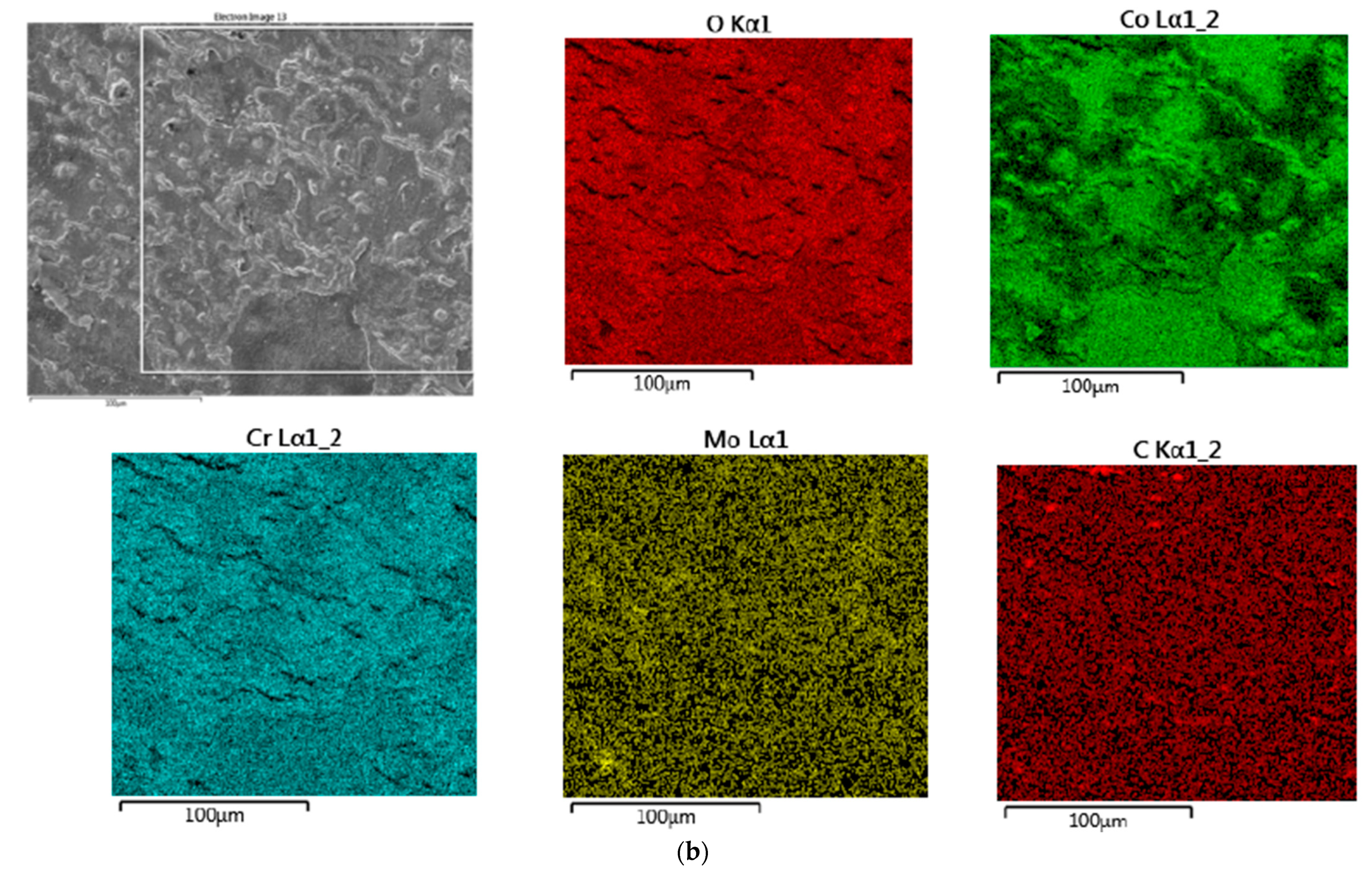
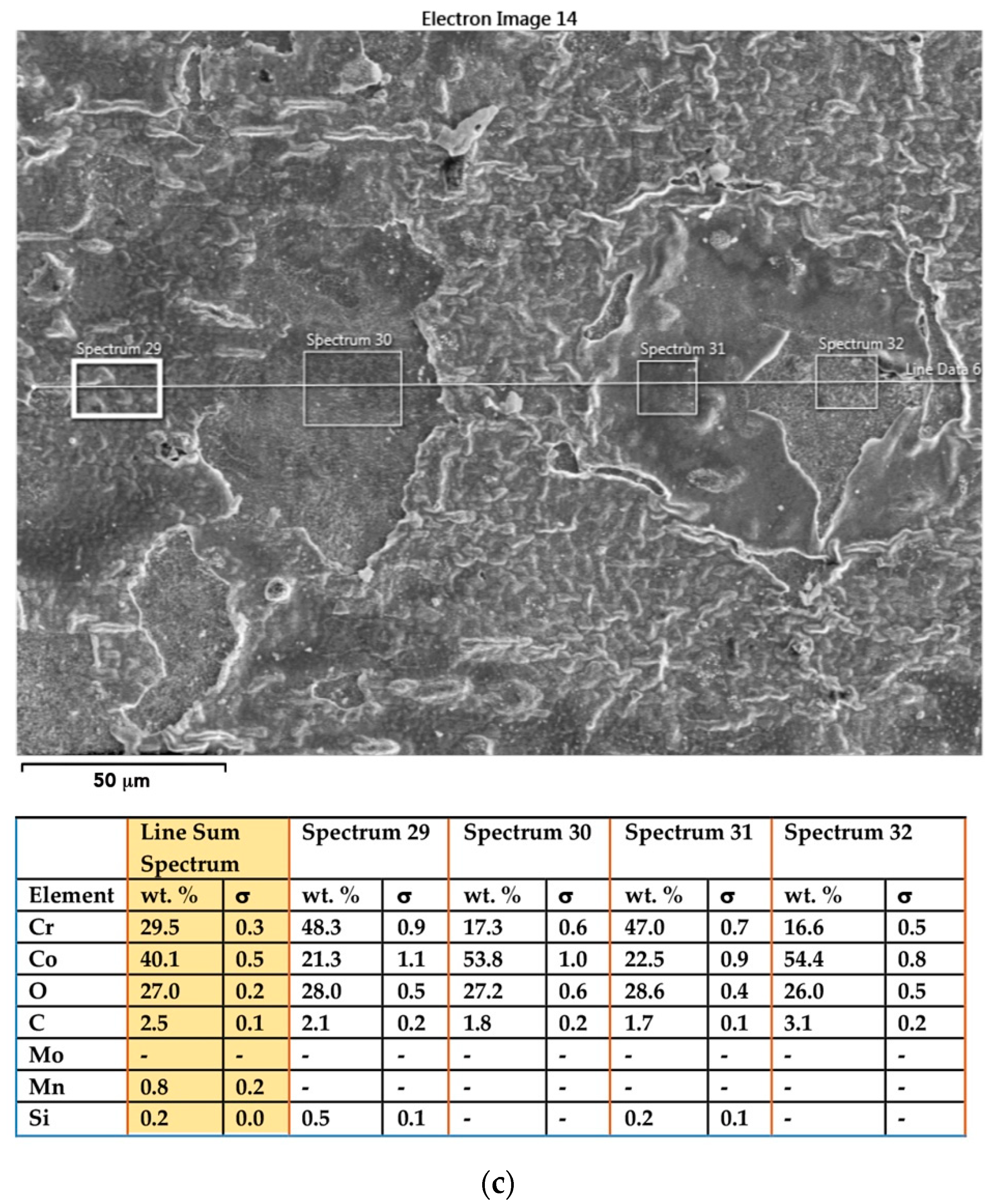
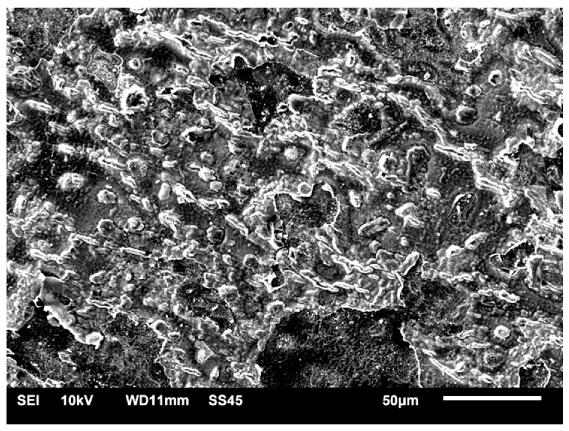
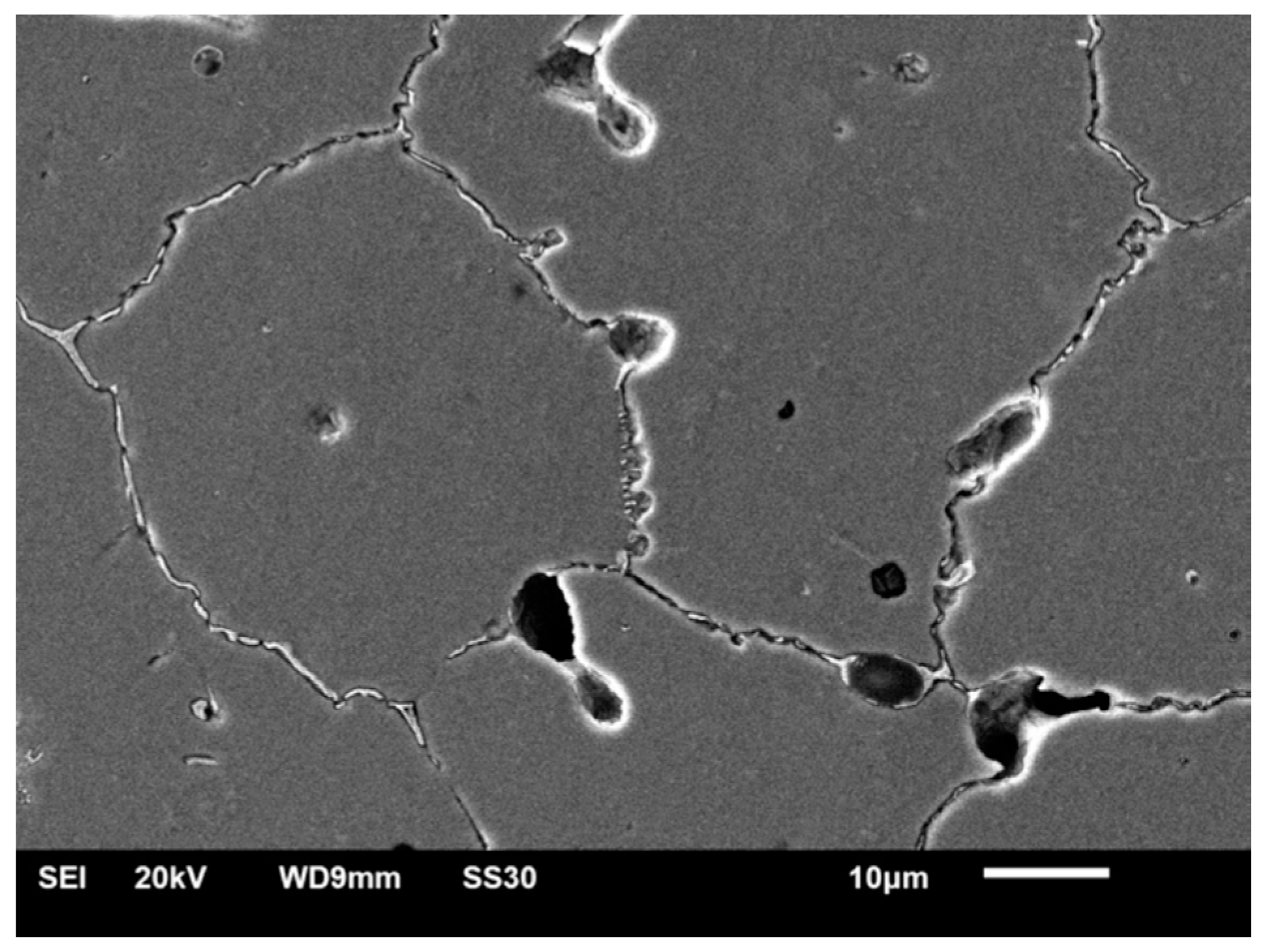
3.1. SEM–EDS Study
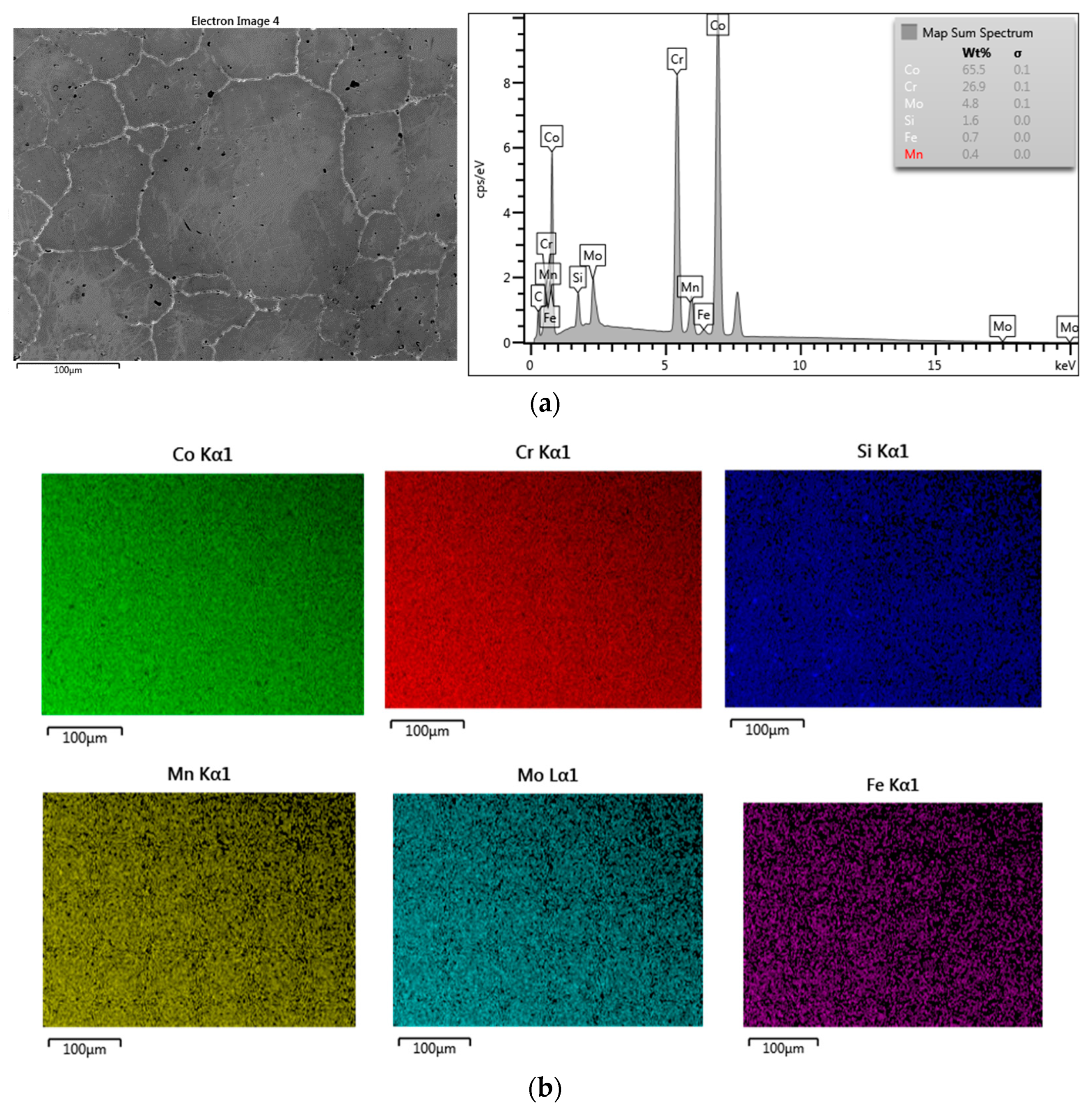
3.1.1. Samples without Heat Treatment and before Corrosion Examination
3.1.2. Samples after Heat Treatment and before the Corrosion Examination
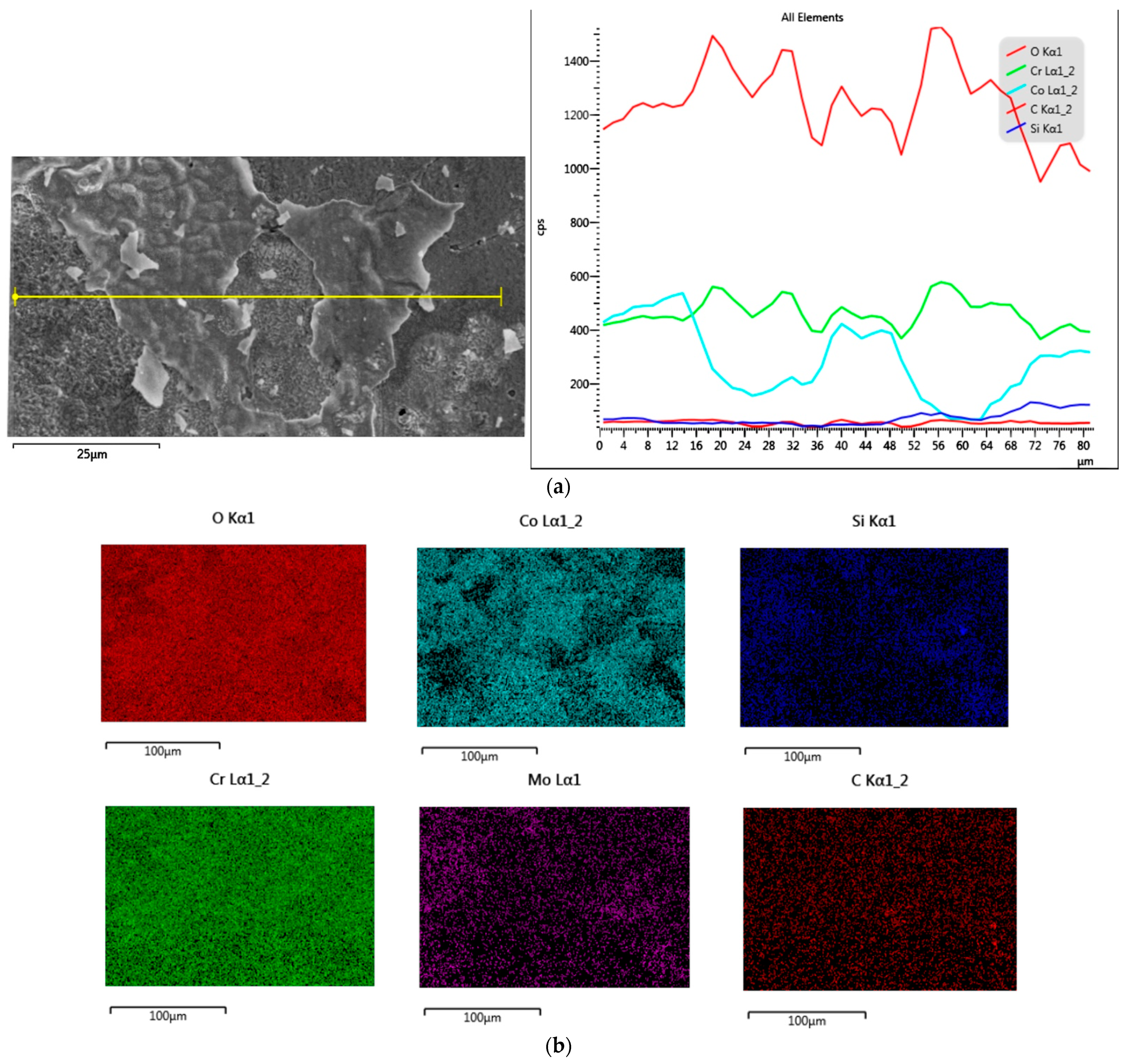
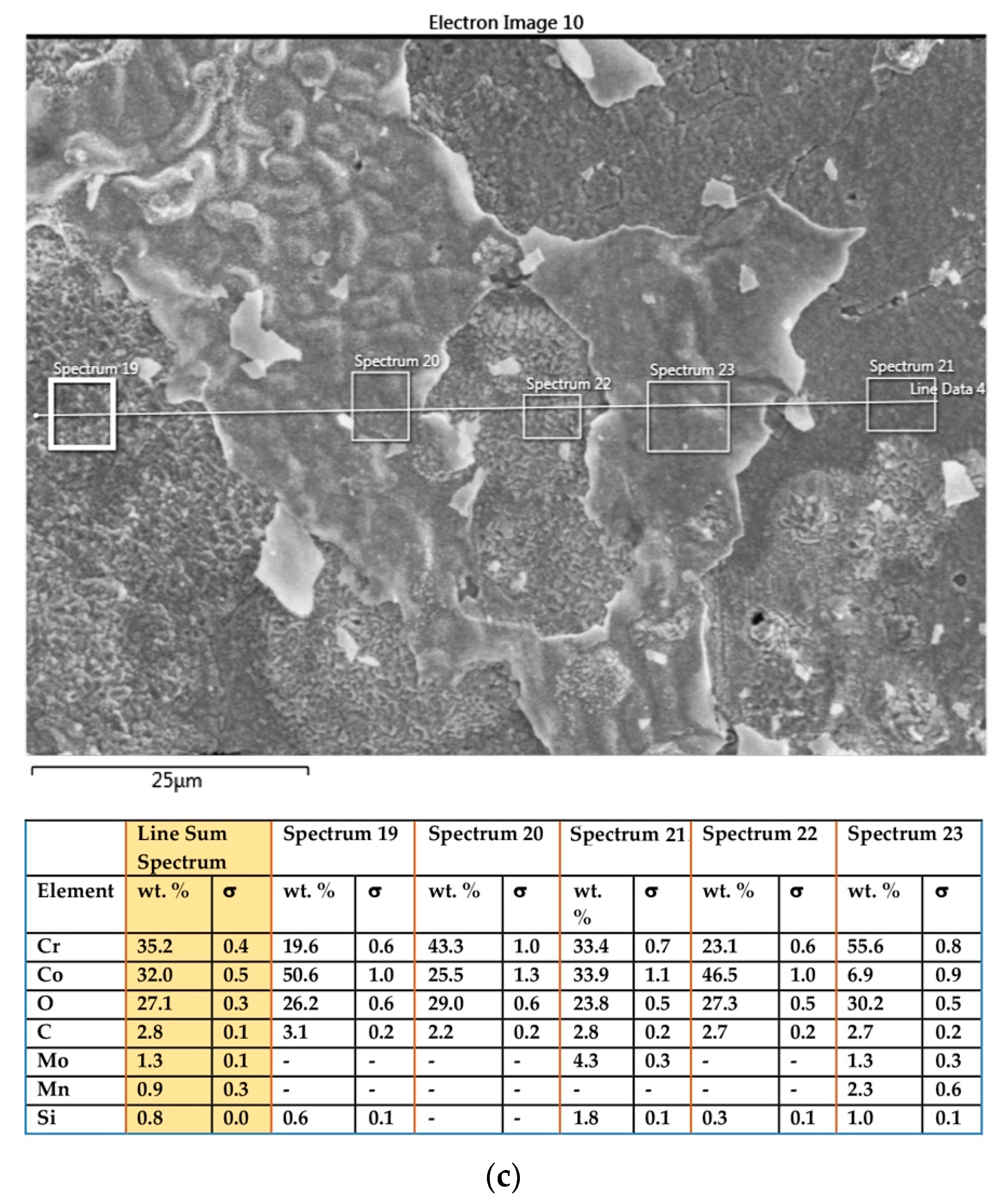
3.1.3. Samples before Heat Treatment and after the Corrosion Examination
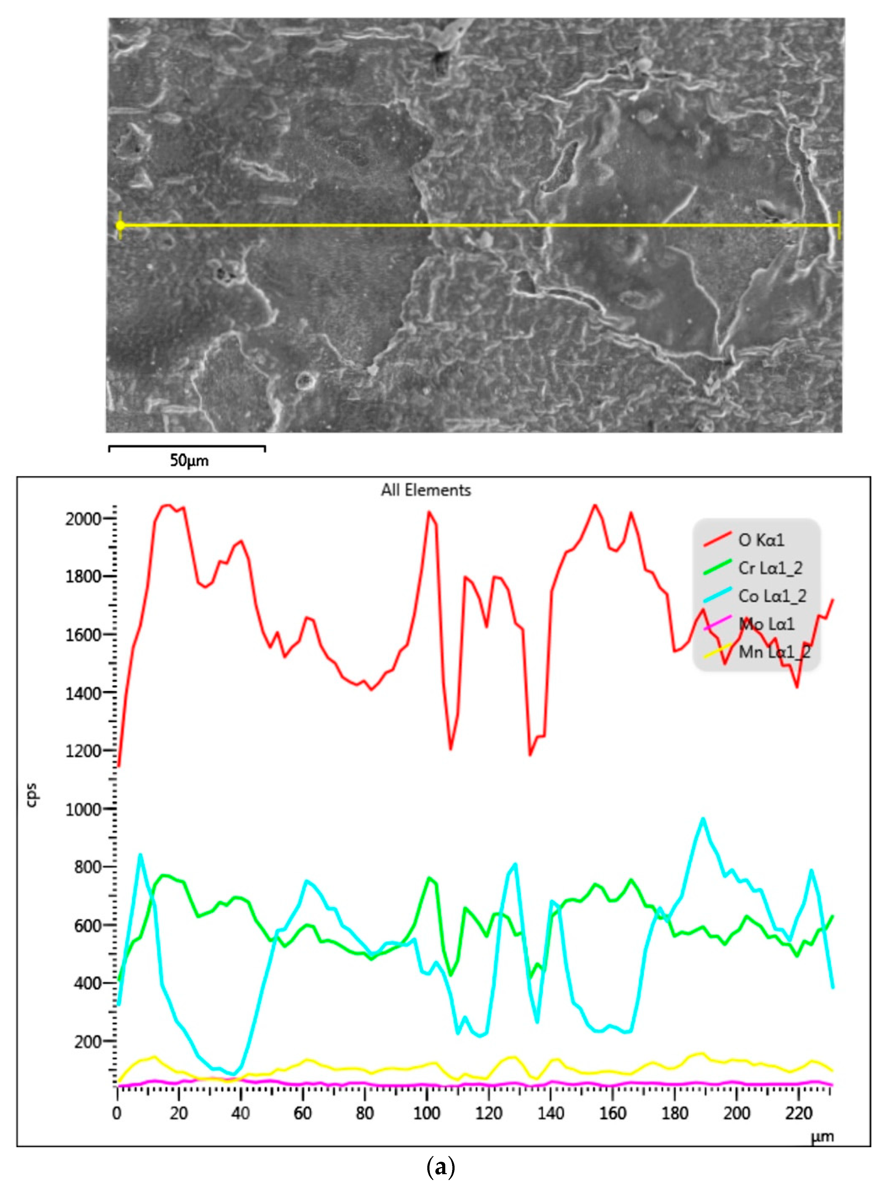
3.1.4. Samples after Heat Treatment and after the Corrosion Examination
3.2. Corrosion Examination
4. Discussion
5. Conclusions
- Thermal treatment (porcelain firing) did not cause chemical impurities formation on the surface of CoCr alloy.
- The sintered metal exhibited significantly higher corrosion resistance than the casted one due to its homogeneity of structure and chemical composition.
- Heat treatment (porcelain firing) decreased the resistance of the casted and sintered CoCr alloy to electrochemical corrosion. The reduction in corrosion resistance was significantly higher for the casted alloy than for the sintered alloy.
- The decrease in corrosion resistance might be due to an increased thickness and the heterogeneity of the oxide layers on the surface (especially for the casted alloy). The development of corrosion process started in the low-density areas of the oxide layers.
- The sintered metal seems to be a favourable framework material for porcelain fused to metal crowns.
Author Contributions
Funding
Institutional Review Board Statement
Informed Consent Statement
Data Availability Statement
Conflicts of Interest
References
- Elshahawy, W.; Watanabe, I.; Koike, M. Elemental ion release from four different fixed prosthodontic materials. Dent. Mater. Off. Publ. Acad. Dent. Mater. 2009, 25, 976–981. [Google Scholar] [CrossRef] [PubMed]
- Mareci, D.; Nemtoi, G.; Aelenei, N.; Bocanu, C. The electrochemical behaviour of various non-precious Ni and Co based alloys in artificial saliva. Eur. Cell. Mater. 2005, 10, 1–7, discussion 1–7. [Google Scholar] [PubMed]
- Reclaru, L.; Lüthy, H.; Eschler, P.-Y.; Blatter, A.; Susz, C. Corrosion behaviour of cobalt-chromium dental alloys doped with precious metals. Biomaterials 2005, 26, 4358–4365. [Google Scholar] [CrossRef]
- Viennot, S.; Dalard, F.; Lissac, M.; Grosgogeat, B. Corrosion resistance of cobalt-chromium and palladium-silver alloys used in fixed prosthetic restorations. Eur. J. Oral Sci. 2005, 117, 76–85. [Google Scholar] [CrossRef] [PubMed]
- Tuncdemir, A.R.; Karahan, I.; Polat, S.; Malkoc, M.A.; Dalkiz, M. The effect of repeated porcelain firings on corrosion resistance of different dental alloys. J. Adv. Prosthodont. 2013, 5, 44–50. [Google Scholar] [CrossRef] [PubMed] [Green Version]
- Johnson, T.; van Noort, R.; Stokes, C.W. Surface analysis of porcelain fused to metal systems. Dent. Mater. 2006, 22, 330–337. [Google Scholar] [CrossRef]
- Dobrzański, L.A.; Reimann, L. Influence of Cr and Co on hardness and corrosion resistance CoCrMo alloys used on dentures. J. Achiev. Mater. Manuf. Eng. 2011, 49, 193–199. [Google Scholar]
- Galo, R.; Ribeiro, R.; Rodrigues, R.; Rocha, L.; de Mattos Mda, G. Effects of chemical composition on the corrosion behavior of A7N01S-T5 Al alloys. Braz. Dent. J. 2012, 23, 141–148. [Google Scholar] [CrossRef] [Green Version]
- Bauer, S.; Schmuki, P.; von der Mark, K.; Park, J. Engineering biocompatible implant surfaces: Part I: Materials and surfaces. Prog. Mater. Sci. 2013, 58, 261–326. [Google Scholar] [CrossRef]
- Rylska, D.; Szynkowska, M.I.; Leśniewska, E.; Pawlaczyk, A.; Paryjczak, T.; Sokołowski, K.; Sokołowski, G.; Sokołowski, J. Analiza powierzchni biomateriałów metalicznych stosowanych w protetyce stomatologicznej wytwarzanych metodą frezowania. Przem. Chem. 2012, 91, 941–948. [Google Scholar]
- Choi, Y.-J.; Koak, J.-Y.; Heo, S.-J.; Kim, S.-K.; Ahn, J.-S.; Park, D.-S. Comparison of the mechanical properties and microstructures of fractured surface for Co-Cr alloy fabricated by conventional cast, 3-D printing laser-sintered and CAD/CAM milled techniques. J. Korean Acad. Prosthodont. 2014, 52, 67. [Google Scholar] [CrossRef] [Green Version]
- Geis-Gerstorfer, J.; Schille, C.; Schweizer, E. CoCr sinter alloy vs. CoCr casting alloy. Dent. Dialogue 2013, 14, 20–28. [Google Scholar]
- Schille, C.; Schweizer, E.; Geis-Gerstorfer, J. Corrosion behavior of dental CoCr alloys made by different digital workflow processes compared to cast CoCr alloys. J. Med. Mater. Technol. 2017, 1, 1–4. [Google Scholar] [CrossRef]
- De Freitas, B.X.; Nunes, C.A.; dos Santos, C. Sintering behaviour of Co-28%Cr-6%Mo compacted blocks for dental prosthesis. J. Mater. Res. Technol. 2019, 8, 2052–2062. [Google Scholar] [CrossRef]
- Hama Suleiman, S.; Vult Von Steyern, P. Fracture strength of porcelain fused to metal crowns made of cast, milled or laser-sintered cobalt-chromium. Acta Odontol. Scand. 2013, 71, 1280–1289. [Google Scholar] [CrossRef] [PubMed]
- Tuna, S.; Özçiçek Pekmez, N.; Kürkçüoğlu, I. Corrosion resistance assessment of Co-Cr alloy frameworks fabricated by CAD/CAM milling, laser sintering, and casting methods. J. Prosthet. Dent. 2015, 114, 725–734. [Google Scholar] [CrossRef] [PubMed]
- Xin, X.; Chen, J.; Xiang, N.; Wei, B. Surface properties and corrosion behavior of Co-Cr alloy fabricated with selective laser melting technique. Cell Biochem. Biophys. 2013, 67, 983–990. [Google Scholar] [CrossRef]
- Xin, X.; Chen, J.; Xiang, N.; Gong, Y.; Wei, B. Surface characteristics and corrosion properties of selective laser melted Co-Cr dental alloy after porcelain firing. Dent. Mater. 2014, 30, 263–270. [Google Scholar] [CrossRef] [PubMed]
- Han, X.; Sawada, T.; Schille, C.; Schweizer, E.; Scheideler, L.; Geis-Gerstorfer, J.; Rupp, F.; Spintzyk, S. Comparative analysis of mechanical properties and metal-ceramic bond strength of Co-Cr dental alloy fabricated by different manufacturing processes. Materials 2018, 11, 1801. [Google Scholar] [CrossRef] [Green Version]
- Mengucci, P.; Barucca, G.; Gatto, A.; Bassoli, E.; Denti, L.; Fiori, F.; Girardin, E.; Bastianoni, P.; Rutkowski, B.; Czyrska-Filemonowicz, A. Effects of thermal treatments on microstructure and mechanical properties of a Co-Cr-Mo-W biomedical alloy produced by laser sintering. J. Mech. Behav. Biomed. Mater. 2016, 60, 106–117. [Google Scholar] [CrossRef]
- Wei, W.; Zhou, Y.; Sun, Q.; Li, N.; Yan, J.; Li, H.; Liu, W.; Huang, C. Microstructures and Mechanical Properties of Dental Co-Cr-Mo-W Alloys Fabricated by Selective Laser Melting at Different Subsequent Heat Treatment Temperatures. Metall. Mater. Trans. A 2020, 51, 3205–3214. [Google Scholar] [CrossRef]
- Krug, K.-P.; Knauber, A.W.; Nothdurft, F.P. Fracture behavior of metal-ceramic fixed dental prostheses with frameworks from cast or a newly developed sintered cobalt-chromium alloy. Clin. Oral Investig. 2015, 19, 401–411. [Google Scholar] [CrossRef]
- Sembiring, N.P.; Tamin, H.Z.; Nasution, M.I. Effect of Temperature and Number of Opaque Porcelain Firing on Bond Strength of Metal-Ceramic Fixed Partial Denture. IOSR J. Dent. Med. Sci. 2017, 16, 20–25. [Google Scholar] [CrossRef]
- Koutsoukis, T.; Zinelis, S.; Eliades, G.; Al-Wazzan, K.; Al Rifaiy, M.; Al Jabbari, Y.S. Selective Laser Melting Technique of Co-Cr Dental Alloys: A Review of Structure and Properties and Comparative Analysis with Other Available Techniques. J. Prosthodont. 2015, 24, 303–312. [Google Scholar] [CrossRef] [PubMed]
- Yamanaka, K.; Mori, M.; Chiba, A. Surface characterisation of Ni-free Co–Cr–W-based dental alloys exposed to high temperatures and the effects of adding silicon. Corros. Sci. 2015, 94, 411–419. [Google Scholar] [CrossRef]
- Li, J.; Ye, X.; Li, B.; Liao, J.; Zhuang, P.; Ye, J. Effect of oxidation heat treatment on the bond strength between a ceramic and cast and milled cobalt–chromium alloys. Eur. J. Oral Sci. 2015, 123, 297–304. [Google Scholar] [CrossRef] [PubMed]
- Li, J.; Chen, C.; Liao, J.; Liu, L.; Ye, X.; Lin, S.; Ye, J. Bond strengths of porcelain to cobalt-chromium alloys made by casting, milling, and selective laser melting. J. Prosthet. Dent. 2017, 118, 69–75. [Google Scholar] [CrossRef]
- Armstrong, S.; Geraldeli, S.; Maia, R.; Raposo, L.H.A.; Soares, C.J.; Yamagawa, J. Adhesion to tooth structure: A critical review of “micro” bond strength test methods. Dent. Mater. 2010, 26, e50–e62. [Google Scholar] [CrossRef]
- Bumgardner, J.D.; Lucas, L.C. Surface analysis of nickel-chromium dental alloys. Dent. Mater. 1993, 9, 252–259. [Google Scholar] [CrossRef]
- Lin, H.-Y.; Bowers, B.; Wolan, J.T.; Cai, Z.; Bumgardner, J.D. Metallurgical, surface, and corrosion analysis of Ni-Cr dental casting alloys before and after porcelain firing. Dent. Mater. 2008, 24, 378–385. [Google Scholar] [CrossRef]
- Chen, L.; Cai, H.; Xu, G.; Fang, C. Effect of porcelain firing cycle on microstructure and corrosion resistance of 4 metal ceramic alloys. Zhong Nan Da Xue Xue Bao Yi Xue Ban J. Cent. South Univ. Med. Sci. 2006, 31, 408–410. [Google Scholar]
- Qiu, J.; Yu, W.-Q.; Zhang, F.-Q.; Smales, R.J.; Zhang, Y.-L.; Lu, C.-H. Corrosion behaviour and surface analysis of a Co-Cr and two Ni-Cr dental alloys before and after simulated porcelain firing. Eur. J. Oral Sci. 2011, 119, 93–101. [Google Scholar] [CrossRef] [PubMed]
- Kajima, Y.; Takaichi, A.; Kittikundecha, N.; Nakamoto, T.; Kimura, T.; Nomura, N.; Kawasaki, A.; Hanawa, T.; Takahashi, H.; Wakabayashi, N. Effect of heat-treatment temperature on microstructures and mechanical properties of Co–Cr–Mo alloys fabricated by selective laser melting. Mater. Sci. Eng. A 2018, 726, 21–31. [Google Scholar] [CrossRef]
- Farzin, M.; Giti, R.; Asalforush-Rezaiye, A. The effect of multiple firings on the shear bond strength of porcelain to a new millable alloy and a conventional casting alloy. Materials 2018, 11, 478. [Google Scholar] [CrossRef] [Green Version]
- Hong, J.T.; Shin, S.Y. A comparative study on the bond strength of porcelain to the millingable Pd-Ag alloy. J. Adv. Prosthodont. 2014, 6, 372–378. [Google Scholar] [CrossRef] [Green Version]
- Stawarczyk, B.; Eichberger, M.; Hoffmann, R.; Noack, F.; Schweiger, J.; Edelhoff, D.; Beuer, F. A novel CAD/CAM base metal compared to conventional CoCrMo alloys: An in-vitro study of the long-term metal-ceramic bond strength. Oral Health Dent. Manag. 2014, 13, 446–452. [Google Scholar] [CrossRef]
- Park, J.K.; Kim, H.Y.; Kim, W.C.; Kim, J.H. Evaluation of the fit of metal ceramic restorations fabricated with a pre-sintered soft alloy. J. Prosthet. Dent. 2016, 116, 909–915. [Google Scholar] [CrossRef]
- Rylska, D.; Sokołowski, G.; Konieczny, B.; Sokołowski, J. The structure and corrosive properties of the CoCr-base dental alloy obtained by soft material milling followed by sinterization. J. Achiev. Mater. Manuf. Eng. 2016, 74, 60–71. [Google Scholar] [CrossRef]
- Kim, H.R.; Kim, Y.K.; Son, J.S.; Min, B.K.; Kim, K.-H.; Kwon, T.-Y. Comparison of in vitro biocompatibility of a Co–Cr dental alloy produced by new milling/post-sintering or traditional casting technique. Mater. Lett. 2016, 178, 300–303. [Google Scholar] [CrossRef]
- Al Jabbari, Y.S.; Barmpagadaki, X.; Psarris, I.; Zinelis, S. Microstructural, mechanical, ionic release and tarnish resistance characterization of porcelain fused to metal Co–Cr alloys manufactured via casting and three different CAD/CAM techniques. J. Prosthodont. Res. 2019, 63, 150–156. [Google Scholar] [CrossRef]
- Frankel, G.S. Pitting Corrosion. In Corrosion: Fundamentals, Testing, and Protection; ASM International: Russell Township, OH, USA, 2003; ISBN 978-1-62708-182-5. [Google Scholar]
- Baboian, R.; Haynes, G.S.; International, A.; Materials, A.S. Cyclic Polarization Measurements—Experimental Procedure and Evaluation of Test. Data; ASTM International: West Conshohocken, PA, USA, 1981. [Google Scholar]
- Scully, J.; Budiansky, N.; Tiwary, Y.; Mikhailov, A.; Hudson, J.L. An alternate explanation for the abrupt current increase at the pitting potential. Corros. Sci. 2008, 50, 316–324. [Google Scholar] [CrossRef]
- Li, K.C.; Prior, D.J.; Waddell, J.N.; Swain, M. V Comparison of the microstructure and phase stability of as-cast, CAD/CAM and powder metallurgy manufactured Co-Cr dental alloys. Dent. Mater. 2015, 31, e306–e315. [Google Scholar] [CrossRef]
- Rylska, D.; Januszewicz, B.; Sokołowski, G.; Sokołowski, J. Corrosion resistance of Cr–Co alloys subjected to porcelain firing heat treatment—in vitro study. Processes 2021, 9, 636. [Google Scholar] [CrossRef]
- Eliaz, N. Corrosion of metallic biomaterials: A review. Materials 2019, 12, 407. [Google Scholar] [CrossRef] [Green Version]
- Pourzal, R.; Hall, D.J.; Ehrich, J.; McCarthy, S.M.; Mathew, M.T.; Jacobs, J.J.; Urban, R.M. Alloy Microstructure Dictates Corrosion Modes in THA Modular Junctions. Clin. Orthop. Relat. Res. 2017, 475, 3026–3043. [Google Scholar] [CrossRef] [Green Version]
- Panigrahi, P.; Liao, Y.; Mathew, M.T.; Fischer, A.; Wimmer, M.A.; Jacobs, J.J.; Marks, L.D. Intergranular pitting corrosion of CoCrMo biomedical implant alloy. J. Biomed. Mater. Res. Part B Appl. Biomater. 2014, 102, 850–859. [Google Scholar] [CrossRef] [PubMed]
- Stemmer, P.; Pourzal, R.; Liao, Y.; Marks, L.; Morlock, M.; Jacobs, J.J.; Wimmer, M.A.; Fischer, A.; Fischer, A. Microstructure of retrievals made from standard cast HC-CoCrMo alloys. In Metal-On-Metal Total Hip Replacement Devices; Kurtz, S., Greenwald, A., Mihalko, W., Lemons, J., Eds.; ASTM International: West Conshohocken, PA, USA, 2013; pp. 251–267. ISBN 978-0-8031-7572-3. [Google Scholar]
- Ardlin, B.I.; Dahl, J.E.; Tibballs, J.E. Static immersion and irritation tests of dental metal-ceramic alloys. Eur. J. Oral Sci. 2005, 113, 83–89. [Google Scholar] [CrossRef] [PubMed]
- Roach, M.D.; Wolan, J.T.; Parsell, D.E.; Bumgardner, J.D. Use of x-ray photoelectron spectroscopy and cyclic polarization to evaluate the corrosion behavior of six nickel-chromium alloys before and after porcelain-fused-to-metal firing. J. Prosthet. Dent. 2000, 84, 623–634. [Google Scholar] [CrossRef] [PubMed]
- Dave, V.; Kotian, R.; Madhyastha, P.; Boaz, K.; Rao, P.; Charitha, B.P. Simulated porcelain firing of Co-Cr Alloy. Iran. J. Mater. Sci. Eng. 2019, 16, 36–42. [Google Scholar] [CrossRef]
- Ashrafizadeh, A.; Ashrafizadeh, F. Structural features and corrosion analysis of thermally oxidized titanium. J. Alloys Compd. 2009, 480, 849–852. [Google Scholar] [CrossRef]
- Geurtsen, W. Biocompatibility of dental casting alloys. Crit. Rev. Oral Biol. Med. 1997, 13, 71–84. [Google Scholar] [CrossRef] [PubMed] [Green Version]
- Huang, H.-H. Effect of chemical composition on the corrosion behavior of Ni-Cr-Mo dental alloys. J. Biomed. Mater. Res. 2002, 60, 458–465. [Google Scholar] [CrossRef]


| Material | Company (Country) | Method | Co | Cr | Mo | Si | Mn | Other Elements |
|---|---|---|---|---|---|---|---|---|
| Soft Metal | LHK (Jicheon-myeon, Korea) | MSM | 63.4 | 29 | 5.8 | max 1 | - | <1% |
| MoguCera C | Scheftner (Mainz, Germany) | casting | 65 | 28 | 5 | Si + C < 1% | 1 | - |
| Sample Material | Soft-Metal (SM) | MoguCera C (CM) | ||
|---|---|---|---|---|
| Manufacturing method | milling in soft material + sintering | casting | ||
| Heat treatment | - | + | - | + |
| Study groups | SM-Control (n = 3) | SM-HT (n = 3) | MC-Control (n = 3) | MC-HT (n = 3) |
| Evaluation | SEM–EDS | |||
| Corrosion examinations (Ecorr, jcorr, polarization curve, Ebr) | ||||
| Study groups | SM-Control-Corr (n = 3) | SM-HT-Corr (n = 3) | MC-Control-Corr (n = 3) | MC-HT-Corr (n = 3) |
| Evaluation | SEM | |||
| Type of Porcelain Material | Opaquer | Dentin | Glaze |
|---|---|---|---|
| Initial temperature B (°C) | 400 | 600 | 650 |
| Time for drying and furnace chamber closing S (min) | 8 | 7 | 5 |
| Speed of temperature’s increase t1 (°C/min) | 65 | 45 | 50 |
| Firing temperature T (°C) | 1000 | 940 | 910 |
| Warming up time H (min) | 1 | - | - |
| Temperature of vacuum activation V1 (°C) | 400 | 600 | - |
| Temperature of vacuum deactivation V2 (°C) | 1000 | 930 | - |
| Sample | Sample Number | jcorr 10−6 [A/cm2] | Ecorr [mV] |
|---|---|---|---|
| MC-Control | I | 5.012 | −367.11 |
| II | 4.954 | −359.86 | |
| III | 5.032 | −374.23 | |
| Average value | 4.999 ± 0.041 | −367.07 ± 7.18 | |
| SM-Control | I | 0.943 | −185.31 |
| II | 0.932 | −188.12 | |
| III | 0.975 | −179.46 | |
| Average value | 0.950 ± 0.022 | −184.30 ± 4.42 |
| Sample | Sample Number | jcorr 10−6 [A/cm2] | Ecorr [mV] |
|---|---|---|---|
| MC-HT | I | 8.977 | −389.39 |
| II | 9.021 | −387.41 | |
| III | 9.074 | −385.88 | |
| Average value | 9.024 ± 0.049 | −387.56 ± 1.76 | |
| SM-HT | I | 1.023 | −199.1 |
| II | 1.034 | −201.17 | |
| III | 1.046 | −199.47 | |
| Average value | 1.034 ± 0.011 | −199.91 ± 1.10 |
Publisher’s Note: MDPI stays neutral with regard to jurisdictional claims in published maps and institutional affiliations. |
© 2021 by the authors. Licensee MDPI, Basel, Switzerland. This article is an open access article distributed under the terms and conditions of the Creative Commons Attribution (CC BY) license (https://creativecommons.org/licenses/by/4.0/).
Share and Cite
Rylska, D.; Sokolowski, G.; Lukomska-Szymanska, M. Does Simulated Porcelain Firing Influence Corrosion Properties of Casted and Sintered CoCr Alloys? Materials 2021, 14, 4147. https://doi.org/10.3390/ma14154147
Rylska D, Sokolowski G, Lukomska-Szymanska M. Does Simulated Porcelain Firing Influence Corrosion Properties of Casted and Sintered CoCr Alloys? Materials. 2021; 14(15):4147. https://doi.org/10.3390/ma14154147
Chicago/Turabian StyleRylska, Dorota, Grzegorz Sokolowski, and Monika Lukomska-Szymanska. 2021. "Does Simulated Porcelain Firing Influence Corrosion Properties of Casted and Sintered CoCr Alloys?" Materials 14, no. 15: 4147. https://doi.org/10.3390/ma14154147
APA StyleRylska, D., Sokolowski, G., & Lukomska-Szymanska, M. (2021). Does Simulated Porcelain Firing Influence Corrosion Properties of Casted and Sintered CoCr Alloys? Materials, 14(15), 4147. https://doi.org/10.3390/ma14154147