
Insight into the Mechanical Performance of the UHPC Repaired Cementitious Composite System after Exposure to High Temperatures


Abstract
:1. Introduction
2. Materials and Sample Preparation
2.1. Materials
2.2. Sample Preparation
3. Experimental Program and Methods
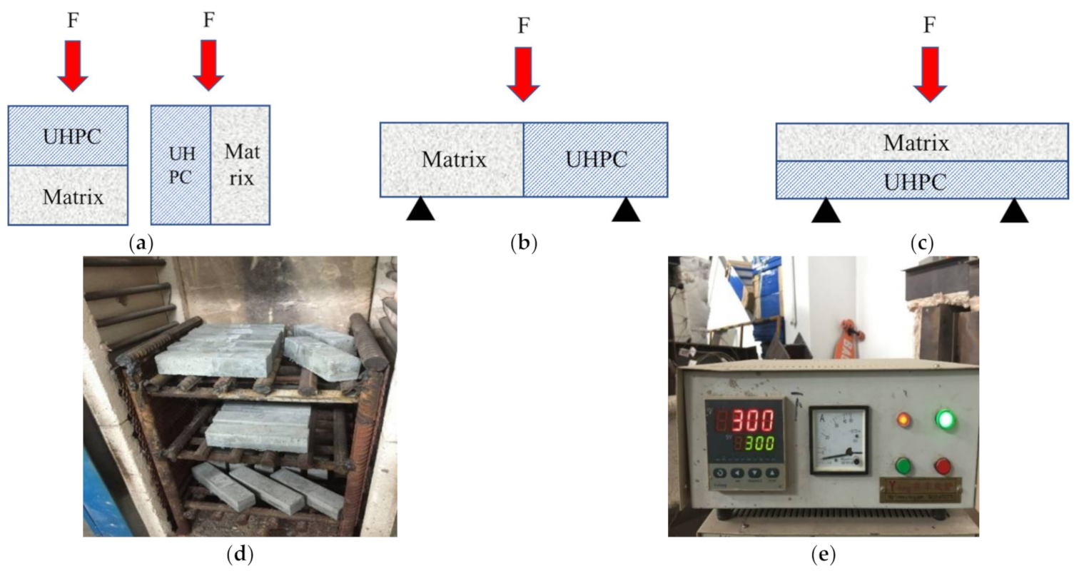
- High-temperature processing: It was carried out in a high-temperature furnace, as Figure 1d,e shows. The bonded systems were evenly placed in the high-temperature furnace, and the test temperatures were 100 °C (T2), 300 °C (T3), and 500 °C (T4). The heating rate was 5 °C/min. The target temperature was kept for half an hour. The specimens were taken out for subsequent testing when the temperature reduced to 20 °C. Based on the ISO 834 or ASTM E119 tests [24,25], the temperature experienced on the surface of cement-based composites may reach around 1200 °C. However, the temperature experienced within the bulk of the material—which is likely govern the performance of the structure—is typically notably smaller (below 1000 °C), based on its distance from the surface [26,27]. The thickness of the repair system is generally larger than 50 mm, at which point the temperature in the concrete specimen after 2 h in a fire was around 500 °C. Meanwhile, the thermal damage of concrete or fiber reinforced cementitious composites subjected to 500 °C was between 0.5 and 0.7 [28], which suggests the main degradation stage occurs at 500 °C. For these reasons, herein, the maximum temperature of 500 °C was employed.
- Physical properties tests: The mass change was measured before and after the high-temperature test. Three specimens were tested as one group. Appearance change and explosive spalling property were recorded during the whole process.
- Compressive strength tests: Bairoe electronic universal testing machine (Shanghai, China) was used to test the compressive strength, and the loading rate was 0.5 MPa/s. Two compression modes were adopted, i.e., the compression direction was parallel or perpendicular to the bonding surface (abbreviated as ∥ or ⊥).
- Bonding/flexural strength tests: Three-point bending tests were carried out by an electronic universal testing machine controlled by a SANS microcomputer (Bairoe company, Shanghai, China), and its loading rate was 0.08 mm/min. In flexural tests, the mid-span deflection was read by an electronic extensometer (Central iron & steel research institute, Beijing, China) and the load-deflection curve was automatically recorded. The bonding strength was indirectly expressed by the bonding flexural strength, which was determined by the following Equation (1)where L = 100 mm; b = 40 mm; P is the peak force; F is the bonding flexural strength of the system.F = 1.5P × L/b3 = 2.34P
- Microstructural analysis: The apparatus used for X-ray diffraction analysis (XRD) was a Rigaku Ultimate IV made in Tokyo, Japan with a scanning rate of 5°/min in the scanning range 5–75°. The 3H-2000PSI/2 specific area and pore size distribution analyzer produced by Beishide (Beijing, China) was used to analyze the pore structure of the specimens. The microstructure of the bonding area was analyzed using ZEISS195 ULTRA 55 type field emission scanning electron microscope (SEM) (Jena, Germany).
4. Experimental Results and Discussion
4.1. Physical Properties
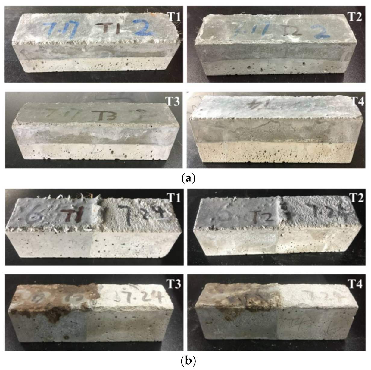
4.1.1. Appearance Changes and Explosive Spalling Property
4.1.2. Mass Change
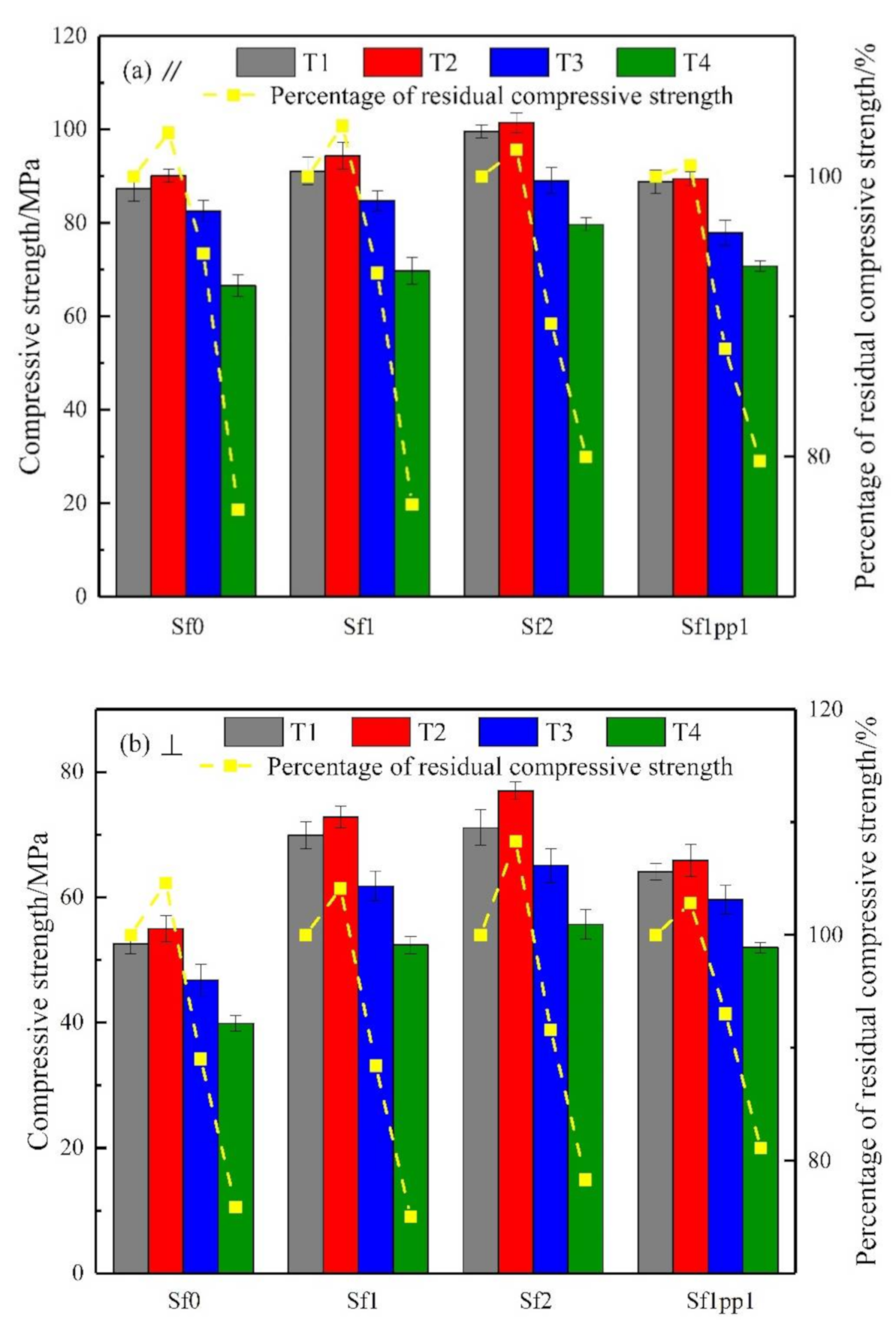
4.2. Compressive Strength
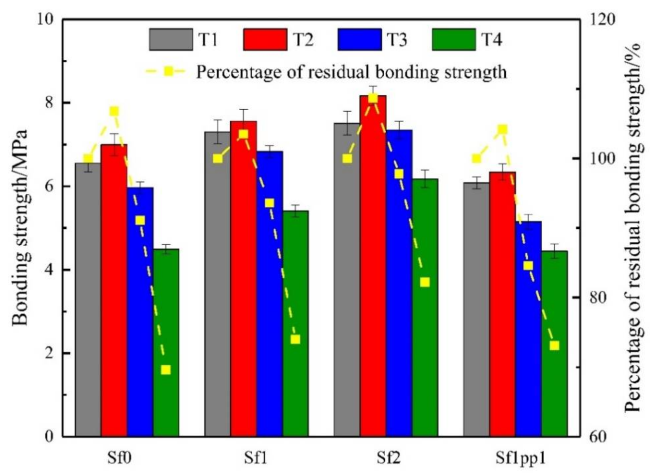
4.3. Bonding Strength
4.4. Flexural Behavior
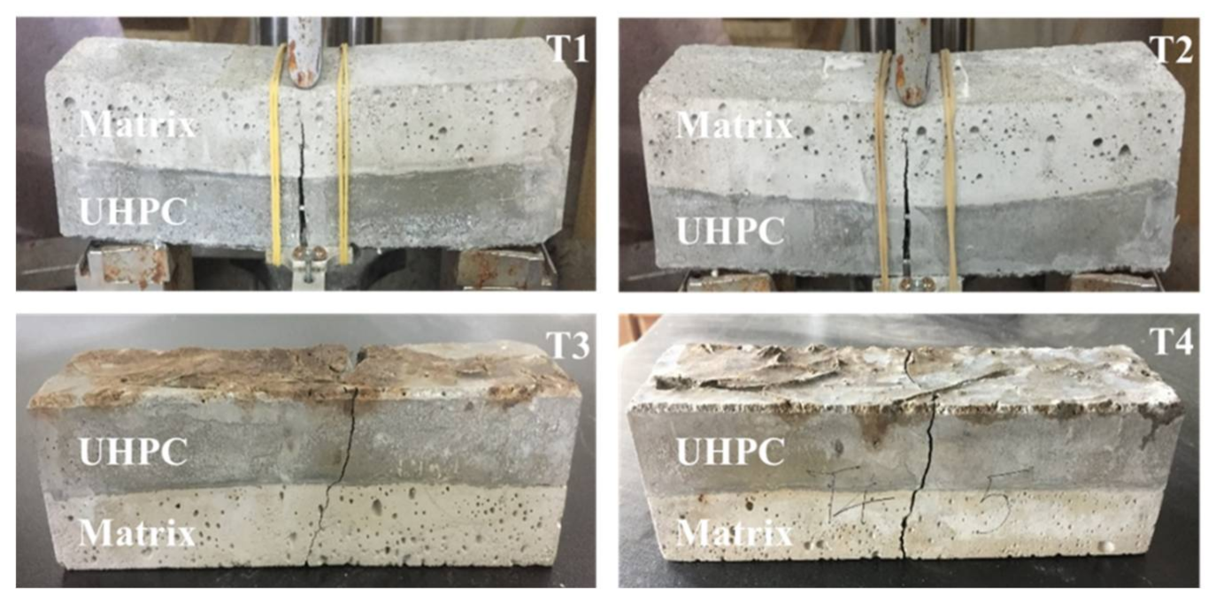
4.4.1. Failure Mode
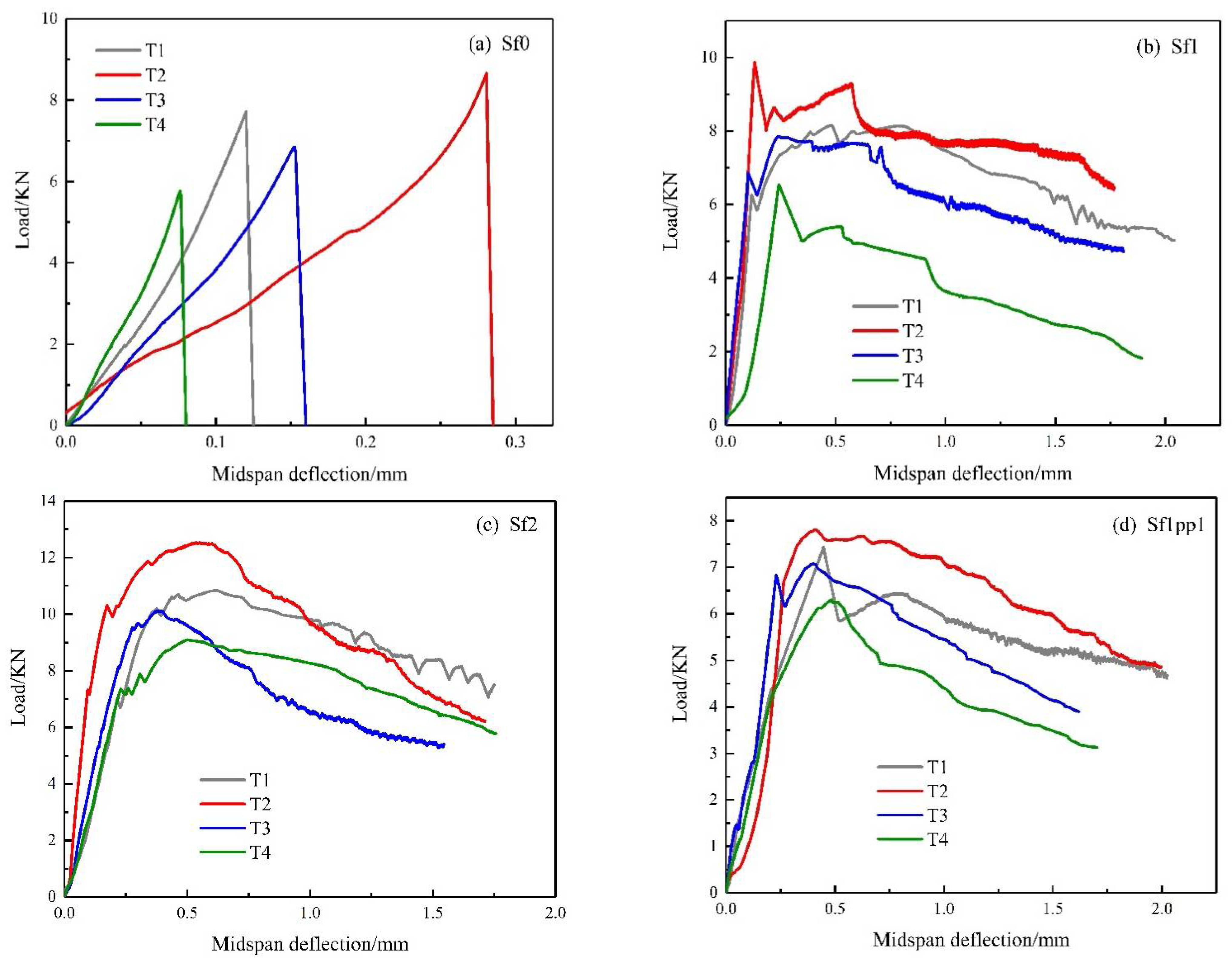
4.4.2. Load-Deflection Response
4.5. Microstructural Analysis
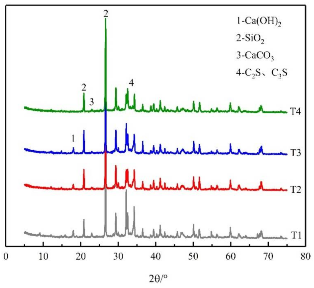
4.5.1. XRD Analysis
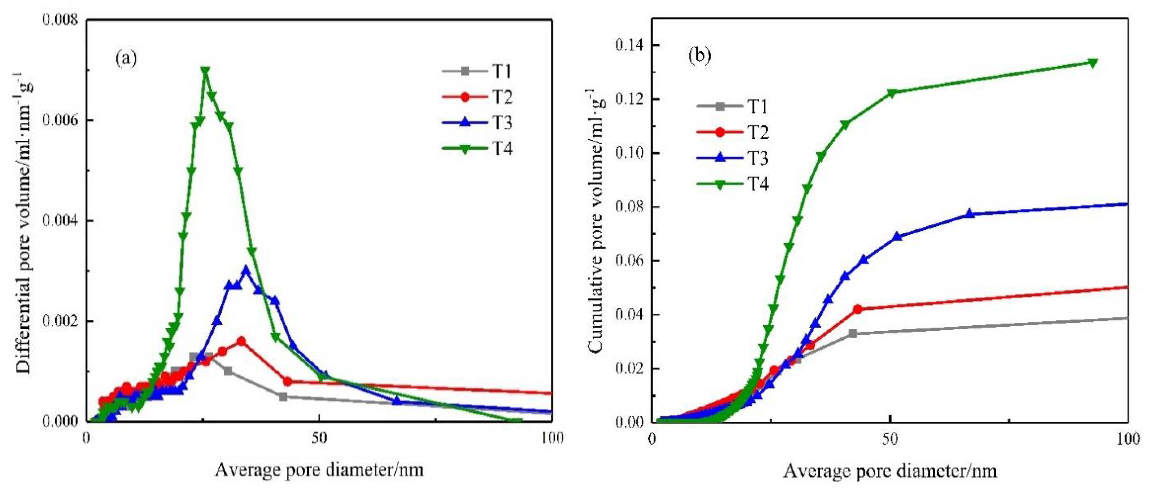
4.5.2. BET Analysis
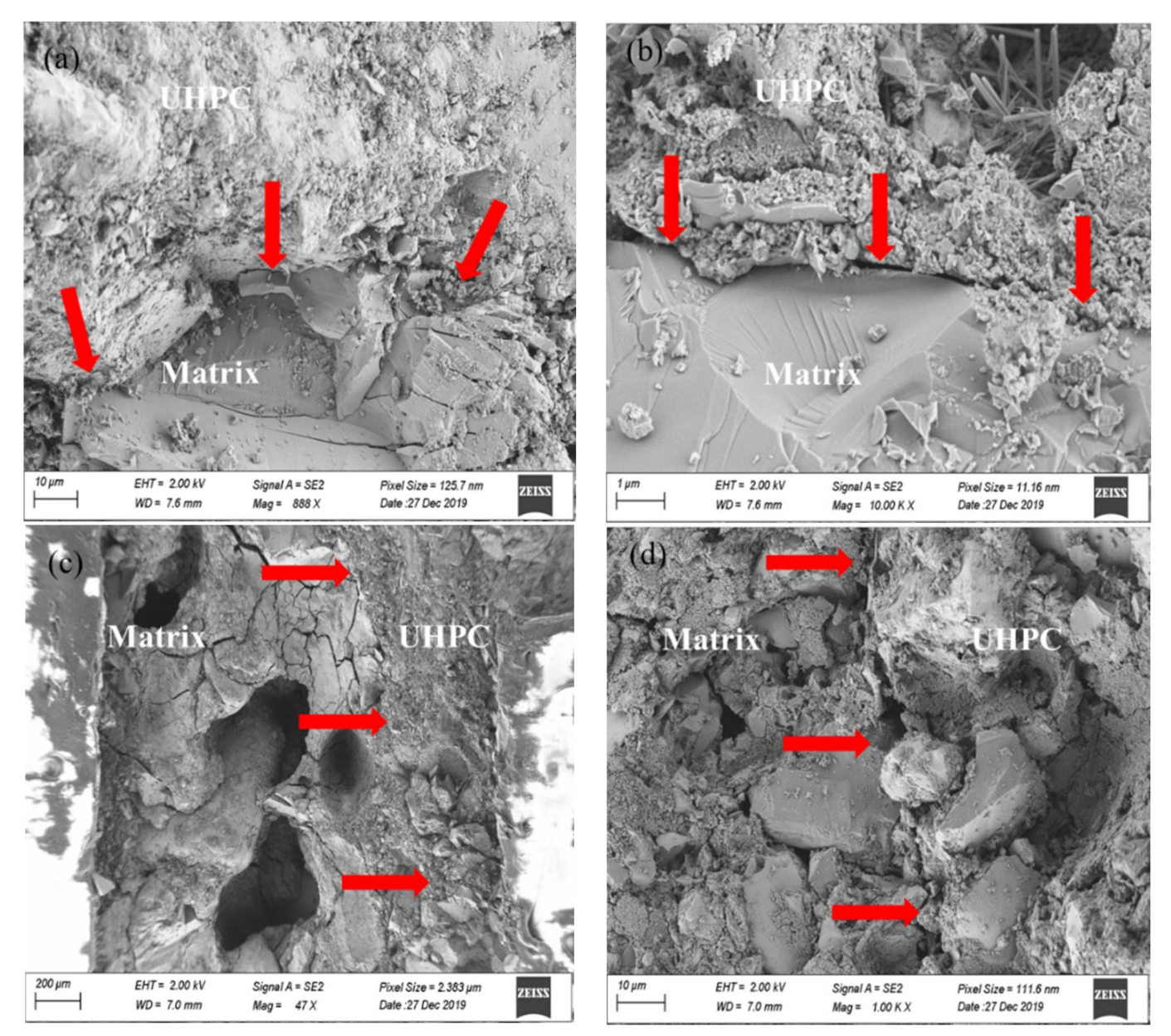
4.5.3. Scanning Electron Microscope Observations
5. Conclusions
- (1)
- After exposure to 500 °C, UHPC repaired composites change to light yellow from gray at ambient temperature and visible cracks can be observed on the surface.
- (2)
- After heating to 500 °C, the average percentage of residual mass of the system is around 94–95%, and UHPC with hybrid fibers has the best high temperature explosive spalling resistance.
- (3)
- The residual compressive strength, bonding strength, and flexural capacity exhibit a slight increase at 100 °C but then decrease with the heating temperature. For example, after heating to 500 °C, the residual compressive strength, bonding strength, and flexural capacity decrease by about 20%, 30%, and 15%, respectively. Moreover, the addition of fibers can help improve the mechanical performance of UHPC repaired composites.
- (4)
- Based on the microstructural observation, it is found that dehydration of the hydrate products, cracking, and coarsening of the pores result in the loose microstructure of the interfacial transition zone. Ultimately, the bonding performance deteriorates.
Author Contributions
Funding
Institutional Review Board Statement
Informed Consent Statement
Data Availability Statement
Conflicts of Interest
References
- Shi, C.J.; Wu, Z.M.; Xiao, J.F.; Wang, D.H.; Huang, Z.Y.; Fang, Z. A review on ultra high performance concrete: Part I. Raw materials and mixture design. Constr. Build. Mater. 2015, 101, 741–751. [Google Scholar] [CrossRef]
- Yoo, D.Y.; Kim, M.J. High energy absorbent ultra-high-performance concrete with hybrid steel and polyethylene fibers. Constr. Build. Mater. 2019, 209, 354–363. [Google Scholar] [CrossRef]
- Chen, Q.; Wang, H.; Li, H.X.; Jiang, Z.W.; Zhu, H.H.; Ju, J.W.; Yan, Z.G. Multiscale modelling for the ultra-high performance concrete: From hydration kinetics to macroscopic elastic moduli. Constr. Build. Mater. 2020, 247, 118541. [Google Scholar] [CrossRef]
- Chen, Q.; Ma, R.; Li, H.X.; Jiang, Z.W.; Zhu, H.H.; Yan, Z.G. Effect of chloride attack on the bonded concrete system repaired by UHPC. Constr. Build. Mater. 2021, 272, 121971. [Google Scholar] [CrossRef]
- Valikhani, A.; Jahromi, A.J.; Mantawy, I.M.; Azizinamini, A. Experimental evaluation of concrete-to-UHPC bond strength with correlation to surface roughness for repair application. Constr. Build. Mater. 2020, 238, 117753. [Google Scholar] [CrossRef]
- Sarkar, J. Characterization of the Bond Strength between Ultra-High Performance Concrete Substrates. Ph.D. Thesis, Michigan Technological University, Houghton, MI, USA, 2010. [Google Scholar]
- He, Y.; Zhang, X.; Hooton, R.D.; Zhang, X.W. Effects of interface roughness and interface adhesion on new-to-old concrete bonding. Constr. Build. Mater. 2017, 151, 582–590. [Google Scholar] [CrossRef]
- Hussein, L.; Amleh, L.; Siad, H.; Lachemi, M. Effect of very severe sulfate environment on bonded composite concrete system. Constr. Build. Mater. 2018, 191, 752–763. [Google Scholar] [CrossRef]
- Mahmud, G.H.; Yang, Z.; Hassan, A.M.T. Experimental and numerical studies of size effects of Ultra High Performance Steel Fiber Reinforced Concrete (UHPFRC) beams. Constr. Build. Mater. 2013, 48, 1027–1034. [Google Scholar] [CrossRef]
- Ren, G.M.; Wu, H.; Fang, Q.; Liu, J.Z. Effects of steel fiber content and type on static mechanical properties of UHPCC. Constr. Build. Mater. 2018, 163, 826–839. [Google Scholar] [CrossRef]
- Pandey, A.K. Factors affecting bond between new and old concrete. ACI Mater. J. 2012, 109, 389–390. [Google Scholar]
- Courard, L.; Piotrowski, T.; Garbacz, A. Near-to-surface properties affecting bond strength in concrete repair. Cem. Concr. Compos. 2014, 46, 73–80. [Google Scholar] [CrossRef]
- Xie, H.C.; Li, G.Y.; Xiong, G.J. Microstructure model of the interfacial zone between fresh and old concrete. J. Wuhan Univ. Technol.-Mater. Sci. Ed. 2002, 17, 64–68. [Google Scholar]
- Farzad, M.; Shafieifar, M.; Azizinamini, A. Experimental and numerical study on bond strength between conventional concrete and Ultra High-Performance Concrete (UHPC). Eng. Struct. 2019, 186, 297–305. [Google Scholar] [CrossRef]
- Li, Y.; Tan, K.H.; Yang, E.H. Influence of aggregate size and inclusion of polypropylene and steel fibers on the hot permeability of ultra-high performance concrete (UHPC) at elevated temperature. Constr. Build. Mater. 2018, 169, 629–637. [Google Scholar] [CrossRef]
- Wu, Z.; Shi, C.; Khayat, K.H. Multi-scale investigation of microstructure, fiber pullout behavior, and mechanical properties of ultra-high performance concrete with nano-CaCO3 particles. Cement Concr. Compos. 2018, 86, 255–265. [Google Scholar] [CrossRef]
- Chen, H.J.; Yu, Y.L.; Tang, C.W. Mechanical properties of Ultra-High Performance Concrete before and after exposure to high temperatures. Materials 2020, 13, 770. [Google Scholar] [CrossRef] [PubMed] [Green Version]
- Choe, G.; Kim, G.; Gucunski, N.; Lee, S. Evaluation of the mechanical properties of 200 MPa ultra-high-strength concrete at elevated temperatures and residual strength of column. Constr. Build. Mater. 2015, 86, 159–168. [Google Scholar] [CrossRef]
- Ozawa, M.; Morimoto, H. Effects of various fibres on high-temperature spalling in high-performance concrete. Constr. Build. Mater. 2014, 71, 83–92. [Google Scholar] [CrossRef]
- Zhang, D.; Tan, K.H.; Dasari, A.; Weng, Y.W. Effect of natural fibers on thermal spalling resistance of ultra-high performance concrete. Cem. Concr. Compos. 2020, 109, 103512. [Google Scholar] [CrossRef]
- Zhang, D.; Dasari, A.; Tan, K.H. On the mechanism of prevention of explosive spalling in ultra-high performance concrete with polymer fibers. Cement Concr. Res. 2018, 113, 169–177. [Google Scholar] [CrossRef]
- Zheng, W.; Luo, B.; Wang, Y. Microstructure and mechanical properties of RPC containing PP fibres at elevated temperatures. Mag. Concr. Res. 2014, 66, 397–408. [Google Scholar] [CrossRef]
- Chen, B.; Liu, J. Residual strength of hybrid-fiber-reinforced high-strength concrete after exposure to high temperatures. Cement Concr. Res. 2004, 34, 1065–1069. [Google Scholar] [CrossRef]
- Yan, Z.; Shen, Y.; Zhu, H.; Li, X.; Lu, Y. Experimental investigation of reinforced concrete and hybrid fibre reinforced concrete shield tunnel segments subjected to elevated temperature. Fire Safety J. 2015, 71, 86–99. [Google Scholar] [CrossRef] [Green Version]
- Yan, Z.; Zhang, Y.; Shen, Y.; Zhu, H.; Lu, Y. A multilayer thermo-elastic damage model for the bending deflection of the tunnel lining segment exposed to high temperatures. Tunn. Undergr. Space Technol. 2020, 95, 103142. [Google Scholar] [CrossRef]
- Yan, Z.; Shen, Y.; Zhu, H.; Lu, Y. Experimental study of tunnel segmental joints subjected to elevated temperature. Tunn. Undergr. Space Technol. 2016, 53, 46–60. [Google Scholar] [CrossRef] [Green Version]
- Zhang, Y.; Ju, J.W.; Zhu, H.; Chen, Q.; Guo, Q.; Yan, Z. A novel damage model based on micromechanics for hybrid fiber reinforced cementitious composites under uniaxial compression. Int. J. Damage Mech. 2019, 28, 1095–1132. [Google Scholar] [CrossRef]
- Zhang, Y.; Ju, J.W.; Zhu, H.; Yan, Z. A novel multi-scale model for predicting the thermal damage of hybrid fiber-reinforced concrete. Int. J. Damage Mech. 2020, 29, 19–44. [Google Scholar] [CrossRef]
- Liu, Y. Research on High Temperature Spalling Behavior of Reactive Powder Concrete. Master’s Thesis, Shijiazhuang Tiedao University, Shijiazhuang, China, 2018. [Google Scholar]
- Li, Y.; Tan, K.H.; Yang, E.H. Synergistic effects of hybrid polypropylene and steel fibers on explosive spalling prevention of ultra-high performance concrete at elevated temperature. Cem. Concr. Compos. 2019, 96, 174–181. [Google Scholar] [CrossRef]
- Sun, W.; Luo, X.; Sammy, Y.N.C. High temperature properties of high performance concrete. J. Build. Mater. 2000, 3, 27–32. [Google Scholar]
- Dong, X.J.; Ding, Y.N.; Wang, T.F. Spalling and mechanical properties of fiber reinforced high-performance concrete subjected to fire. J. Wuhan Univ. Technol.-Mater. Sci. Ed. 2008, 23, 743–749. [Google Scholar] [CrossRef]
- Li, L.J.; Xie, W.F.; Liu, F.; Chen, Y.Q.; Lu, H.X.; Wang, R.H. Performance of 100 MPa high strength concrete (HSC) after high temperature treatment. J. Build. Mater. 2008, 11, 100–104. [Google Scholar]
- Zheng, W.Z.; Li, H.Y.; Wang, Y. Compressive stress-strain relationship of hybrid fiber-reinforced reactive powder concrete after exposure to high temperature. J. Build. Mater. 2013, 16, 388–395. [Google Scholar]
- Deshpande, A.A.; Kumar, D.; Ranade, R. Influence of high temperatures on the residual mechanical properties of a hybrid fiber-reinforced strain-hardening cementitious composite. Constr. Build. Mater. 2019, 208, 283–295. [Google Scholar] [CrossRef]
- Zhang, Y.; Ju, J.W.; Chen, Q.; Yan, Z.G.; Zhu, H.H.; Jiang, Z.W. Characterizing and analyzing the residual interfacial behavior of steel fibers embedded into cement-based matrices after exposure to high temperatures. Compos. Part B-Eng. 2020, 191, 107933. [Google Scholar] [CrossRef]
- Khabaz, A. Performance evaluation of corrugated steel fiber in cementitious matrix. Constr. Build. Mater. 2016, 128, 373–383. [Google Scholar] [CrossRef]
- Rashad, A.M. Effect of steel fibers on geopolymer properties—The best synopsis for civil engineer. Constr. Build. Mater. 2020, 246, 118534. [Google Scholar] [CrossRef]
- Fernandes, B.; Moreno, A.L., Jr.; Costa, C.N. Residual bond behavior between NSM CFRP and concrete at elevated temperatures. Constr. Build. Mater. 2020, 257, 119467. [Google Scholar] [CrossRef]
- Wu, J. The Effect of High Temperature on Micro Structure and the Vapor Pressure of High Performance Concrete. Master’s Thesis, Taiyuan University of Technology, Taiyuan, China, 2016. [Google Scholar]
- Flores-Alés, V.; Martín-Del-Río, J.J.; Alducin-Ochoa, J.M.; Torres-González, M. Rehydration on high temperature-mortars based on recycled glass as aggregate. J. Clean. Prod. 2020, 275, 124139. [Google Scholar] [CrossRef]


| Oxides | CaO | MgO | Al2O3 | SiO2 | P2O5 | SO3 | K2O | Na2O | TiO2 | Cr2O3 | MnO | Fe2O3 | CuO | ZnO | SrO |
|---|---|---|---|---|---|---|---|---|---|---|---|---|---|---|---|
| Content | 65 | 0.65 | 4.56 | 20.90 | 0.12 | 2.65 | 0.87 | 0.08 | 0.22 | 0.01 | 0.09 | 3.23 | 0.01 | 0.05 | 0.03 |
| Type of Fibers | Diameter (mm) | Length (mm) | Density (g/cm3) | Tensile Strength (MPa) | Elastic Modulus (GPa) |
|---|---|---|---|---|---|
| Steel fibers | 0.2 | 13 | 7.85 | 2850 | 200 |
| PP fibers | 0.1 | 40 | 0.91 | 600 | 10 |
| Material | Cement | Silica Fume | Quartz Powder | Quartz Sand | Sand | Superplasticizer | Water |
|---|---|---|---|---|---|---|---|
| UHPC | 743 | 90 | 250 | 1070 | 7.15 | 193 | |
| Matrix | 500 | 1500 | 0.6 | 220 |
| Group | Category | Steel Fiber (%) | PP Fiber (%) | 28d Compressive Strength (MPa) |
|---|---|---|---|---|
| 1 | Sf0 | 131.2 | ||
| 2 | Sf1 | 1 | 155.9 | |
| 3 | Sf2 | 2 | 164.4 | |
| 4 | Sf1pp1 | 1 | 1 | 150.6 |
Publisher’s Note: MDPI stays neutral with regard to jurisdictional claims in published maps and institutional affiliations. |
© 2021 by the authors. Licensee MDPI, Basel, Switzerland. This article is an open access article distributed under the terms and conditions of the Creative Commons Attribution (CC BY) license (https://creativecommons.org/licenses/by/4.0/).
Share and Cite
Chen, Q.; Zhu, Z.; Ma, R.; Jiang, Z.; Zhang, Y.; Zhu, H. Insight into the Mechanical Performance of the UHPC Repaired Cementitious Composite System after Exposure to High Temperatures. Materials 2021, 14, 4095. https://doi.org/10.3390/ma14154095
Chen Q, Zhu Z, Ma R, Jiang Z, Zhang Y, Zhu H. Insight into the Mechanical Performance of the UHPC Repaired Cementitious Composite System after Exposure to High Temperatures. Materials. 2021; 14(15):4095. https://doi.org/10.3390/ma14154095
Chicago/Turabian StyleChen, Qing, Zhiyuan Zhu, Rui Ma, Zhengwu Jiang, Yao Zhang, and Hehua Zhu. 2021. "Insight into the Mechanical Performance of the UHPC Repaired Cementitious Composite System after Exposure to High Temperatures" Materials 14, no. 15: 4095. https://doi.org/10.3390/ma14154095
APA StyleChen, Q., Zhu, Z., Ma, R., Jiang, Z., Zhang, Y., & Zhu, H. (2021). Insight into the Mechanical Performance of the UHPC Repaired Cementitious Composite System after Exposure to High Temperatures. Materials, 14(15), 4095. https://doi.org/10.3390/ma14154095