
Deflection Estimation Based on the Thermal Characteristics of Composite Deck Slabs Containing Macro-Synthetic Fibers


Abstract
:1. Introduction
2. Specimens and Test Methods
2.1. Materials
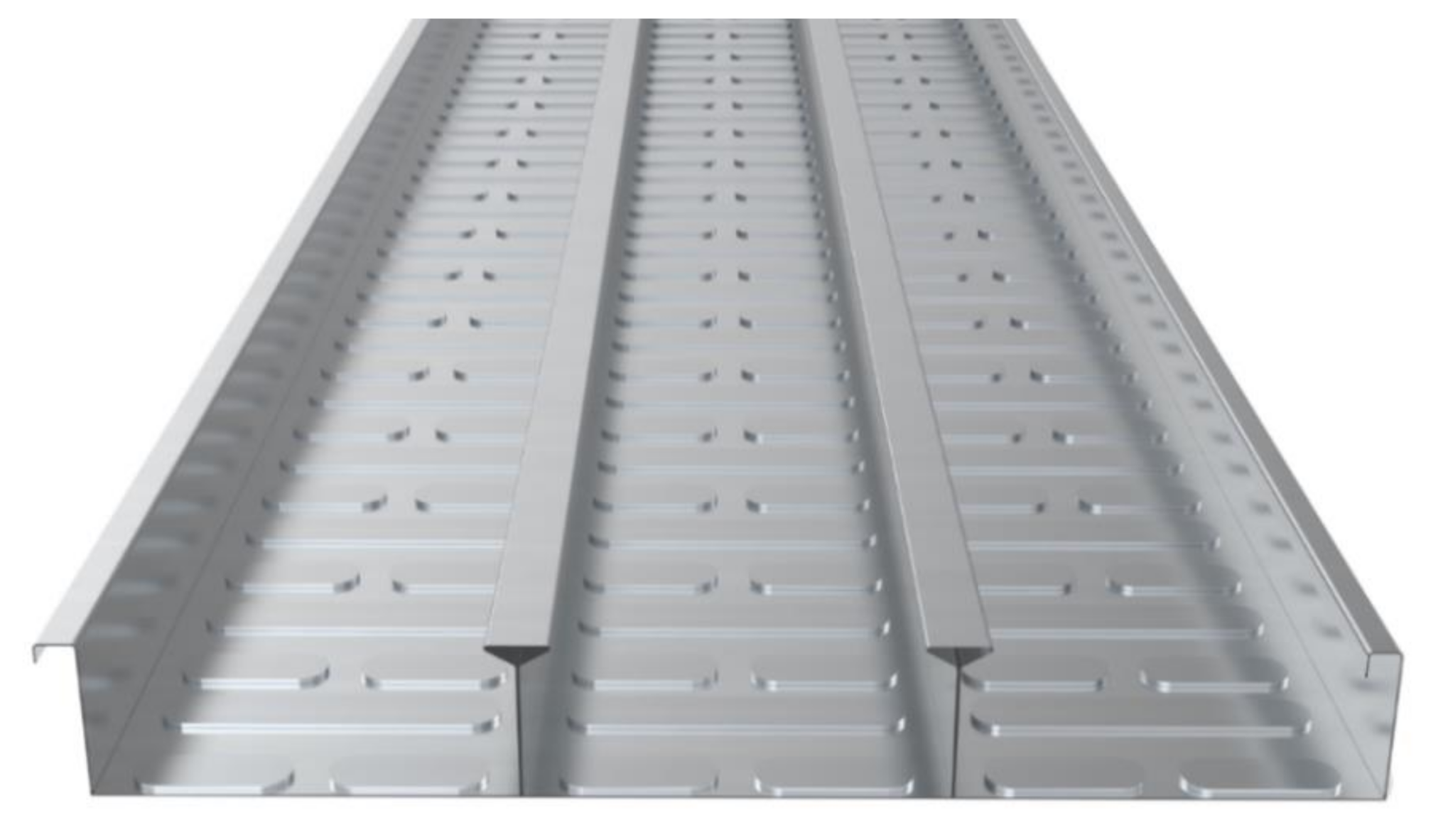
2.1.1. Deck Plate
2.1.2. Characteristics of the Macro-Fiber
2.2. Material Test
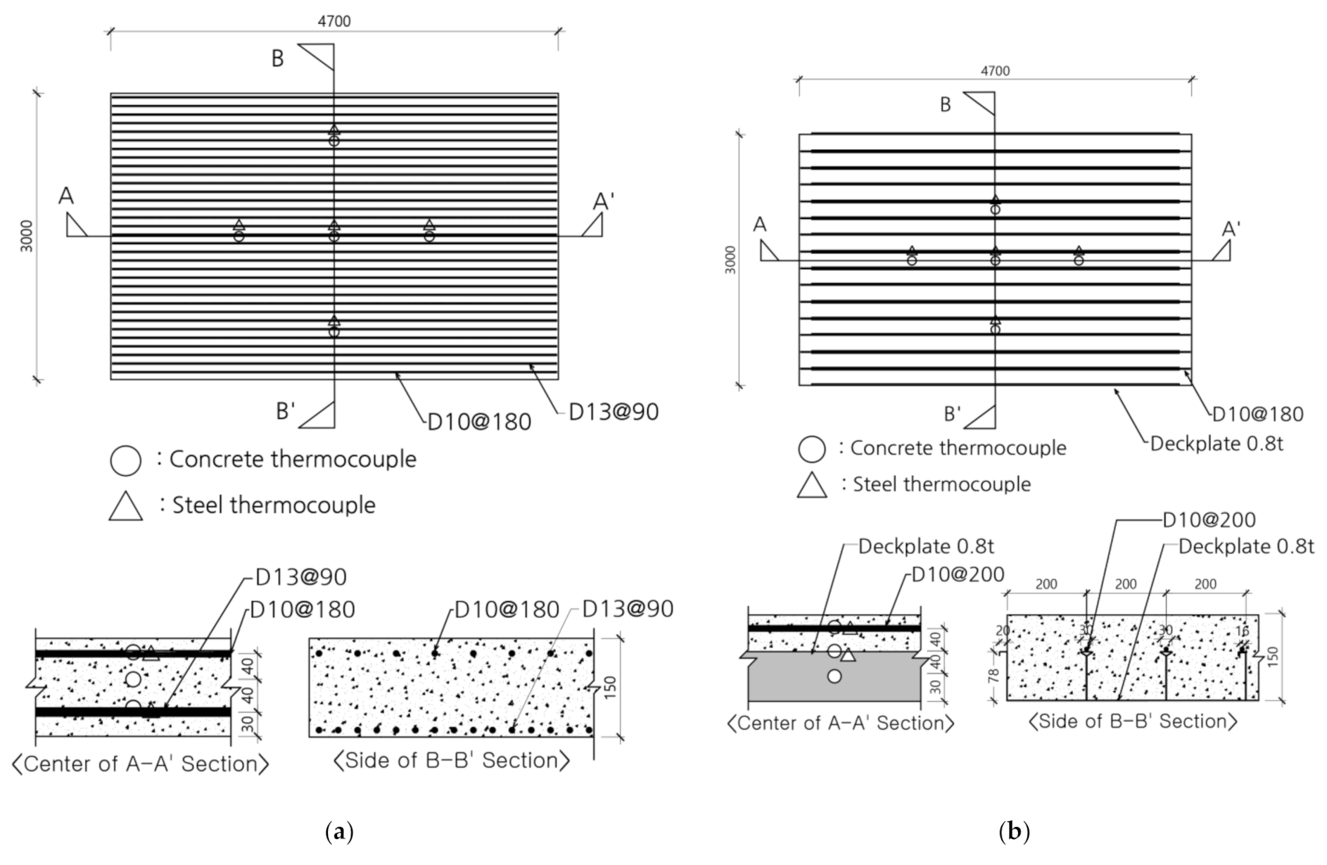
2.3. Test Plan and Specimen Design
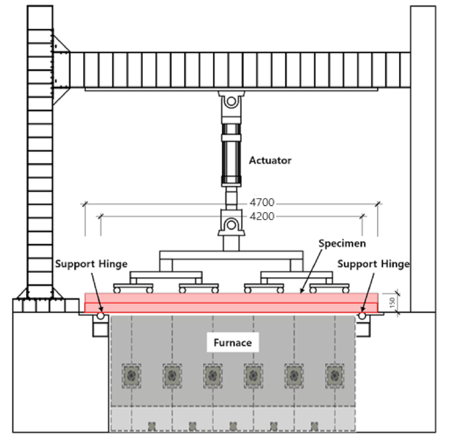
2.4. Test Method and Setup
- t: Fire occurrence time (min)
- : Average temperature in the heating furnace (°C)
- : Air temperature (20 °C)
- : Span (mm)
- d: The distance from the position designed to receive the maximum compressive force of the structural section to the position designed to receive the maximum tensile force (mm)
3. Test Results
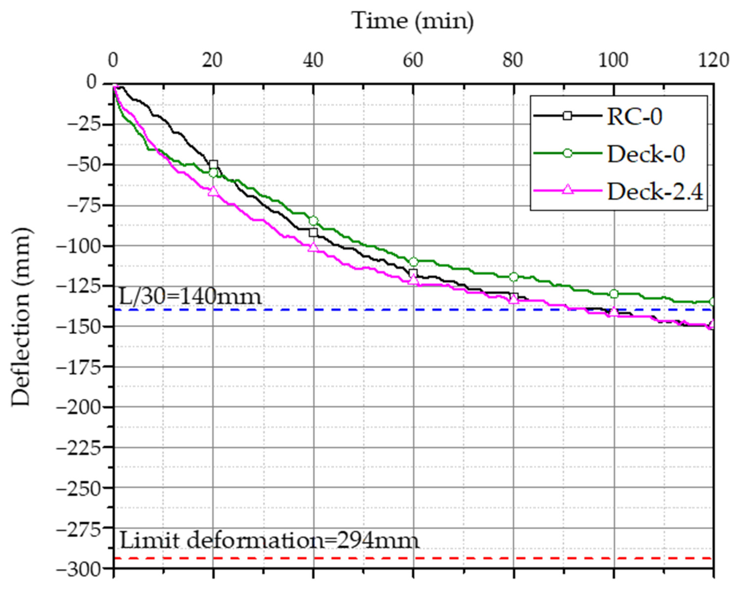
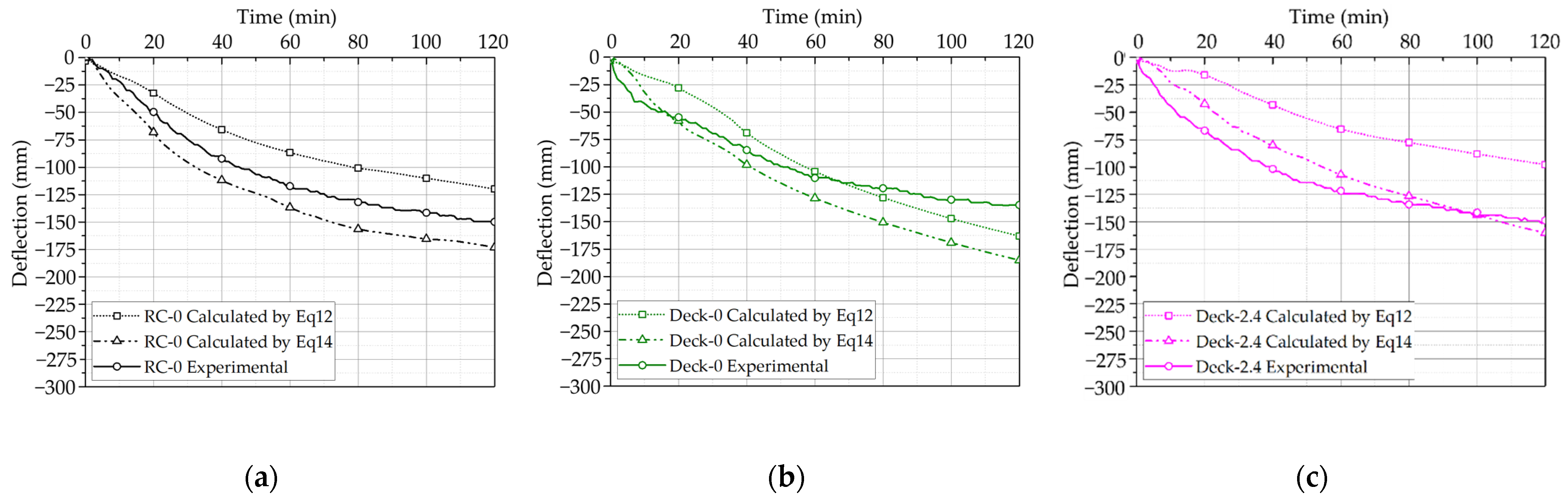
3.1. Deflection Change According to Temperature
3.2. Thermal Properties of the Deck Slabs
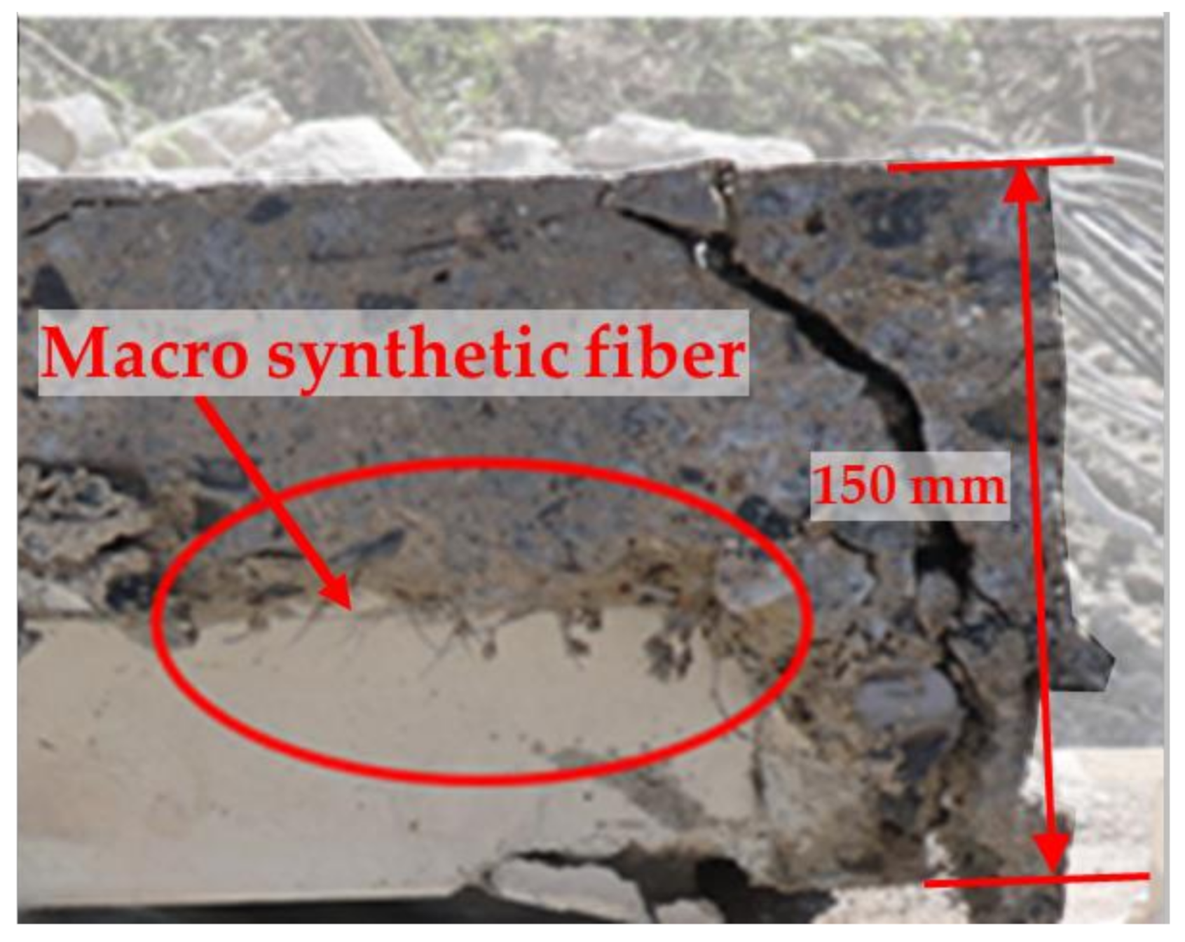
3.3. Thermal Properties of Deck Slabs with Macro-Synthetic Fibers
4. Deflection Estimation of Composite Deck Plate Slab Exposed to High Temperatures
- -
- The sum of compressive stresses occurring in the member is always equal to the sum of the tensile stresses.
- -
- The moment generated by compression and tension force is the same as the applied moment.
5. Conclusions
- (1)
- Based on the results of a fire test on the deck slab, RC-0, Deck-0, and Deck-2.4 all satisfied the fire resistance certification time of 120 min for the floor member.
- (2)
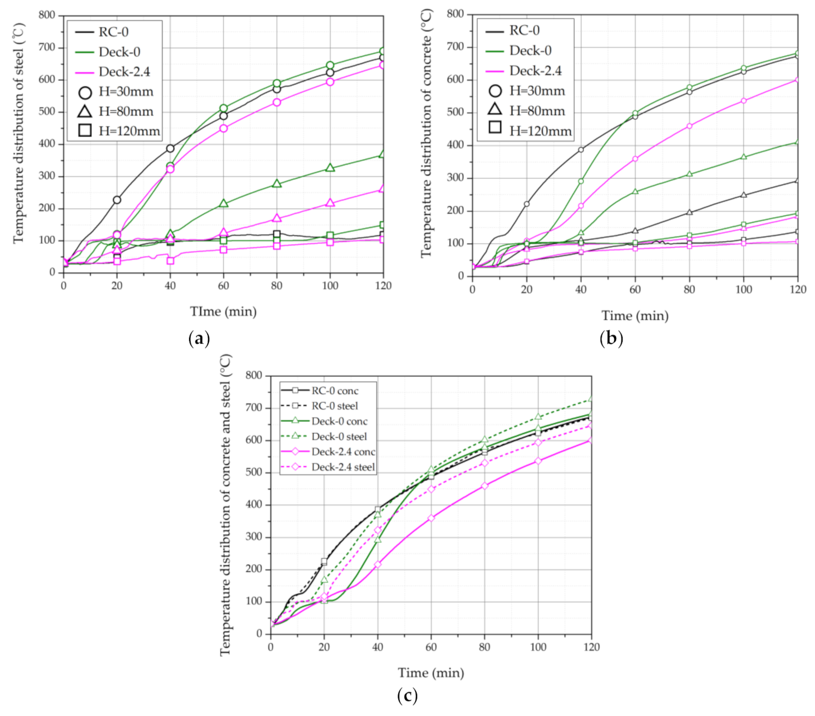
- Based on an analysis of the temperature distribution of the deck slab, the temperature increase was delayed in a section after a certain time, which is believed to have affected the overall temperature increase.
- (3)
- The internal temperature of Deck-0 was the highest compared with other specimens, but the deformation was the lowest. This is believed to have reduced the deformation of the deck plate because the composite effect increased due to the ribs arranged in the web and the Y-shape flange at the end of the ribs.
- (4)
- Based on an analysis of the thermal properties of the macro-synthetic fibers, Deck-2.4 (containing macro-synthetic fibers) had the lowest backside temperature compared with the other test specimens with a deformation difference of 16.7 mm compared with Deck-0. Therefore, the incorporation of macro-synthetic fibers is effective in preventing an increase in the temperature inside the slab, although it did not cause any reduction in the amount of deformation.
- (5)
- When estimating deflection due to thermal load for the deck slab, the temperature distribution should be applied differently for each method of estimating deflection. In addition, the method for estimating deflection due to axial force was found to safely evaluate the fire resistance performance of a deck slab.
- (6)
- If the estimation of the temperature distribution considering the thermal characteristics of the deck slab and macro-synthetic fiber is derived in the future, the deflection of the slab in case of fire can be derived analytically without relying on experiments by applying the deflection evaluation method performed in this study. In addition, it is necessary to analyze the effect of the length and angle of the rib and the Y-shape on the fire resistance performance of the deck plate later through finite element analysis.
Author Contributions
Funding
Institutional Review Board Statement
Informed Consent Statement
Data Availability Statement
Conflicts of Interest
References
- Ji, N.Y.; Hui, C.; Kim, J.H.; Eum, C.W.; Lee, K.K.; Suh, C.H.; Moon, T.S.; Kim, G.S.; Kim, D.J.; Kim, D.K. The Evaluation of Fire Resistant Performance of the Metal Deck Slab System. J. Korea Archit. Inst. 1996, 16, 571–574. [Google Scholar]
- Son, D.H.; Bae, B.I.; Lee, M.S.; Lee, M.S.; Choi, C.S. Flexural Strength of Composite Deck Slab with Macro Synthetic Fiber Reinforced Concrete. Appl. Sci. 2021, 11, 1662. [Google Scholar] [CrossRef]
- Lee, M.S.; Chung, J.H.; Son, D.H.; Choi, C.S. Flexural Strength Evaluation of Reinforced Concrete Slabs with Macro Synthetic Fibers. J. Archit. Inst. Korea 2020, 36, 241–248. [Google Scholar]
- Chung, J.H.; Cho, H.J.; Lee, S.C.; Choi, H.K.; Choi, C.S. An Experimental Study on the Fire Resistance Performance for the Donut Type Biaxial Hollow Slab. J. Korea Archit. Inst. 2012, 28, 3–10. [Google Scholar]
- Won, J.P.; Jang, C.; Lee, S.; Kim, H.; Kim, W. Fire Resistance Performance for Hybrid Fiber Reinforced High Strength Concrete Column Member. J. Korea Concr. Inst. 2008, 20, 827–832. [Google Scholar]
- Zainal, S.M.; Hejazi, F.; Abd Aziz, F.N.; Jaafar, M.S. Effects of Hybridized Synthetic Fibers on the Shear Properties of Cement Composites. Materials 2020, 13, 5055. [Google Scholar] [CrossRef]
- Shafei, B.; Kazemian, M.; Dopko, M.; Najimi, M. State-of-the-Art Review of Capabilities and Limitations of Polymer and Glass Fibers Used for Fiber-Reinforced Concrete. Materials 2021, 14, 409. [Google Scholar] [CrossRef]
- Alberti, M.G.; Gálvez, J.C.; Enfedaque, A.; Castellanos, R. Influence of High Temperature on the Fracture Properties of Polyolefin Fibre Reinforced Concrete. Materials 2021, 14, 601. [Google Scholar] [CrossRef]
- Maraveas, C.; Vrakas, A.A. Design of Concrete Tunnel Linings for Fire Safety. Struct. Eng. Int. 2014, 24, 319–329. [Google Scholar] [CrossRef] [Green Version]
- Phan, L.T. Pore Pressure and Explosive Spalling in Concrete. Mater. Struct. 2008, 41, 1623–1632. [Google Scholar] [CrossRef]
- Bangi, M.R.; Horiguchi, T. Pore Pressure Development in Hybrid Fibre-Reinforced High Strength Concrete at Elevated Temperatures. Cem. Concr. Res. 2011, 41, 1150–1156. [Google Scholar] [CrossRef] [Green Version]
- Horrocks, A.R.; Kandola, B.K.; Smart, G.; Zhang, S.; Hull, T.R. Polypropylene Fibers Containing Dispersed Clays Having Improved Fire Performance. J. Appl. Polym. Sci. 2007, 106, 1707–1717. [Google Scholar] [CrossRef]
- Kang, S.W.; Hong, S.G. Material Model and thermal Response Analysis of Concrete at Elevated Temperatures. Korea Concr. Inst. 2001, 13, 268–276. [Google Scholar]
- Kang, S.W.; Hong, S.G. Analysis of the Reinforced Concrete Flexural Members Subjected to High Temperatures. J. Korea Archit. Inst. 2004, 20, 51–58. [Google Scholar]
- CEN (European Committee for Standardization). EN 1992-1-2 Eurocode 2: Design of Concrete Structures—Part 1–2: General Rules—Structural Fire Design; European Committee for Standardization: Brussels, Belgium, 2004. [Google Scholar]
- CEN (European Committee for Standardization). EN 1993-1-2 Eurocode 3: Design of Steel Structures—Part 1–2: General Rules—Structural Fire Design; European Committee for Standardization: Brussels, Belgium, 2005. [Google Scholar]
- ISO 834. Fire Resistance Tests-Elements of Building Construction; ISO 834-1:1999; International Organization for Standardization (ISO): Geneva, Switzerland, 1999. [Google Scholar]
- Korean Agency for Technology and Standards. KS F 1611-4 Standard for Fire Resistance Performance of Building Structure Members—Part 4: Composite Deck Floor Structure; Korean Agency for Technology and Standards: Seoul, Korea, 2015; pp. 1–16.
- Korean Agency for Technology and Standards. KS F 2257-5 Methods of Fire Resistance Test for Elements of Building Construction—Specific Requirements for Loadbearing Horizontal Separating Elements; Korean Agency for Technology and Standards: Seoul, Korea, 2014; pp. 1–16.
- ACI Committee. ACI 216.1-14, Code Requirements for Determining Fire Resistance of Concrete and Masonry Construction Assemblies; ACI Committee: Farmington Hill, MI, USA, 2014. [Google Scholar]
- ACI Committee. ACI 318-19. Building Code Requirement for Structural Concrete and Commentary; ACI Committee: Farmington Hill, MI, USA, 2019. [Google Scholar]
- FORTA-FERRO Company. Macro Synthetic Fiber Technical Report; FORTA Concrete Fiber Company: Grove City, PA, USA, 2018. [Google Scholar]
- Ryu, H.S.; Kim, D.M.; Shin, S.H.; Ryu, I.H.; Joe, J.M. Evaluation on Mechanical Properties of Organic of Fiber Reinforced Concrete Using Macro Forta Fiber. Korea Inst. Build. Constr. 2017, 17, 321–329. [Google Scholar] [CrossRef]
- Salvador, R.P.; Estrada, A.R.; Figueiredo, A.D. Characterization of Self-Fibrillating Synthetic Macrofibers for Concrete Reinforcement. In Proceedings of the 7th International Conference Fibre Concrete, Prague, Czech Republic, 17–20 September 2019; pp. 1–10. [Google Scholar]
- Korean Agency for Technology and Standards. KS F 2405. Standard Test Method for Compressive Strength of Concrete; Korean Agency for Technology and Standards: Seoul, Korea, 2014; pp. 1–16.
- Korean Agency for Technology and Standards. KS F 2408. Method of Test for Flexural Strength of Concrete; Korean Agency for Technology and Standards: Seoul, Korea, 2016; pp. 1–16.
- Taerwe, L.; Matthys, S. Fib Model Code for Concrete Structures 2010; Ernst & Sohn, Wiley: Berlin, Germany, 2013. [Google Scholar]
- Korean Agency for Technology and Standards. KS D 3506. Hot-Dip Zinc-Coated Steel Sheets and Coil; Korean Agency for Technology and Standards: Seoul, Korea, 2018; pp. 1–60.
- Cho, H.J. Evaluation Method of Flexural Strength and Deflection for Donut Type Two-Way Hollow Slab at Elevated Temperature. Master’s Thesis, Hanyang University, Seoul, Korea, 2012. [Google Scholar]
- Choi, H.K.; Choi, C.S. Analysis Study on Thermal Properties of Hollow Slab at Elevated Temperature. J. Korean Soc. Hazard Mitig. 2015, 15, 17–23. [Google Scholar]
- Choi, H.K.; Chung, J.H.; Choi, C.S. Estimation Method of Residual Performance for Hollow Slab at Elevated Temperature. J. Korea Concr. Inst. 2014, 26, 643–650. [Google Scholar] [CrossRef] [Green Version]
- Wang, Y.; Yuan, G.; Huang, Z.; Lyu, J.; Li, Q.; Long, B. Modelling of Reinforced Concrete Slabs in fire. Fire Saf. J. 2018, 100, 171–185. [Google Scholar] [CrossRef]
- Han, C.G.; Yang, S.H.; Lee, B.Y.; Hwang, Y.S.; Jun, S.C. Properties of Fire Resistance of High Performance Concrete with Varying Contents of Polypropylene Fiber and Specimen Size. J. Korea Concr. Inst. 2002, 14, 449–456. [Google Scholar]
- Jang, C.I.; Kim, J.M.; Kang, H.B.; Yoon, Y.N.; Kim, W.Y.; Won, J.P. Evaluation of Thermal Effect for PP fiber Reinforced Lightweight Aggregate Polymer Mortar. Proc. Korea Concr. Inst. 2009, 21, 215–216. [Google Scholar]
- Khoury, G.A. Effect of Fire on Concrete and Concrete Structures. Prog. Struct. Eng. Mater. 2000, 2, 429–447. [Google Scholar] [CrossRef]
- Mohammadhosseini, H.; Alrshoudi, F.; Tahir, M.M.; Alyousef, R.; Alghamdi, H.; Alharbi, Y.R.; Alsaif, A. Durability and Thermal Properties of Prepacked Aggregate Concrete Reinforced with Waste Polypropylene Fibers. J. Build. Eng. 2020, 32, 101723. [Google Scholar] [CrossRef]


| Thickness (mm) | Weight (kg/m2) | Section Area (mm2) | Centroid (mm) |
|---|---|---|---|
| 0.8 | 14.47 | 1075.2 | 25.29 |
| Material | Tensile Strength (MPa) | Modulus of Elasticity (GPa) | Length (mm) | Diameter (µm) | Aspect Ratio |
|---|---|---|---|---|---|
| Polypropylene | 54.9 | 4.7 | 54 | 0.34 | 159 |
| W/C (%) | S/a (%) | Unit Weight (kg/m3) | |||||
|---|---|---|---|---|---|---|---|
| C | W | S | G | AD | MF | ||
| 54.9 | 45.5 | 365 | 200.7 | 854 | 1022.7 | 3.29 | 0 |
| 2.4 | |||||||
| Day | No. | (kg/m3) | |||
|---|---|---|---|---|---|
| 28 | 1 | 0 | 34.70 | 0.00163 | 38,912 |
| 2 | 34.98 | 0.00167 | 35,457 | ||
| 3 | 35.74 | 0.00143 | 41,128 | ||
| 90 | 1 | 37.6 | 0.00158 | 32,696 | |
| 2 | 38.49 | 0.00169 | 37,551 | ||
| 3 | 39.41 | 0.0018 | 32,245 | ||
| 28 | 1 | 2.4 | 39.35 | 0.00164 | 42,408 |
| 2 | 40.94 | 0.00140 | 46,054 | ||
| 3 | 39.89 | 0.00194 | 32,934 | ||
| 90 | 1 | 36.19 | 0.00173 | 35,558 | |
| 2 | 33.89 | 0.00128 | 38,126 | ||
| 3 | 26.77 | 0.00164 | 33,463 |
| Day | No. | (kg/m3) | ||||
|---|---|---|---|---|---|---|
| 28 | 1 | 0 | 3.708 | - | - | - |
| 2 | 3.308 | - | - | - | ||
| 3 | - | - | - | - | ||
| 1 | 2.4 | 3.456 | 1.252 | 1.204 | 1.104 | |
| 2 | 3.708 | 0.904 | 0.904 | 0.706 | ||
| 3 | 3.906 | 0.754 | 0.704 | 0.704 |
| Specimen | Thickness (mm) | Length (m) | Width (m) | Macro-Synthetic Fibers (kg/m3) | Concrete Cover Thickness (mm) | Top Rebar | Bottom Rebar | Uniform Load (kN/m2) | |
|---|---|---|---|---|---|---|---|---|---|
| Top | Bottom | ||||||||
| RC-0 | 150 | 4.7 | 3.0 | 0 | 20 | 20 | D10@200 | D13@90 | 7.2 |
| Deck-0 | 0 | - | - | ||||||
| Deck-2.4 | 2.4 | - | - | ||||||
| Specimen | Displacement (mm) | Rate of Displacement (mm/min) | Temperature Increase at Unheated Surface (°C) | Fire Resistance Performance (O/X) | |||
|---|---|---|---|---|---|---|---|
| Limitation | Measured | Limitation | Measured | Average | Maximum | ||
| RC-0 | 294 | 149.8 | 13 | 5.7 | 79.4 | 102.1 | O |
| Deck-0 | 294 | 134.8 | 13 | 8.0 | 99.3 | 158.4 | O |
| Deck-2.4 | 294 | 151.5 | 13 | 6.6 | 65.0 | 69.8 | O |
| Specimen | Measurement | Temperature (°C) at 120 min | |||||
|---|---|---|---|---|---|---|---|
| Rebar and Deck Plate | Concrete | ||||||
| 30 mm | 80 mm | 120 mm | 30 mm | 80 mm | 120 mm | ||
| RC-0 | Average | 582.6 | - | 115.3 | 487.8 | 225.3 | 114.6 |
| Maximum | 670.4 | - | 149.0 | 673.2 | 292.5 | 137.6 | |
| Deck-0 | Average | 642.0 | 292.6 | 116.8 | 480.5 | 255.4 | 134.3 |
| Maximum | 728.3 | 367.3 | 149.3 | 682.8 | 410.2 | 193.4 | |
| Deck-2.4 | Average | 609.8 | 292.0 | 101.1 | 458.8 | 189.5 | 102.6 |
| Maximum | 646.8 | 379.2 | 103.6 | 601.7 | 237.7 | 107.4 | |
Publisher’s Note: MDPI stays neutral with regard to jurisdictional claims in published maps and institutional affiliations. |
© 2021 by the authors. Licensee MDPI, Basel, Switzerland. This article is an open access article distributed under the terms and conditions of the Creative Commons Attribution (CC BY) license (https://creativecommons.org/licenses/by/4.0/).
Share and Cite
Son, D.-H.; Ahn, H.-J.; Chung, J.-H.; Bae, B.-I.; Choi, C.-S. Deflection Estimation Based on the Thermal Characteristics of Composite Deck Slabs Containing Macro-Synthetic Fibers. Materials 2021, 14, 4052. https://doi.org/10.3390/ma14144052
Son D-H, Ahn H-J, Chung J-H, Bae B-I, Choi C-S. Deflection Estimation Based on the Thermal Characteristics of Composite Deck Slabs Containing Macro-Synthetic Fibers. Materials. 2021; 14(14):4052. https://doi.org/10.3390/ma14144052
Chicago/Turabian StyleSon, Dong-Hee, Hyo-Jun Ahn, Joo-Hong Chung, Baek-Il Bae, and Chang-Sik Choi. 2021. "Deflection Estimation Based on the Thermal Characteristics of Composite Deck Slabs Containing Macro-Synthetic Fibers" Materials 14, no. 14: 4052. https://doi.org/10.3390/ma14144052
APA StyleSon, D.-H., Ahn, H.-J., Chung, J.-H., Bae, B.-I., & Choi, C.-S. (2021). Deflection Estimation Based on the Thermal Characteristics of Composite Deck Slabs Containing Macro-Synthetic Fibers. Materials, 14(14), 4052. https://doi.org/10.3390/ma14144052