1. Introduction
Because of its excellent self-lubricating properties, the porous oil-containing cage is widely used in support bearings of major equipment in field of aerospace and precision slewing. During bearing service period, lubricants which are stored in the micron-submicron pores of the porous cage flow out under the effect of the centrifugal force and thermal effect. When bearing speed slows down or the temperature drops, the capillary force of micro-scale pore structure plays a key role to suck back the lubricating oil, thus, the self-lubrication of the porous oil-containing cage is realized [
1]. As the speed of the cage rises, the lubricant overflows from the micro-pores of the cage under the combined effect of centrifugal force and thermal effect. Then, when the speed of the cage decreases or the cage stops working, the lubricant is sucked back into the cage and stored under the capillary action of the micropores, thus realizing the circulating lubrication of the lubricant in the porous oil-containing cage. It can be seen that the shape of the micro-scale pore structure, the material properties of the lubricating medium and the coupling effect of the flow and heat transfer directly affect the oil flow resistance characteristics inside the porous structure, which is key to maintaining a good self-lubricating performance for the porous cage.
At present, the research literature on the lubrication performance of porous oil-containing cages mainly focuses on experimental studies. For example, Yan [
2] and Shi [
3] investigated the friction and wear characteristics of porous cage with different pore-forming agent content. Results show that the content of pore-forming agents is proportional to the size of the micro-scale pore structure, which can be used to control the lubrication performance of the porous oil-containing cage. Through scanning electron microscope images, Qiu [
4] found that the porous PI material presents a through-hole structure with an “ink bottle” shape, and it has a uniform pore size distribution. The experimental work shows that the value of porosity directly determines the oil content performance of the oil-containing material. From the above experimental studies, it can be concluded that porous structure has a great influence on the lubrication performance of the porous oil-containing material. However, experimental research mainly focuses on the effects of different oil content and porosity on its tribology performance and self-lubrication from a macro perspective. However, analysis of the oil flow process and mechanism inside the micro-scale pores, especially with the effect of multi-force field, is still lacking. This is due to the structural characteristics of porous materials, such as randomness, complexity and micron/submicron scales, thus leading to great difficulties in structural modeling. To this end, a porous model was reconstructed by X-ray CT scanning technology for the porous material [
5,
6]. Based on the reconstruction data of the porous model, the geometry and interconnection data of the porous model were extracted. For example, Celik et al. found the volume-averaged (i.e., macroscopic) transport properties, such as permeability and inertia coefficient, of two aluminum foams with 10 and 20 pores per inch (PPI) pore density using microtomography images and further adopting a variety of inspection methods to verify the results obtained. [
7] Furthermore, a simplified geometric model of porous materials was established by the authors of [
8,
9] by using the maximum sphere method to turn the microchannel into pores and throats. Since the porous oil-containing cage is generally formed by cold-press sintering, its internal pore size is between 0.5 μm and 5 μm [
10]. However, the highest accuracy of the current X-ray technology is 0.699 μm, which makes it difficult to precisely scan and identify the micro-scale pore structures, causing the reconstruction model seriously distorted.
In the analysis of the internal flow mechanism of porous materials, the commercial software is usually employed to simulate the flow process in porous media. For instance, Wang [
11] theoretically analyzed the seepage equation and heat conduction conditions in porous medium, and the simulation analysis were carried out by ANSYS, the seepage process and stress field in porous medium under special circumstances were obtained. Based on COMSOL Multiphysics platform, Yue [
12] analyzed the seepage law in porous media, and the result showed that the seepage of lubricating oil in the material was mainly related to the pore structure and external energy. Nevertheless, due to the particularity of the porous cage structure, the current micro-scale pore models of flow analysis on the porous material are not accurate, and the detailed characterization of the porous structure is lacking.
In order to investigate the seepage mechanism in porous media and solve the continuity equation, momentum equation and energy equation of fluid flow, the porous media were often regarded as continuous media and their micro-structure characteristics were ignored. The common theoretical models for the seepage law of porous media include Darcy’s law, the Nonlinear Permeability law and the Ergun equation (K1 = 150, K2 = 1.75) [
13,
14,
15], which were all derived from a number of particle bed experimental studies. Therefore, these models were all empirical and semi-empirical equations to describe the permeation laws of porous media. According to those equations, researchers proposed different empirical coefficients. For example, in MacDonald’s [
16] study, K1 = 180 and K2 = 1.8. Wyllie [
17] recommended K1 = 172.8 by calculating the characteristic length and shape factor of the particles. Furthermore, Fand [
18] studied the parameters K1 and K2 of the Ergun equation and found that when the Reynolds number range was 5 to 80, K1 = 182 and K2 = 1.92, while the Reynolds number was greater than 120, K1 = 225 and K2 = 1.61. From these studies, it can be concluded that with different research object and experiment conditions, the empirical equations for flow resistance loss in porous media have different empirical coefficients, indicating that the current empirical and semi-empirical equations have large errors and fail to accurately represent the permeability law in general porous media.
Based on the above discussion, the traditional flow resistance model and related theories cannot be directly applied to the study of the seepage mechanism in porous medium. In this paper, a new modeling method of porous cage was proposed based on random seeds theory, and the local two-dimensional models of porous cages with different micro-scale pore structure were established. In order to characterize the micro-scale pore structure, new structural parameters, such as relative surface perimeter, effective porosity, tortuosity and fluid properties related to the internal flow process, were all extracted from the new models. The verification between the flow resistance model inside porous medium and the simulation results shows the effectiveness of the method proposed in this paper.
2. Micro-Scale Pores Modeling
2.1. Modeling Theory of Random Seeds
For the oil-containing cage, the size and distribution of pores in porous material depend on the ratio of the raw materials and preparation process. During the sintering and pressing process, the raw material powder is deformed and bonded by the influence of the pressing pressure, sintering temperature, and holding time, leading the porous structure to be formed by the pores between the particles. Therefore, the shape of the raw material particles is no longer circular from the perspective of the cross section. In order to improve the reduction degree of the two-dimensional cross-sectional model, random seeds are set to elliptical shape. Based on the preparation process of porous oil-containing cages and the principle of pseudo-random number generator, a random seed modeling method for establishing a two-dimensional cross-sectional model of porous media is proposed as follows.
According to the proportion (P%) and the size (dg) of the raw material particles of the porous oil-containing cage, the size (as, bs) and the number (Ns) of seeds is set as as × bs ≈ dg × dg, Ns1:Ns2:... = p1%:p2%:…;
The size of modeling space (the side length was set to
L), which is the space for dispersing the seeds
(L2), is set and the seed placement position
(xm, ym) as in Equation (1) is defined;
The random function (math.rand()) is used to generate the random position coordinates of the seeds as , and the oval seeds of specified size (as, bs) or random size (arand, brand) at the position points are also generated;
The oval seeds overlap situation has been checked by Equation (2). If oval seeds intersect, it will be processed by the union operation of Boolean operations
(), which merges the multiple entities into one entity to imitate the extrusion process of the raw material particles;
If the oval seeds have overflown in the modeling space, as in Formula (3), Boolean operation of deleting the overflow part
will be performed;
Step 4 and Step 5 are repeated until all the overlapping oval seeds are merged into one entity and the oval seeds beyond the modeling space are cut off and deleted. Finally, the modeling space (L2) is used to subtract the seed accumulation model to obtain the pore between the seeds, which is the final micro-scale pore model.
2.2. Modeling Process of Random Seeds
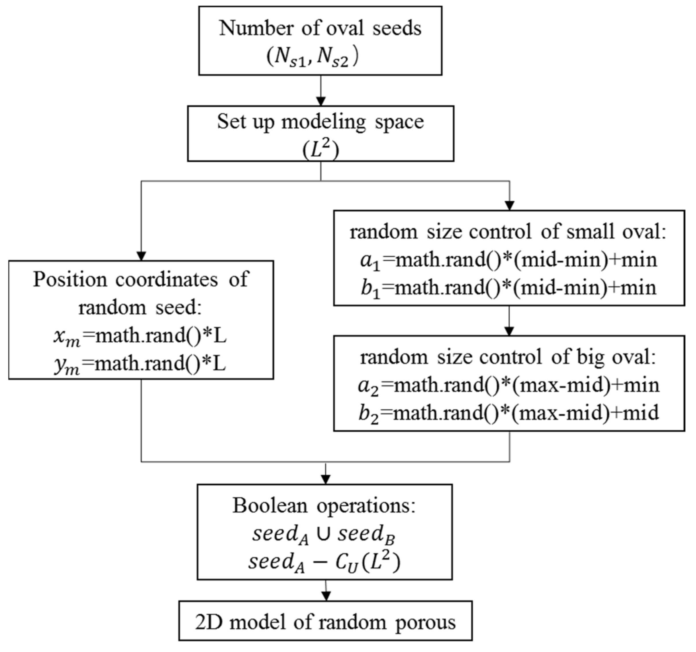
Based on the model theory of random seeds, the platform of COMSOL Multiphysics is used to carry out the modeling research of the two-dimensional cross-section with porous materials. The modeling research is completed by using the
Math.random function of the Java
® Language Specification and the algorithm flowchart is shown in
Figure 1.
First, the seed number
Ns is set and the modeling space
L2 (
L = 100 μm in this paper) is specified. In the literature [
19], the three-dimensional internal structure of the porous cage has been scanned and observed using X-ray CT technology, and it has been concluded that the small pores within the porous cage account for the majority of the pores, and the dense arrangement of these small pores is the main reason for the connectivity of the pores in porous oil containing cage. Therefore, the size of seeds is divided into two categories, including small-size seeds (the number was
Ns1) and large-size seeds (the number was
Ns2) which satisfies
Ns1 s> Ns2 based on the proportion (
P%) of raw material particles.
Because the return value of the Math. random() function is a random double-precision floating point number whose value is between 0.0 and 1.0, the size of the seed generated with this function will be in a fixed interval satisfying . At the same time, the random position coordinates of seeds are generated in the modeling space L2 by the Math.random() function. The random size of oval seeds is combined with the random position coordinates which further replicates the true formation process of pore structure in porous materials.
According to Equations (2) and (3) of random seeds modeling theory, the distribution of random seeds in the modeling space is checked, and Boolean operations are used to unite the overlapping graphics (
) and delete the beyond graphics
.
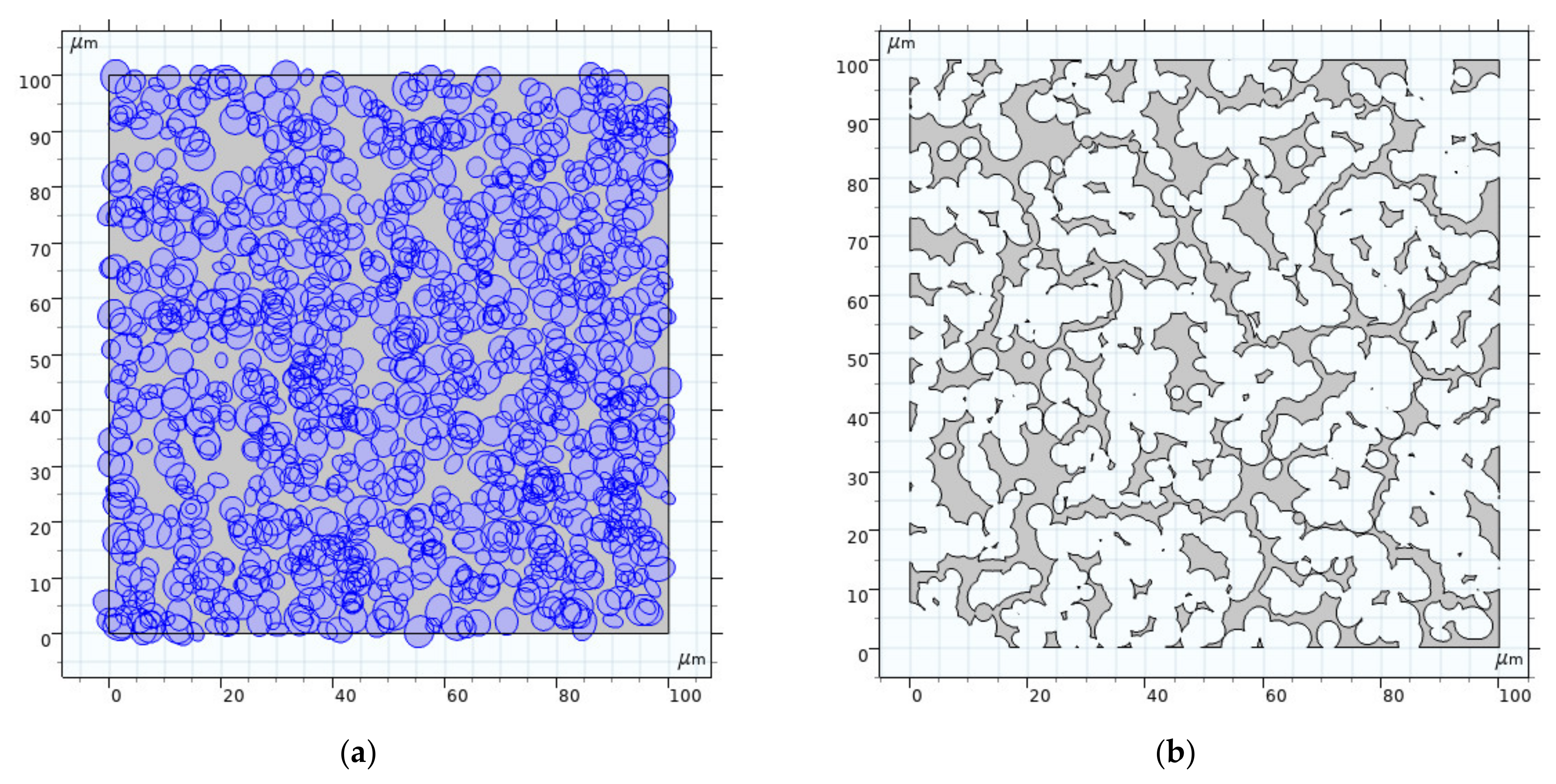
Figure 2 shows the formation process of porous model with an effective porosity of 0.1913 as an example, where (a) displays the accumulation drawing of oval seeds in the modeling space, and (b) is the forming drawing in which exhibits the subtraction of the accumulation of oval seeds from the modeling space.
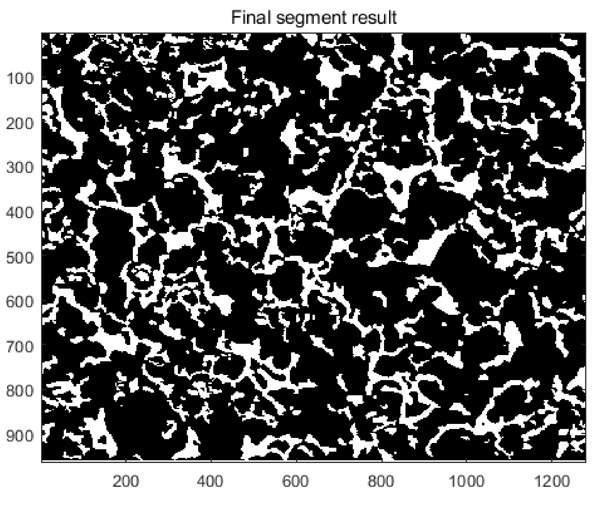
Figure 3 shows a binary graph of porous material, which is extracted from the scanning electron microscopy image of porous oil-containing cage. By comparing
Figure 3 and
Figure 2b, the morphological characteristics and distribution of the two figures are essentially the same, which shows the rationality of using the random seeds modeling theory to establish a two-dimensional local model of porous oil-containing cages.
4. Resistance Model of Micro-Scale Porous Media
The current theoretical models of flow resistance in the porous media feature a few problems, such as some empirical constants without physical meaning, limitation for micron/submicron structures, and the unspecified relationship between resistance and pore shape. Based on the established two-dimensional models of porous oil-containing cages with different porous parameters, this chapter develops a micro-scale resistance model for fluid flow in a micro-scale pores model of porous oil-containing cages based on the Hagen–Poiseuille equation.
4.1. Theoretical Derivation
Poiseuille [
21] experimented with animal blood in a round tube (diameter 30–140 μm), and it was found that the volume flow
Q per unit time was proportional to the pressure difference
(P1 –
P2) and the fourth power of tube radius
R, and was inversely proportional to the length
L of the tube. The well-known Hagen–Poiseuille equation was proposed as Equation (5).
This equation is applicable for the flow law in a micron-scale channel. In order to further research the lubrication mechanism of a porous oil-containing cage, the complex pore structure inside the porous medium is first simplified into a superposition model of multiple micro-scale circular tubes, and the flow resistance inside the porous medium is regarded as the sum of the resistance caused by each tube. Therefore, based on the Hagen–Poiseuille equation, the average flow velocity in the porous structure is derived from the flow rate and the cross-sectional area of the pipe, as shown in Equation (6).
where
A is the cross-sectional area of the circular tube,
ΔP represents the pressure difference between the outlet and the inlet,
μ is the dynamic viscosity of the fluid (a fluid property related to temperature),
r represents the radius of a uniform circular tube and
L represents the length of the circular tube.
Because of the intricate distribution of micro-scale pores in the porous oil-containing cage and the uneven cross-section of tubes, the “average hydraulic radius”
Rh is used to replace the radius
r of the circular tube. The hydraulic radius refers to the ratio of the overflow area of a certain water transmission section to the side length of water pipeline, as Equation (7).
where
Sall is the total cross-sectional area of fluid flow and
Zall is the total wetting circumference.
As the pore structures in the porous medium are curve channels instead of straight lines, the tortuosity parameter
τ = Lt /L is defined to correct the length of tube. From Equation (7), Equation (6) can be converted into Equation (8).
Further, according to the definition of hydraulic radius, Equation (9) can be derived.
where
Lt is the length of the channel, and
Vt is the overall volume of the porous medium, also known as the apparent volume.
The porosity of porous materials is divided into two types, namely, absolute porosity and effective porosity. Absolute porosity is the sum volume fraction of the connected pores and unconnected pores. From the perspective of fluid motion, only the interconnected pore space is meaningful, so the volume fraction composed of interconnected pores space is the effective porosity (such as
ε =
) in Equation (9). The porosity mentioned in this article is all the effective porosity, which is the ratio of the total volume
Vp of the connected pores to the overall volume
Vt, as in Formula (10):
Next,
a = (Zall × Lt)/Vt is defined, and then Equations (9) and (10) are considered, from which Equation (11) can be obtained.
where
a is the ratio of the total wetted area to the apparent volume of porous medium, which is a three-dimensional structural parameter in m
−1. In order to keep the unit consistent without changing its physical meaning,
a is converted into a two-dimensional structural parameter, which is the ratio of the total wetted perimeter to the apparent area of porous model, as shown in Equation (12).
where
Cp is the total wetted circumference, which is the total boundary length of the porous model, and
St is the total area of the two-dimensional cross-sectional porous model. From Equations (11) and (12),
Rh is substituted into Equation (8), the micro-scale resistance model of porous media is derived as Equation (13).
The flow velocity of the fluid through the micro-scale porous medium is very low, and it belongs to the range of peristaltic flow with a Reynolds number far smaller than 1. Therefore, the pressure drop generated by fluid unit through the pores that ignores inertial force loss is determined by the viscous drag loss, which is consistent with the actual theory. Besides, the pressure drop of the micro-scale resistance model has a linear relationship with the flow velocity, which is in accordance with Darcy’s law. It can be concluded from the above discussion that the micro-scale resistance model of porous media is reasonable.
4.2. Parameter Calculation
The micro-scale resistance model is a formula that includes parameters such as specific surface perimeter, effective porosity, tortuosity, fluid properties, fluid velocity and pressure drop. For the sake of further studying the lubrication mechanism in micro-scale porous media, the expression, composed of the parameters related to the porous structure and the fluid properties, is independently defined as a structural function
f(Cp,
St,
τ,
μ,
ε) in Formula (14).
Among them, Cp, St and ε are all determined by the geometric size and porous morphology of micro-scale pores model, μ is determined by the flow properties of the lubricating medium in the porous media, and τ is determined by the shape of the tubes in the porous model.
The way to obtain the tortuosity of porous media mainly includes extracting from 3D images, porosity derivation, and simulating fluid flow paths. In this paper, different methods of particle tracking and streamline acquisition are used to obtain the tortuosity of porous model.
4.2.1. Particle Tracking
The particle tracking module of COMSOL calculates the movement of particles in the fluid media to obtain the movement trajectory of particles. Taking the porous model with an effective porosity of 0.1534 as an example, the inlet boundary is set to uniformly release 100 solid particles with a diameter of 0.0001 μm, and the outlet boundary is set to wall condition of freezing. The particles in the entire porous medium domain have an upward movement speed. Additionally, the wall conditions are mixed diffuse reflection and specular reflection.
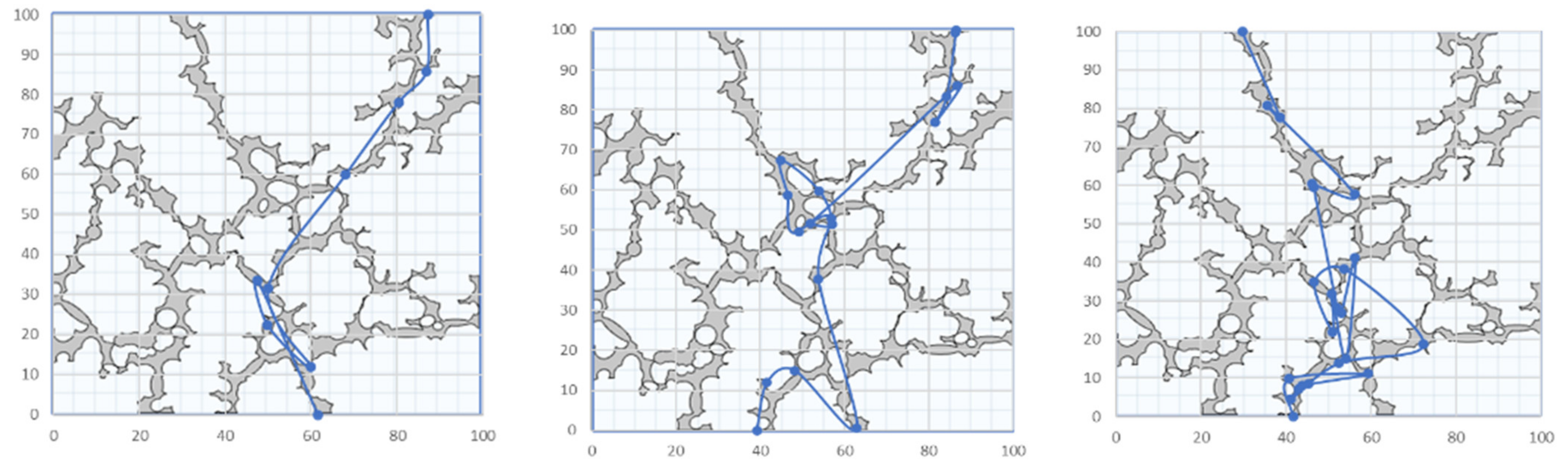
The particles release at the entrance and gradually move toward the exit boundary. However, due to the tortuous complexity of the porous model, the particles repeatedly collide with the wall during the movement and rebound. Few particles could overflow the porous medium domain. Therefore, not all particles have reached the exit boundary. In order to obtain the porous parameters, the simplest trajectory of three particles is selected from the particles reaching the exit boundary, as shown in
Figure 7.
The gray part in
Figure 7 is the porous structure, and the thick blue line is the particle trajectory. Although the obtained particle trajectory cannot characterize the morphological changes of the porous structure in some details, the general trend is consistent with the porous medium model, which can be approximated as the basic data of the porous structure. However, due to the particles repeatedly bouncing against the wall while moving in the pores, the calculated particle trajectory is clearly larger than the actual length of the porous channel, and it needs to be corrected before it is used.
4.2.2. Streamline Extraction Method
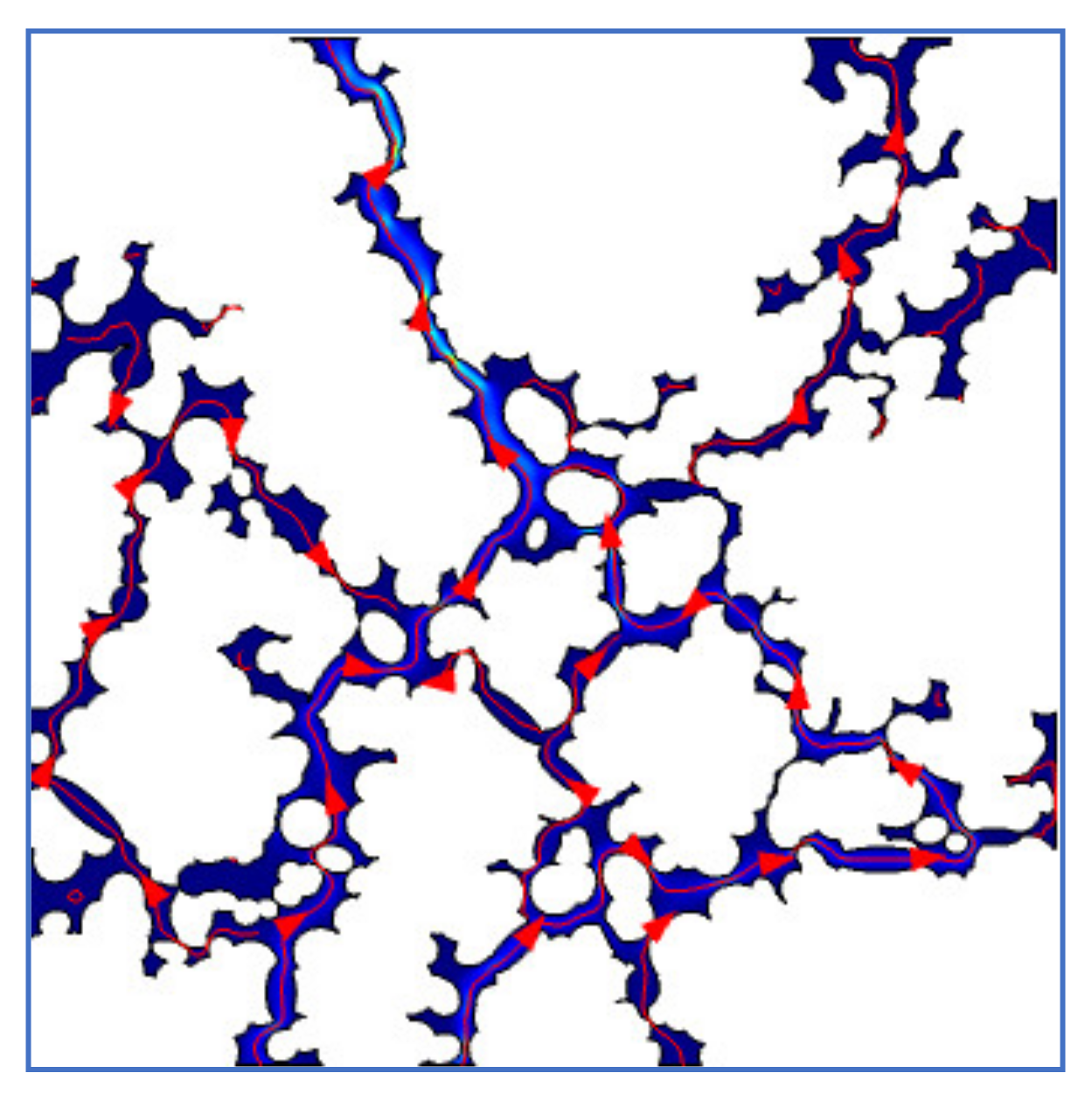
In order to accurately extract the porous channel length of micro-scale pores model, the streamline data are extracted based on the fluid flow path in the pore structure. As an example, the porous model with an effective porosity of 0.1534 is shown in
Figure 8, which is a streamlined diagram of fluid flow in the porous model.
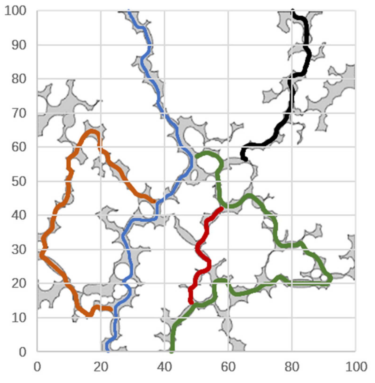
Figure 9 is the channel path diagram extracted from
Figure 8, where the different colors stand for the segmented channels. Compared with the particle tracking method, the extraction method of streamline data is more accurate, and the error between the extracted channels’ data and the channels’ shape of the pores structure is smaller. Therefore, this method is used in this paper to obtain the tortuosity parameters of micro-scale pore model.
Due to the large number of segmented channels,
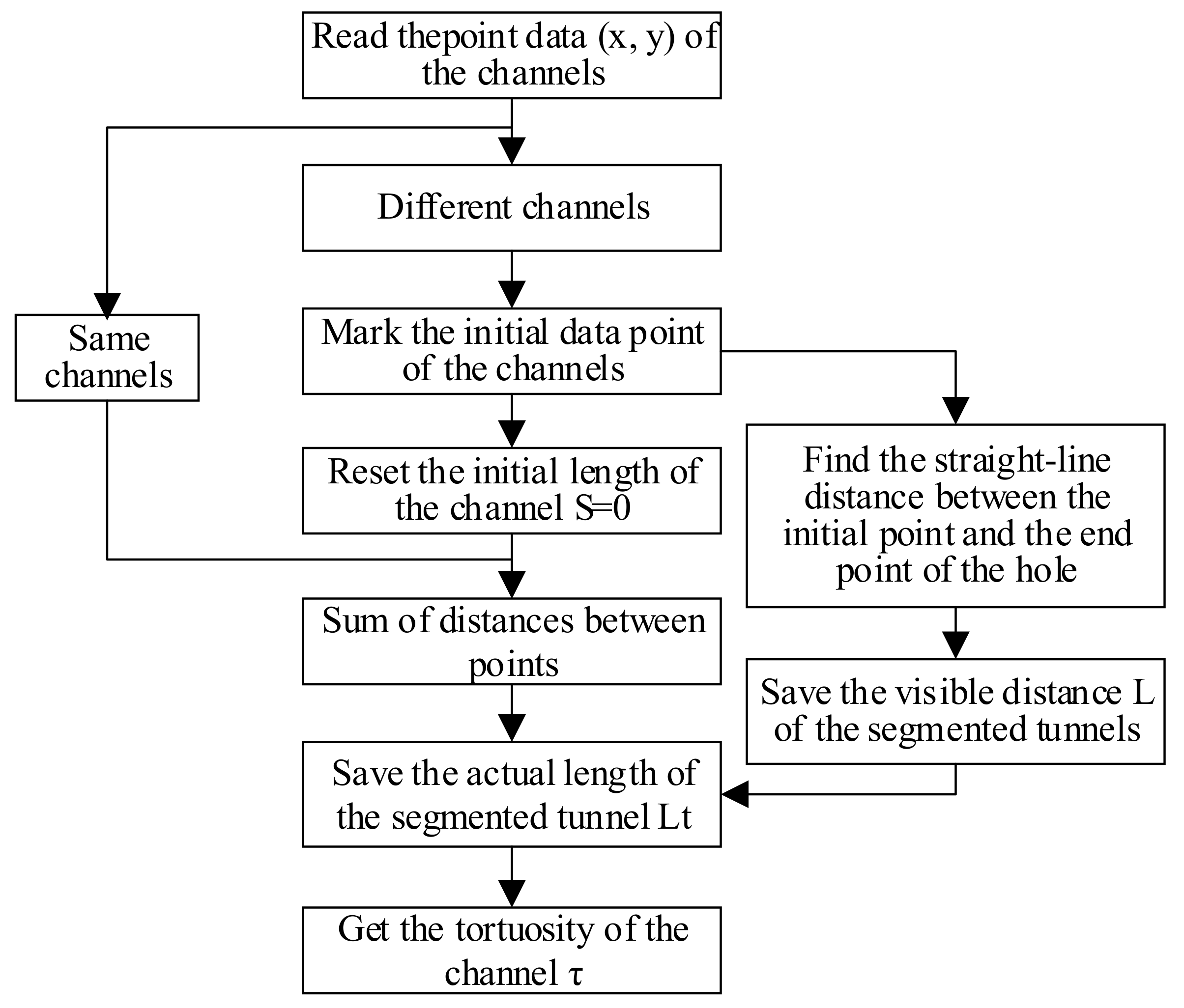
Figure 9 only shows the extraction diagram of four connected channels. Based on the channel data stored in the form of x- and y-coordinate data, a program to calculate the actual length and visible length of the channel is written. The algorithm principle is shown in
Figure 10.
Because there are enough data points for the segmented channels, the Pythagorean theorem is used to calculate the straight-line distance between the data points, which is regarded as an approximation length of the curved channel. Finally, the mean tortuosity of the segmented channels is applied to the structure formula in this paper.
The apparent area
St of porous model in this paper is the modeling space of 10,000 μm
2. When the temperature is at 25 °C, the dynamic viscosity of the selected lubricating oil is 0.54 Pa∙s. Other porous parameters are listed and the structure function value
f is calculated according to Formula (14), as shown in
Table 1. The
f is the structure function which is related to the geometric size of micro-scale porous model, the flow properties of the lubricating medium in the porous model, and morphological characteristics of pore structure. It can be seen that there are no empirical coefficients without physical significance in the above equations, which is of great significance for the flow mechanism of micro-scale porous media.


