Abstract
An investigation of mechanical properties of Ti6Al4V produced by additive manufacturing (AM) in the as-printed condition have been conducted and compared with wrought alloys. The AM samples were built by Selective Laser Melting (SLM) and Electron Beam Melting (EBM) in 0°, 45° and 90°—relative to horizontal direction. Similarly, the wrought samples were also cut and tested in the same directions relative to the plate rolling direction. The microstructures of the samples were significantly different on all samples. α′ martensite was observed on the SLM, acicular α on EBM and combination of both on the wrought alloy. EBM samples had higher surface roughness (Ra) compared with both SLM and wrought alloy. SLM samples were comparatively harder than wrought alloy and EBM. Tensile strength of the wrought alloy was higher in all directions except for 45°, where SLM samples showed higher strength than both EBM and wrought alloy on that direction. The ductility of the wrought alloy was consistently higher than both SLM and EBM indicated by clear necking feature on the wrought alloy samples. Dimples were observed on all fracture surfaces.
1. Introduction
Additive manufacturing (AM) has gained huge popularity in the last decade or so. Its ability to produce complex shapes, reduce the number of parts, reduce the material waste, etc. have been the main drive of this technology. According to ASTM, AM can be devided into seven categories including (i) VAT photopolymerisation, (ii) material jetting, (iii) binder jetting, (iv) sheet lamination, (v) material extrusion, (vi) powder bed fusion (PBF), and (vii) directed energy deposition (DED). For metallic materials, Directed Energy Deposition (DED) and Powder Bed Fusion (PBF) are the only options. Within the PBF methods, electron beam melting (EBM) and selective laser melting (SLM) are two common methods to produce metallic parts where the powder is melted and fused by either electron beam or laser beam. SLM materal is generally stronger and less ductile compared with EBM [1]. SLM produces martensite due to ambient temperature manufacturing bed with fast cooling, while EBM produces alpha lath (alpha-beta) structure due to the powder bed being maintained at much higher temperature for manufacturing (approximately 700 °C for Ti6Al4V). Manufacturing in SLM is typically carried out under inert gas, while EBM is performed in vacuum athmosphere with powder bed heated to above stress relieving temperature, hence, minimising the residual stresses caused during solidification [1,2]. Ductility of SLM-ed parts can be improved by HIP or heat treatment. The details of the SLM and EBM processes have been described by various authors [3,4].
As far as the metallic material is concerned, some of the metals/alloys which are readily used for AM including stainless steels (SS316 and SS304), nickel-based alloys (Inconel 718/625), aluminium alloys (AlSi10Mg, Scalmalloy), Co-Cr alloy, tool steels (H13), and titanium (Ti6Al4V and CP Ti). The above metallic AM has been reviewed by a few authors [5,6,7,8,9].
More specifically, evaluation of mechanical properties of AM of Ti6Al4V produced by EBM and SLM have been reported separately by various authors [10,11,12,13,14,15,16,17,18,19,20,21]. Limited studies have been conducted to compare SLM and EBM [22,23,24,25,26,27,28], and there has been even more limited work to directly compare the AM materials with wrought alloys. The reported results varied. In general, however, SLM produces samples with higher strength (lower ductility), higher fatigue strength compared to EBM products due to the faster cooling rates on the former [24,25,26,27,28]. Gao et.al. specifically reported that the higher yield and tensile strengths of samples produced by SLM compared with those of EBM due to the presence of α′ martensite on the former. They also reported SLM and EBM samples show comparable ductility, fatigue strength and hardness [26].
EBM and SLM are the two most common methods to produce metallic componets, therefore, this investigation was dedicated to focus on the Ti6Al4V samples manufactured by EBM and SLM, and compared to the traditional wrought alloys. To the best knowledge of the authors, there has been no publications on a comprehensive comparison between EBM, SLM and wrought alloys comparing various build directions, hence, the novelty of this paper. It presents a comparison of surface roughness, microsctructures and mechanical properties of samples manufactured by EBM and SLM built in the 0°, 45° and 90° in the as-printed conditions, compared with those of wrought alloys (annealed and solution treated and aged—STA conditions) also in three different directions.
2. Experimental Procedures
2.1. Materials and Sample Directions
The material investigated in this study was Ti-6Al-4V (Ti64) manufactured by three different processes, i.e., (i) wrought and rolled sheet, hereafter wrought (ii) electron beam melting-EBM, and (iii) selective laser melting-SLM with a thickness of around 2 mm (Figure 1). For the wrought alloy, the samples were cut in 0° (longitudinal/horizontal), 45° and 90° (transverse), while the EBM and SLM samples were built also in the same directions (Figure 1). The particle size of SLM and EBM powders were 5–50 μm and 50–150 μm, respectively. The powder for EBM was provided by Arcam (AP&C) Co. (ARCAM, Mölndal Municipality, Gothenburg, Sweden), while the SLM powder was provided by Pyrogenesis Canada Inc. (Pyrogenesis, Montréal, QC, Canada).
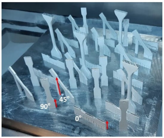
Figure 1.
Diagram showing samples after printing by SLM (similar printing diagram was reported for EBM). Note: build orientation is shown by the red arrows.
The EBM samples were printed using Arcam Q10plus 5.0 themes with a layer thickness of 50 μm, speed function of 64, line offset of 0.2 mm and a current of 30 mA which would give an energy density of around 94 J/mm3. The SLM samples were printed using EOS GmbH, EOSINT M270 machine using a rotating stripe pattern. Parameters of 190 W laser power, scanning velocity of 1200 mm/s, hatch distance of 100 μm, and layer thickness of around 30 μm were used, resulting in a calculated energy density of 53 J/mm3.
The densities of the printed samples were measured by the Archimedes methods.
2.2. Surface Roughness
Surface roughness, Ra, was measured according to layer direction using Taylor Hobson Ultra 2006 version software. An average of three readings was taken per sample.
2.3. Metallography and Microscopy
Cross-sectional metallography samples were prepared from each material. The samples were ground were ground using SiC papers with grit size from 100 to 2400, and were polished up to 0.3 μm diamond paste. A diluted hydrogen peroxide (30%) was used at the final stage of polishing for a better response to ecthing. The samples were then etched with Kroll’s reagent (3 mL HF + 6 mL HNO3 + 100 mL water). An optical microcope (Olympus PME3, Tokyo, Japan), was employed to observed the microctructure. The microscope is equipped with an image analysis (ImageJ software, version 1.51, NIH, Bethesda, MD, USA). A scanning electron microscope (Hitachi SU-70 Schottky, Marunouchi, Chiyoda-ku, Tokyo, Japan) was employed to examine the surface morphology of the as-printed samples and the fracture surfaces of the tensile tested samples.
2.4. Mechanical Testing
Vicker’s hardness tests were performed on the metallographically-prepared samples using a load of 300 g and a dwell time of 10 s. A minimum of three hardness indentations were made for each sample.
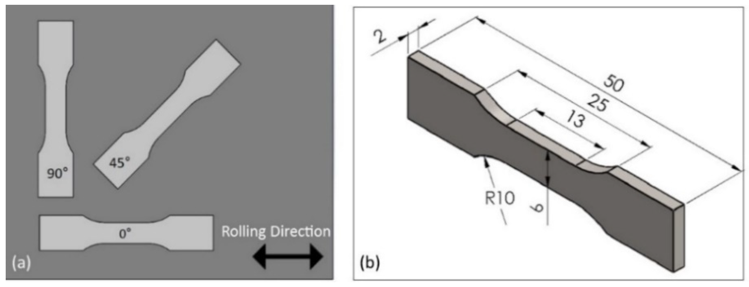
Figure 2 shows the schematic drawings of a dog-bone sample for tensile testing. The samples built by SLM and EBM are shown in Figure 1 while the wrought samples, they were cut from a rolled sheet, also in three different directions as indicated on Section 2.1. Tensile tests were conducted on Shimadzu AG-X Plus 300KN load frame with pneumatic grips and with a speed of 3 mm/min. The machine was equipped with a Correlated Solution 3D DIC system with a couple of 2.3MP cameras. This non-contact technique was employed to measure both the overall strains as well as the local strains at the fracture locations. Prior to the real tensile testing, some trials were conducted at a speed of 0.15 mm/min as suggested by ASTM, but the time required to test a sample was significantly too long. In addition, there were no significant differences observed in terms of physical appearance and tensile data with those tested at 3 mm/min, therefore, all the samples were tested at a speed of 3 mm/min. The post processing of the DIC was also done by the Correlated Solution VIC3D.

Figure 2.
(a) Dog-bone sample orientation for the wrought alloy and (b) dimensions for all samples (in mm).
3. Results and Discussion
3.1. Chemical Composition and Densities
The chemical composition of the samples is presented on Table 1.

Table 1.
Chemical composition of the titanium alloys (wt.%).
The relative density of the samples were 96–98% for SLM, 96–97% EBM and >99% for the sheet wrought alloy. These are equal to the density of 4.25–4.34 g/cm3, assuming 100% is 4.432 g/cm3. Note that porosity is defined as the volume fraction of pores. It is expressed as p = 1 − ρ/ρT, where ρ is the sample density and ρT is the theoretical density of the substance [29,30]. The theoretical density of Ti-6Al-4V was 4432 kg.m−3 or 4.432 g/cm3 as indicated above.
3.2. Surface Morphology and Hardness
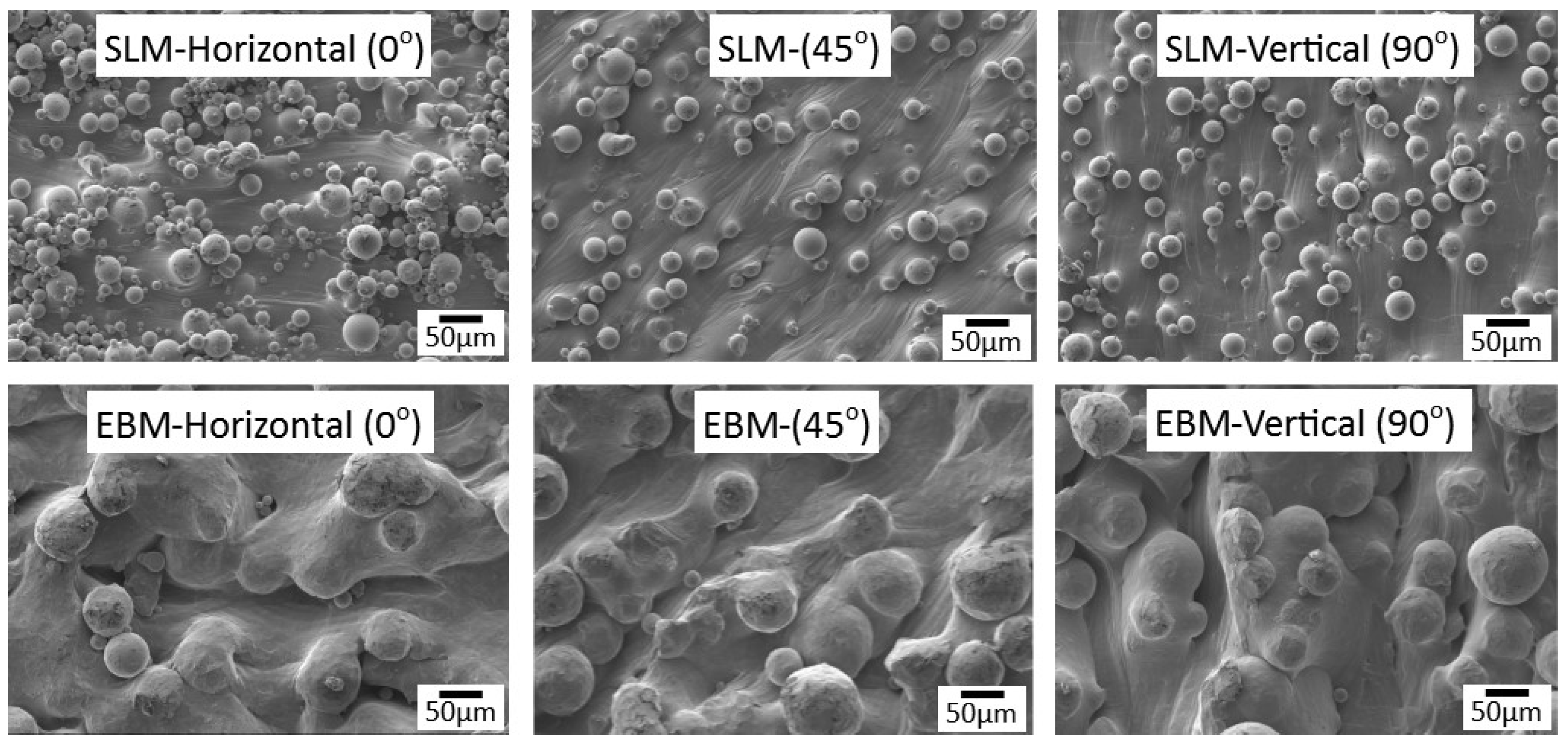
Figure 3 shows the surface morphology of the printed samples. They looked similar to what have been reported previously [27,28]. However, with the reported AM samples, they did not show any indication of surface cracking as reported elsewhere [27]. It is noticeable that the particle size of SLM was smaller than those of EBM, i.e., 10–40 µm and 20–70 µm, respectively. The size of SLM particle was comparable to those used by other researchers, e.g., 5–50 µm [20] and 25–45 µm [28,29,30,31,32,33]. Other works with EBM indicated the particle size of around 82 µm [15], 77 µm [28], 60–70 µm [34,35]. According to Froes [1] the desired powder size of SLM is 20–75 µm, and 40–150 µm for EBM. The main reason why EBM uses larger particles is to keep them stick to the building platform instead of “flying around” (dusting effect) inside the chamber during the printing process [26]. Small size particles may cause particles spreading in the chamber due to electrostatic discharge [32]. From Figure 3, it is a also apparent that all surfaces contained partially melted particles which are attached to the surface on samples from both AM processes which may have contributed to the surface roughness.

Figure 3.
Surface morphology of samples built by SLM and EBM in various direction.
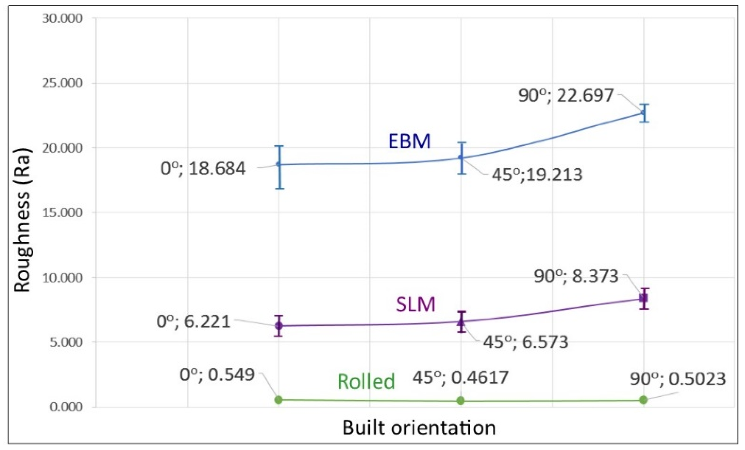
Comparing the roughness of the AM samples in these experiments with other reports, they were smoother than those reported by others as described below. Figure 4 shows the surface roughness of the samples in this investigation was 6–8 μm, 18–23 μm and 0.45–0.6 μm for SLM, EBM and wrought samples, respectively. The relatively rougher surface on EBM samples is likely due to its larger particle size compared with that of SLM, particularly those of the partially melted particles which are still intact on the surface. This is consistent with what was reported by Zhao et al. [28]. A number of articles reported similar surface roughness for SLM, e.g., 30–40 [19,27]. Meanwhile, Song et al., using particle size of around 10–31 µm, claimed that with the correct parameters i.e., 110 W and a scanning speed of 0.4 m/s, a smooth surface of Ti6Al4V can be fabricated with SLM due to the continuous melting effect [33]. For EBM, surface roughness has been reported to be around 46 µm [18], 70 µm [27], and up to 130 µm [34]. Furthermore, Fousova et al. [27] indicated that the larger size of particles in EBM increased the unevennes of the surface. Froes [1] suggested that SLM parts may have surface roughness of about 10–25 µm, while EBM could be as high as 50 µm which is as rough as sand casting products. Apart from the material’s feedstock, i.e., size of particle and improper melting, the surface roughness may also be associated with post processing such as CNC machined, scan path strategy and powder morphology [6,36]. For certain applications such as implants, rough surfaces are sometimes preferred to facilitate bone ingrowth.

Figure 4.
Surface roughness, Ra, values (in µm) of EBM and SLM samples built in different orientations. Note: the wrought sample was rolled in longitudinal direction and were cut in 0° (longitudinal/horizontal), 45° and 90° (transverse) directions.
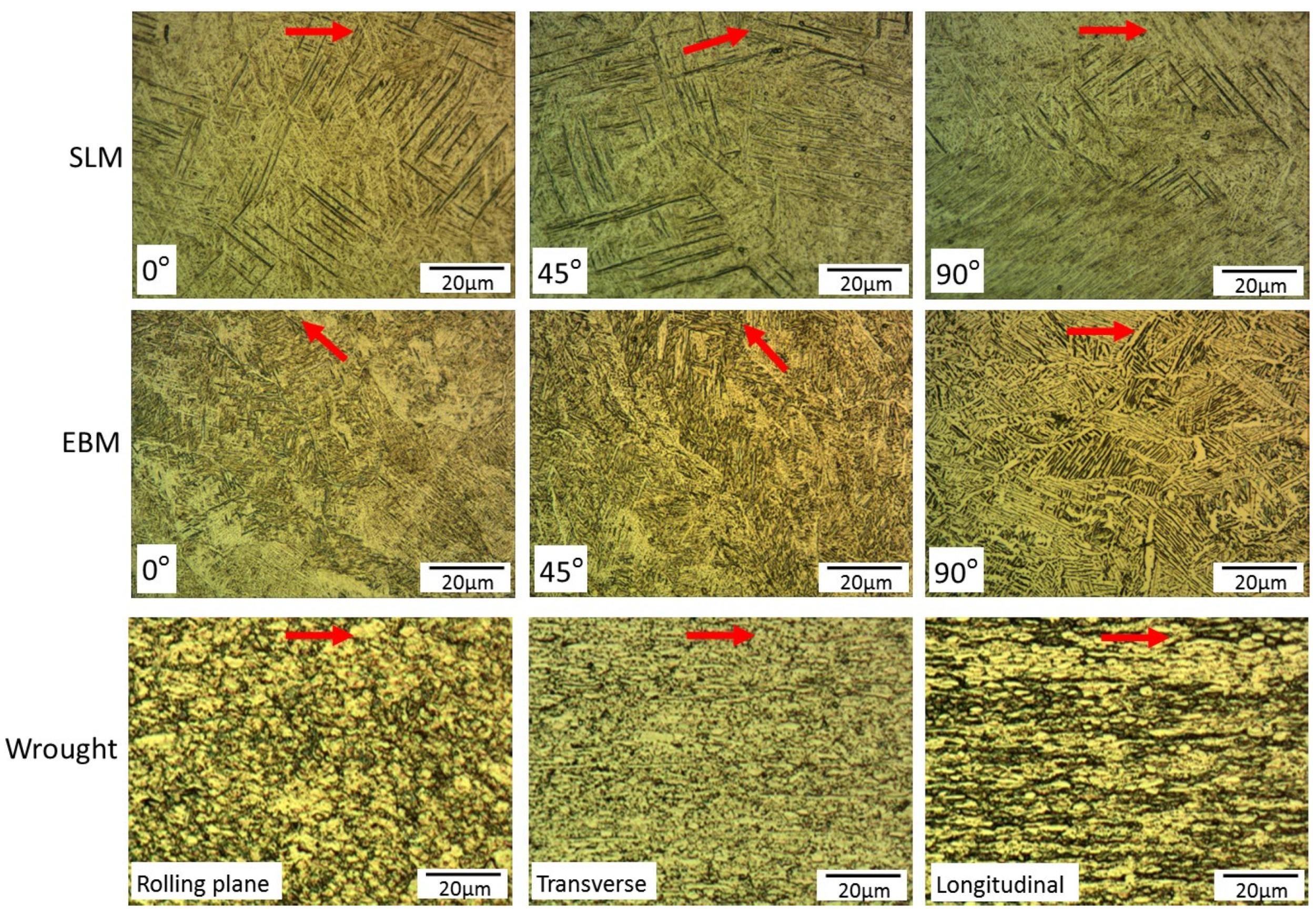
The microstructure of SLM showed a mixture of α’ martensite and acicular α, while the EBM samples had acicular α and prior β grain boundaries (Figure 5). These findings are consistent with what has been reported previously [7,8,9,10,11,12,20,24,27,28]. This is due to the nature of the processes, i.e., SLM samples were processed in inert gas athmosphere (argon) couple with high scanning speeds and high thermal gradients leading to fast cooling rates; while EBM was done in vacuum where the powder bed and the surrounding powder particles are heated up to 700 °C, thus lowering the temperature gradients, hence, a lower cooling rate than SLM [24]. It is well known that α′ martensite is main strengthening phase in Ti6Al4V titanium alloys, but is less ductile than acicular α phase [35,36]. Therefore, following printing, SLM samples are often heat treated to improve its ductility [1,21]. The wrought samples, showed traces of rolling effect as indicated by relatively elongated (pancake-shaped) grains on the longitudinal plane sample. The structure contained both α′ martensite and acicular α. The difference in the microstructures, coupled with anisotropy associated the build direction [6,37,38,39] certainly play a role on the hardness variations as reported below.

Figure 5.
Optical micrographs of SLM, EBM and wrought samples. Note: build orientation for SLM and EBM (and rolling direction—wrought alloys) are indicated by the red arrows.
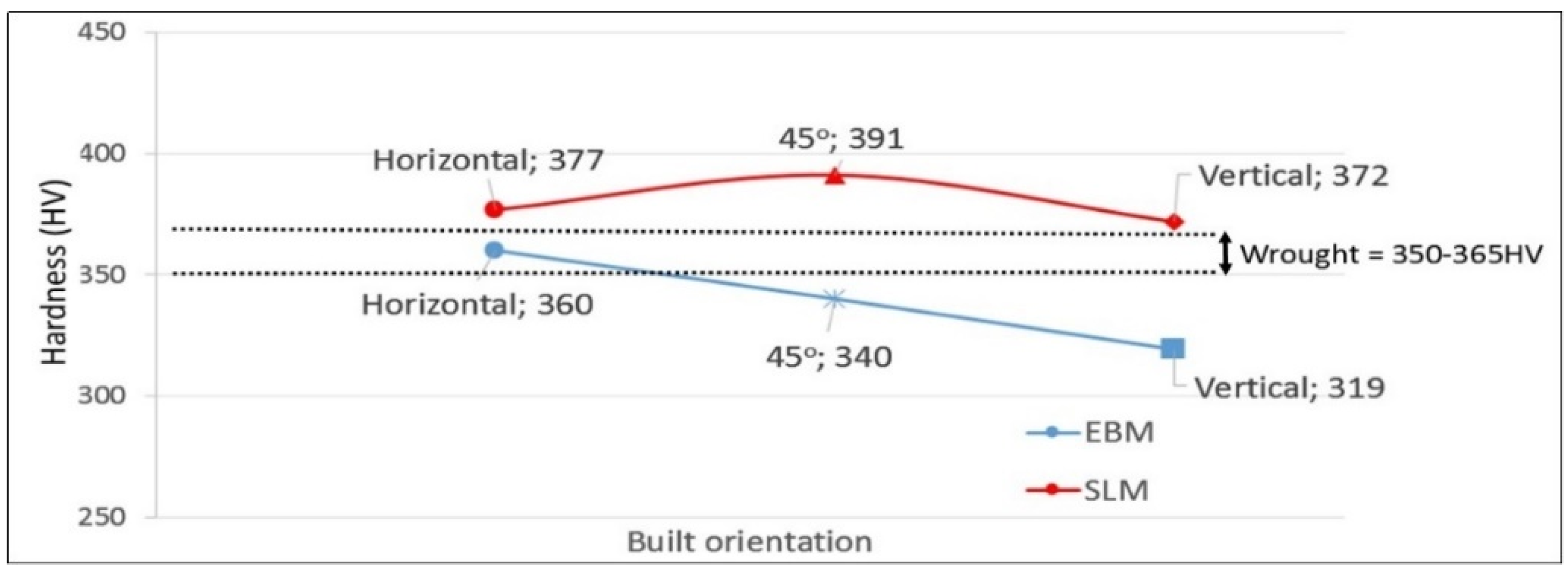
SLM hardness ranged from 372 to 391 HV (Table 2 and Figure 6). Thijs et al. [20] reported hardness values between 350 and 520 HV, and suggested the high hardness values were obtained at slower scanning speed. For our exeriments, the samples were produced at a scanning speed of 1200 mm/s, while in Thijs et al. experiments, the scan speeds were between 50 and 200 mm/s [20].
Table 2.
Average hardness (HV300) for AM samples *.

Figure 6.
Hardness values (HV300) of EBM and SLM samples built in different orientations. Hardness values of wrought samples are indicated.
For EBM, our samples showed slightly lower hardness compared with those of SLM, i.e., 319–360 HV (Table 2 and Figure 6). This hardness range is comparable to those reported elsewhere. Murr et al. [11] reported hardness around 360-410 HV, Chern et al. [15] showed a range of 304–388 HV, Karlsson et al. [17] 300–420 HV; and Galarraga et al. [18], and Hrabe and Quinn [33] reported 360–380 HV, depending on the built direction and the parameters used. Hardness of the wrought samples were between the those of EBM and SLM, and that explained the mixture of the presence of α′ martensite and acicular α on the sample.
3.3. Tensile Tests and Fractography
In general, for the AM samples, SLM showed a slight higher strength in all built directions than those of EBM but both had comparable ductility. A summary by Lewandowski and Seifi [29] strongly suggested that samples produced by SLM are stronger than those of EBM which is in agreement with our results. Tensile strengths are mainly in the range of 800–1000 MPa and 900–1200 MPa for EBM and SLM, respectively [5], although He et al. [40] claimed to have achieved a tensile strength of SLM up to 1261 MPa.
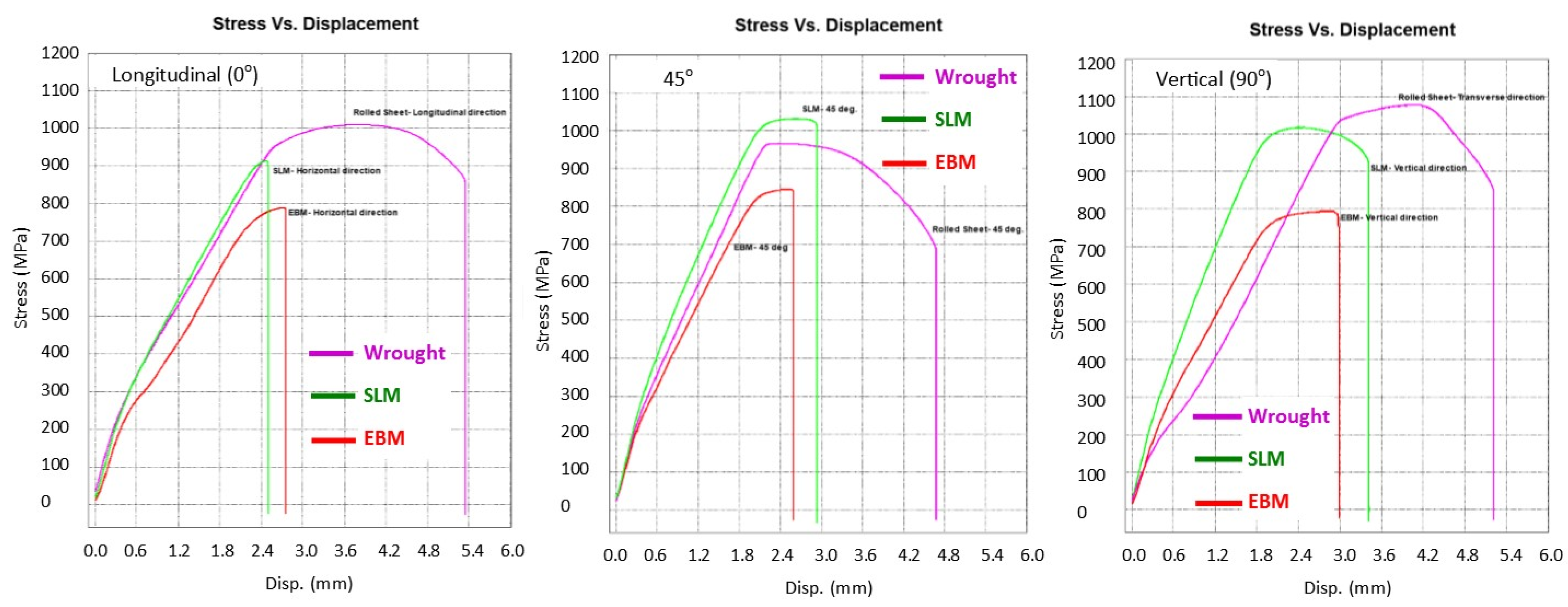
Figure 7 presents the stress-strain curves of the samples from SLM, EBM and wrought alloys in all three directions/build orientations, i.e., 0°, 45° and 90° where the effect on strengths is fairly obvious. In the case of SLM, the built direction affect both σy and σu where 45° direction being the strongest and transverse (0°) being the weakest and least ductile. This is in agreement with what was reported by Ren et al. [13] and Agius et al. [41]. It is believed that that the residual stress and the pore distribution was responsible for this (note that following hot isostatic pressing—HIP, the difference was eliminated [9,13]). For EBM materials, again the 45° showed higher strengths compared with 0° and 90° directions. Although it may not be significant but the elongation was lower in 0° compared with other directions for both AM-produced materials. However, a different effect of direction was observed on the wrought materials. The strengths were the highest on the 90° followed by 0° and 45°. This is understandable as the direction samples were pulled normal to the grain orientation. A study by Vilaro et al. [21] showed similar finding on the SLM-built samples, where transverse direction showed a slight higher strength (around 4%) compared to the longitudinal direction. The elongation of wrought samples were nearly double the elongation of both SLM and/or EBM with the longitudinal (0°) direction showed highest ductility than all other samples (Figure 7 and Table 3). Such variations in the mechanical properties on both the AM-built specimens and the wrought alloys was arguably associated with the anisotropy of the samples as a result from printing/scanning or from rolling directions for AM and wrought alloys, respectively [6,37,38,39]. It should also be born in mind that the AM samples had significantly higher surface roughness than wrought alloys, so the comparative tensile results combined the effects of bulk material and surface differences.

Figure 7.
Stress vs. displacement diagrams of samples in 0°, 45° and 90° directions.
Table 3.
Tensile testing results (three samples were tested for each material in each direction).
With regards to the stiffness, the slope in the elastic region on the stress vs. displacement graph showed that SLM had a slightly higher stiffness than both EBM and wrought samples in all three orientations (Figure 7).
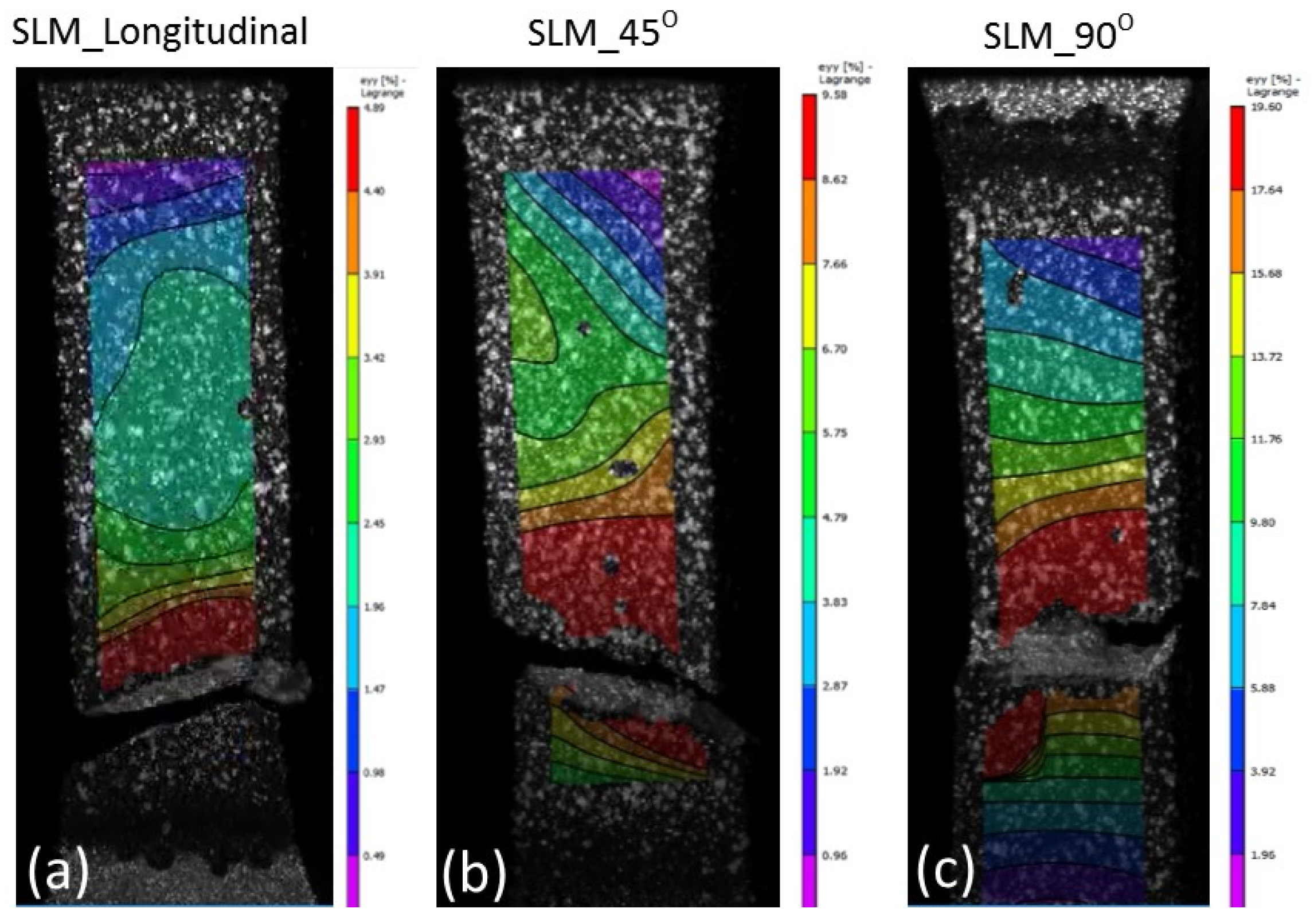
The results from tensile testing represented by the digital image corelation (DIC) analysis showed a clear indication that wrought materials had more ductility compared with AM materials (Figure 7, Figure 8, Figure 9 and Figure 10). EBM samples had elongation of up to 7%, while SLM samples reached up to 10% and wrought samples experienced elongation up to 15% before fracture. The relatively lower elongation on EBM samples could be related to the large grains compared with those of SLM and wrought alloys. While the higher elongation particularly observed on the 90° of SLM samples is, arguably, due to the favourable build orientation (Figure 1) coupled with smaller grains (Figure 3, Figure 4 and Figure 5). The wrought alloys showed highest elongation in all directions due to their uniform grain size and more dense (no pores) as it has gone through rolling process.

Figure 8.
DIC images showing all samples at fracture states of SLM material. Note the maximum elongations at fracture locations were about (a) 5%, (b) 10% and (c) 19.5% on the 0°, 45° and 90°, respectively.

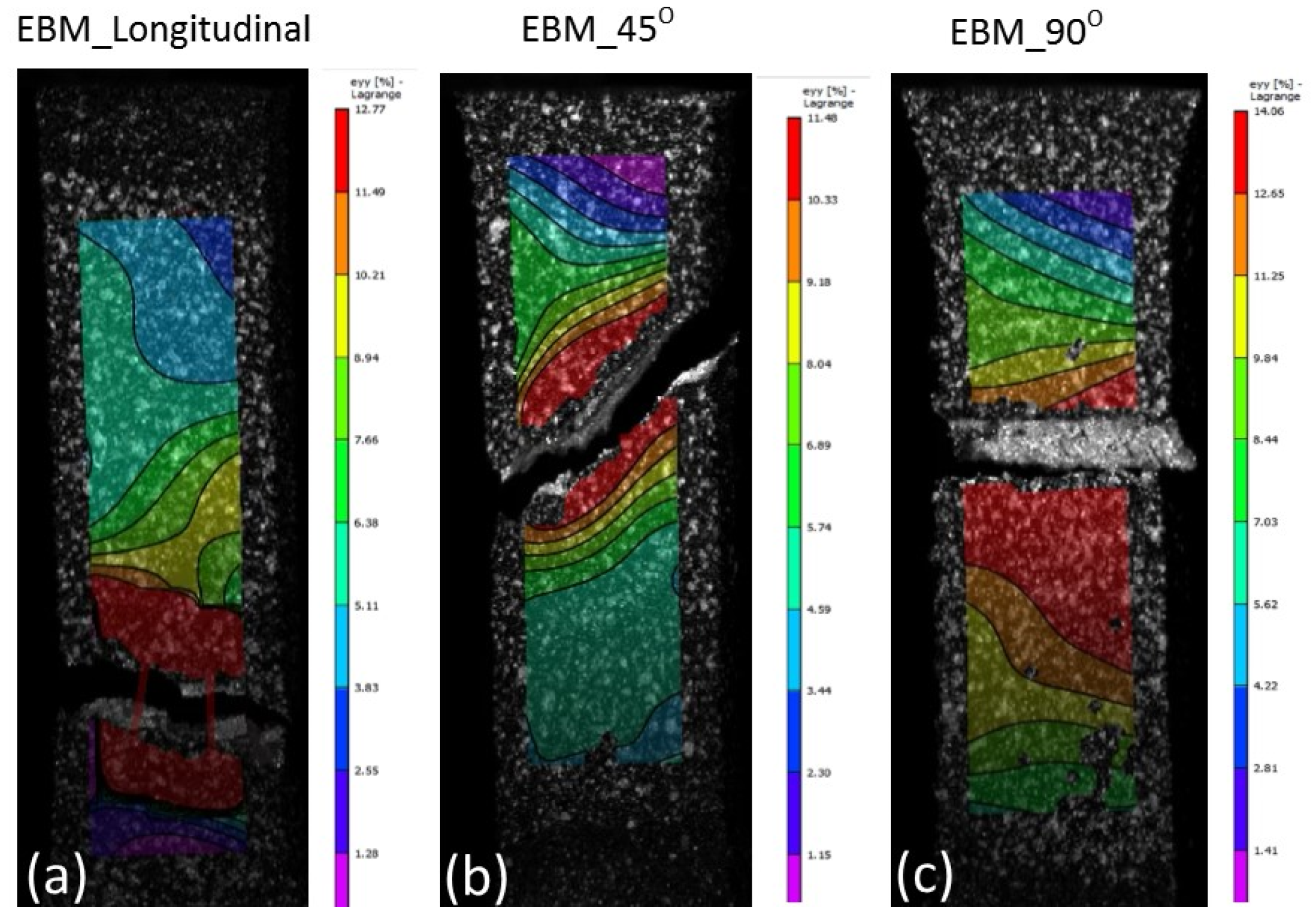
Figure 9.
DIC images showing all samples at fracture states of EBM material. Note the maximum elongations at fracture locations were about (a) 13%, (b) 12% and (c) 14% on the 0°, 45° and 90°, respectively.

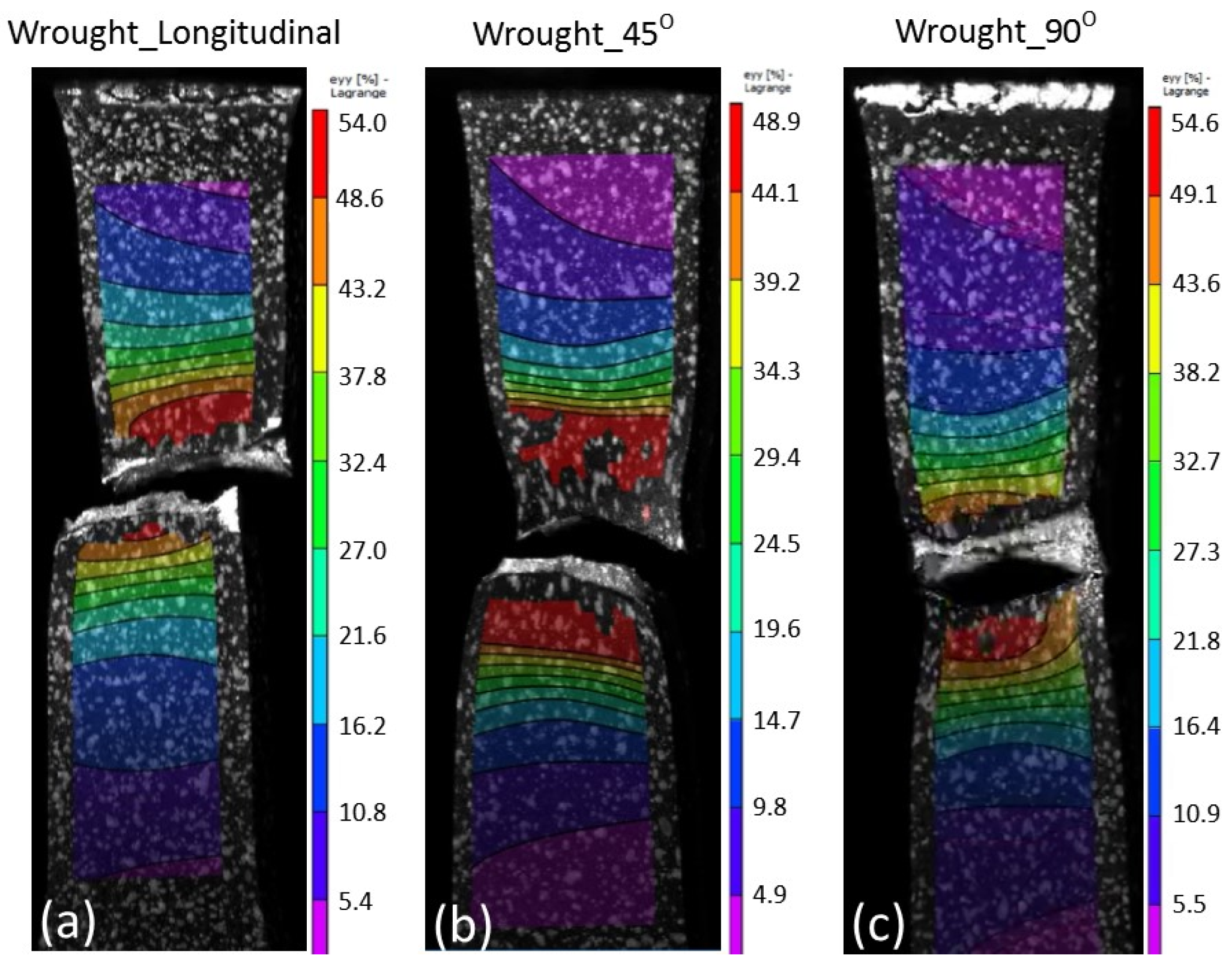
Figure 10.
DIC images showing all samples at fracture states of wrought material. Note the maximum elongations at fracture locations were about (a) 54%, (b) 50% and (c) 54.5% on the 0°, 45° and 90°, respectively.
From the DIC images it is also obvious that the highest strain took place in the reduced sections area, hence, fracture locations. The local strain where fracture took place are indicated in red, and it showed somewhat higher than the total elongation. While the AM samples showed negligible necking (Figure 8 and Figure 9), the wrought samples (Figure 10) clearly showed noticeable necking mechanism prior to fracture, i.e., up to 54% compared to 19.5% and 14% maximum for SLM and EBM samples, respectively.
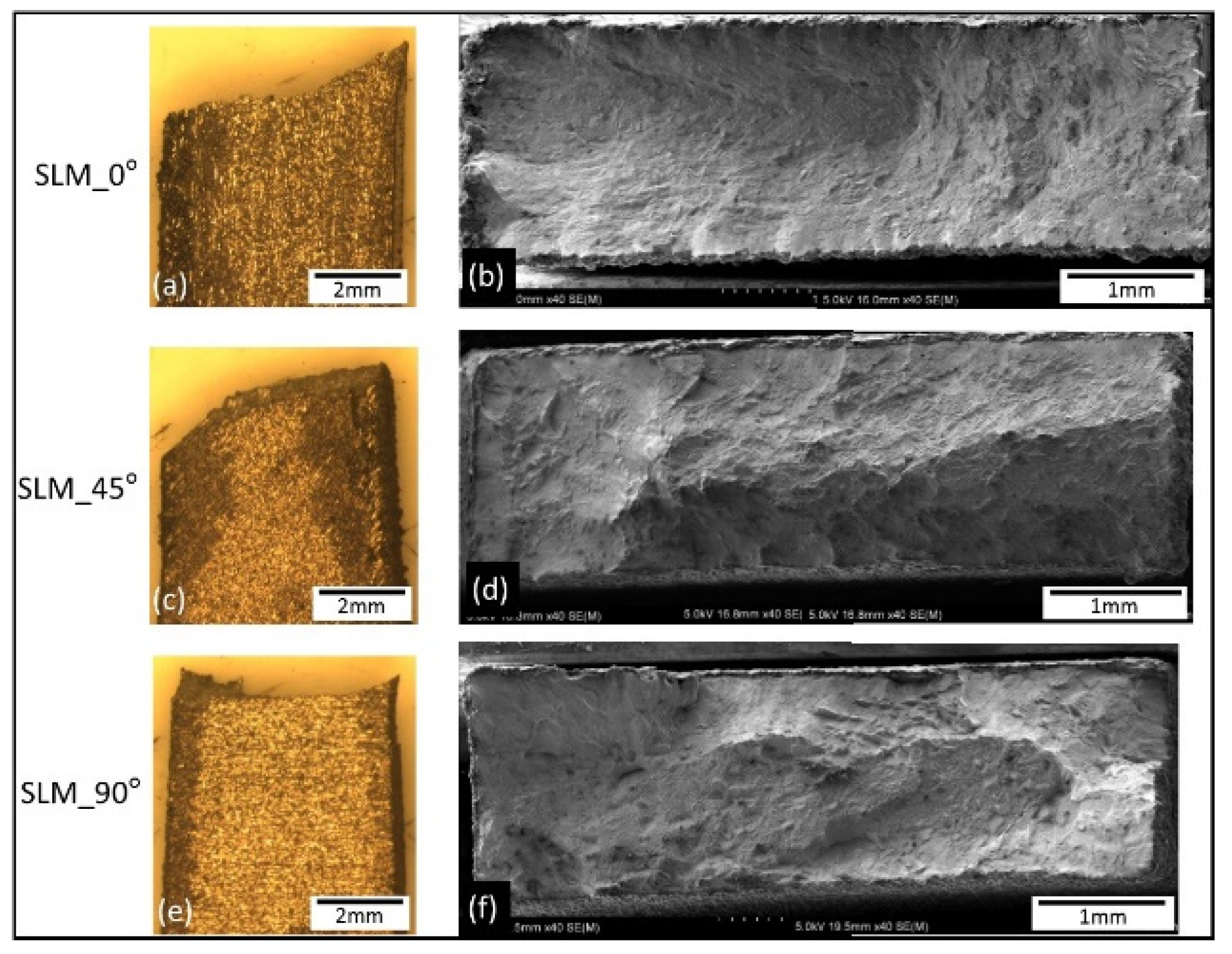
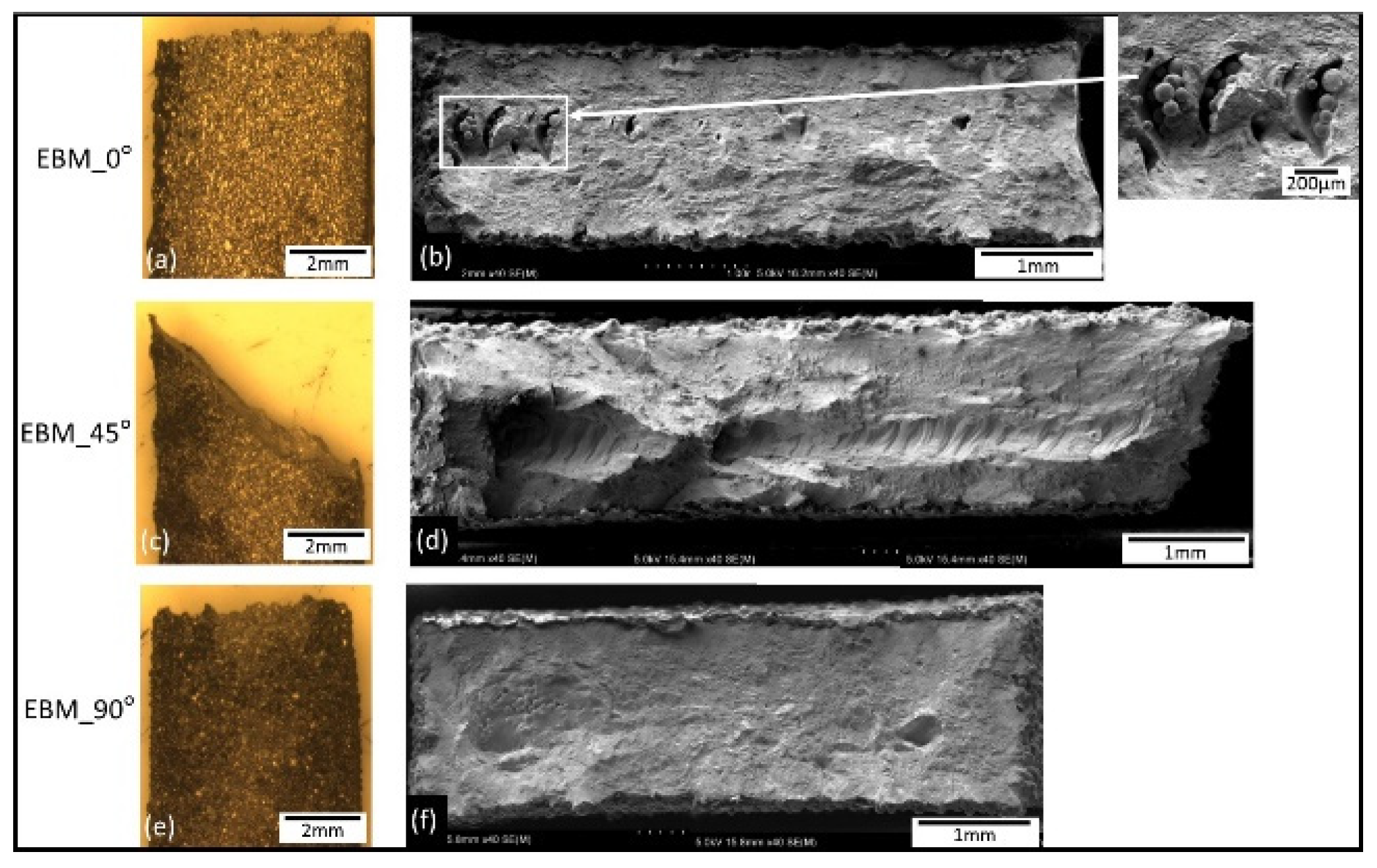
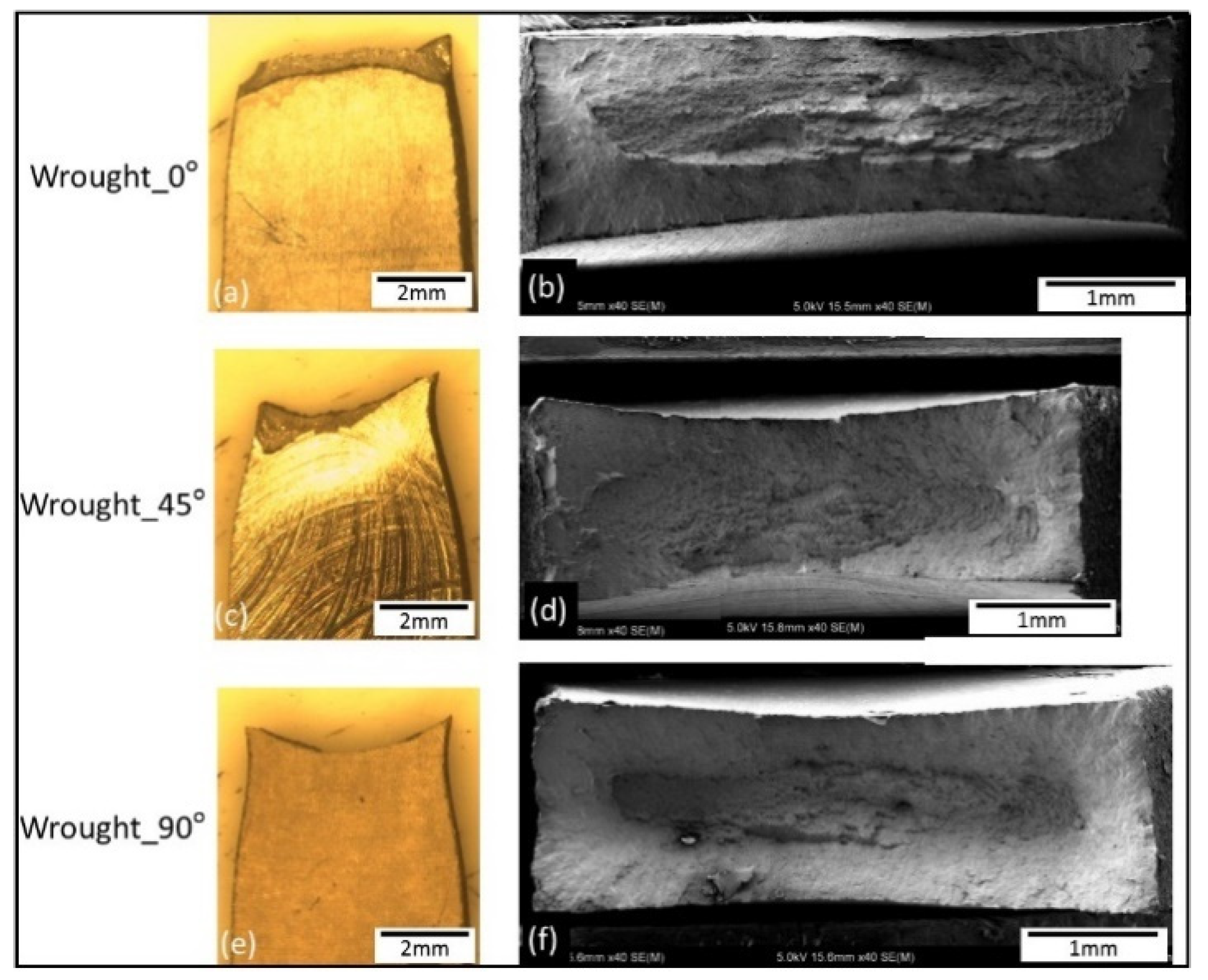
Macrographs of the fracture surfaces from tensile test samples are shown in Figure 11, Figure 12 and Figure 13. Both SLM and EBM samples showed either flat or 45° angle with fairly little (or no) evidence of necking, while the wrought samples showed significant necking prior to fracture where a clear cup and cone shape can be seen on Figure 13.

Figure 11.
Macrographs showing side view of the tensile tested samples (a,c,e) and low magnification images of the fracture surfaces of the SLM samples (b,d,f).

Figure 12.
Macrographs showing side view of the tensile tested samples (a,c,e) and low magnification images of the fracture surfaces of the EBM samples (b,d,f). Note the un-melted particles on EBM_0° also reported in [16,20,27].

Figure 13.
Macrographs showing side view of the tensile tested samples (a,c,e) and low magnification images of the fracture surfaces of the wrought alloy (b,d,f).
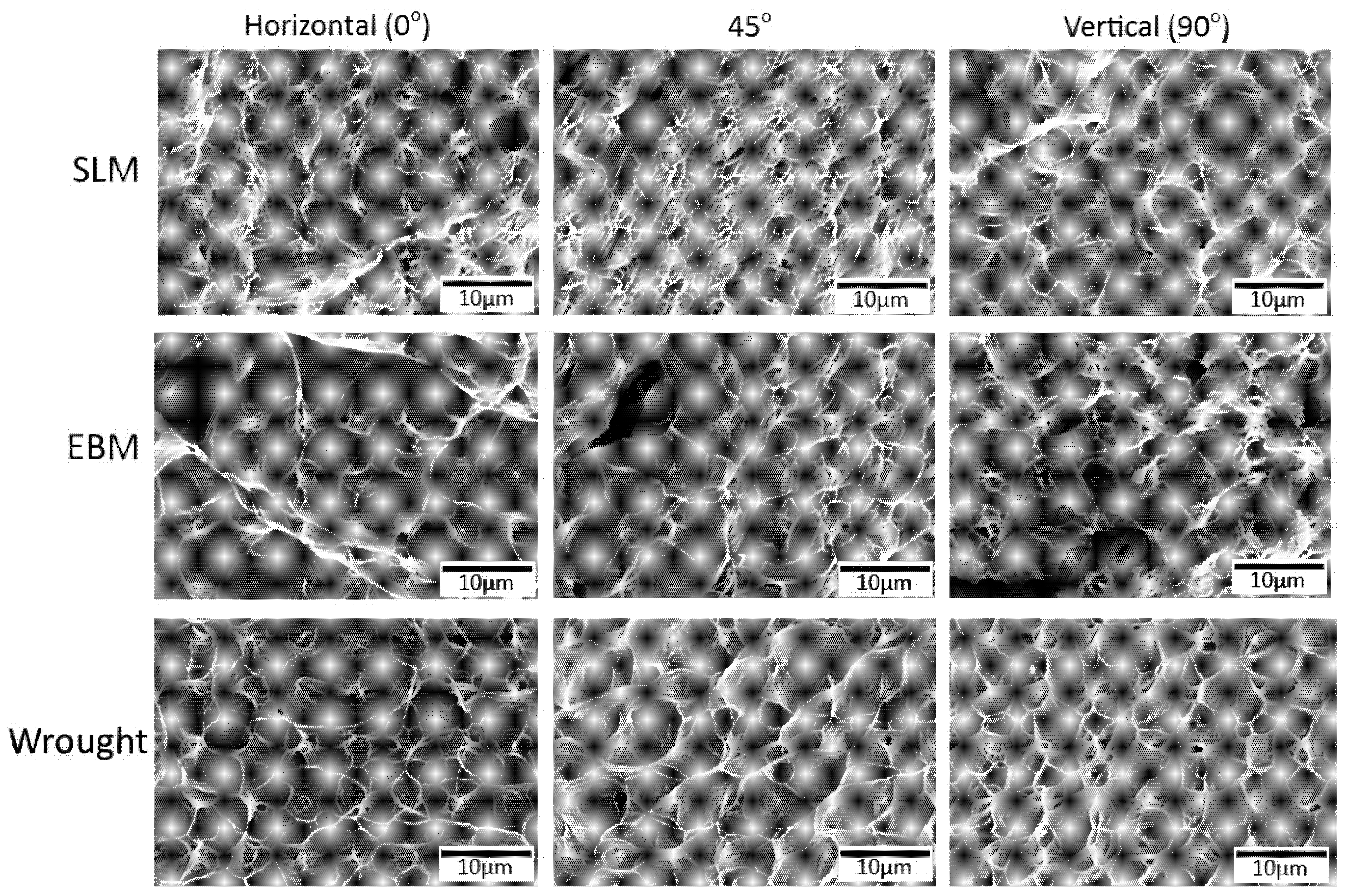
The fracture surfaces of all samples showed dimples (Figure 14) resulting from micro-void coalescence indicating some ductile behavior. Similar features were also reported by others, for example in [25,26].

Figure 14.
SEM micrographs showing high magnification images of fracture surfaces from SLM, EBM and wrought alloy samples. Note the presence of pores on the SLM and EBM samples.
Dimples on the wrought samples were more regular and their distribution was also more uniform. The SLM samples had some small spherical gas pores, while the EBM samples showed some relatively larger irregular (crack-like) pores. From the shape of the pores, it can be assumed that the cause of those pores were different, e.g., gas entrapment around the melt pool on the former [4], and incomplete melting and solidification due to insufficient energy input on the latter [4]. The difference shapes and size of pores in EBM and SLM could be associated with the scanning strategy as well as the size of the powder and /or the parameters used which may produce different energy density. Gong et al. [26] reported the effect of processing parameters (led to different energy density) which caused different size and type of defects. Various types of AM defects have been reported such as balling [4], gas porosity and lack of fusion [42,43]. Shipley et al. further explained that SLM is particularly prone melt pool instability as well as wrong parameters, it may lead to various defects such as balling and porosity (spherical or sharp) being the two main ones [4]. As for the gas pore, it is likely due to gas entrapment in the melt pool [18]. The lack of fusion, particularly those of sharp-tip, may act as local stress concentration where cracks could be initiated which lead to a reduced strength [9,42,43] as well as fatigue properties [9,22,44,45,46,47].
4. Summary
A comparison of Ti6Al4V manufactured by SLM and EBM with wrought alloy has been investigated. Both the SLM and EBM were in the as-printed condition, while the wrought alloy was in the as-received condition. The summary from this investigation are as follows:
- The microstructures of the samples were significantly different with α’ martensite on the SLM, acicular α on EBM and combination of both on the wrought alloy.
- EBM samples had higher surface roughness (Ra) compared with both SLM and wrought alloy. For AM materials, the surface roughness was associated with the size of the particle and the improper melting.
- SLM samples were comparatively harder than wrought alloy and EBM.
- Tensile strength of the wrought alloy was higher in all directions except for 45°, where the SLM samples showed higher strength than both EBM and wrought alloy for the same direction. The ductility of the wrought alloy was consistently higher than both SLM and EBM indicated by clear necking feature on the wrought alloy samples. The variations in mechanical properties is believed to be associated with anisotropy on the samples.
- All the fracture surfaces showed some dimples indicating with wrought samples had more uniform dimples than the AM samples. Defects, i.e., porosity and crack-like defects were present on both SLM and EBM samples.
Author Contributions
Conceptualization T.P., B.T., B.J. and M.F.; methodology, T.P. and B.T.; software O.Y.; formal analysis, T.P., B.T., B.J., M.F.; investigation, T.P., B.T., Y.T. and C.T.; resources, T.P., B.T., J.-C.W., C.-P.J., Y.S. and M.T.; writing—original draft preparation, T.P., B.J., M.F. and W.Z.M.; review and editing, T.P., M.F. and W.Z.M.; project administration, T.P., J.-C.W., C.-P.J., Y.S., M.T. and W.Z.M. All authors have read and agreed to the published version of the manuscript.
Funding
This research received no external funding.
Institutional Review Board Statement
Not applicable.
Informed Consent Statement
Not applicable.
Data Availability Statement
Not applicable.
Acknowledgments
One of the authors (TP) would like to thank the support from the (1) Additive Manufacturing Center for Mass Customization Production (AMC), National Taipei University of Technology, (2) Joining and Welding Research Institute, Osaka University for their continued support, and (3) Loewy Institute for Metal Forming, Lehigh University for the support to complete this article.
Conflicts of Interest
Authors declare no conflict of interest.
References
- Froes, F. Additive manufacturing of titanium components: An update. Met. Powder Rep. 2018, 73, 329–337. [Google Scholar] [CrossRef]
- Sochalski-Kolbus, L.M.; Payzant, E.; Cornwell, P.A.; Watkins, T.; Babu, S.S.; Dehoff, R.R.; Lorenz, M.; Ovchinnikova, O.; Duty, C. Comparison of residual stresses in Inconel 718 simple parts made by electron beam melting and direct laser metal sintering. Met. Mater. Trans. A 2015, 46, 1419–1432. [Google Scholar] [CrossRef]
- Kumar, S. Selective Laser Sintering/Melting. In Comprehensive Materials Processing; Hashmi, S., Ferreira Batalha, G., Yilbas, B., Eds.; Elsevier: Amsterdam, The Netherlands, 2014; Volume 10. [Google Scholar]
- Shipley, H.; McDonnell, D.; Culleton, M.; Coull, R.; Lupoi, R.; O’Donnell, G.; Trimble, D. Optimisation of process parameters to address fundamental challenges during selective laser melting of Ti-6Al-4V: A review. Int. J. Mach. Tools Manuf. 2018, 128, 1–20. [Google Scholar] [CrossRef]
- Lewandowski, J.J.; Seifi, M. Metal additive manufacturing: A review of mechanical properties. Annu. Rev. Mater. Res. 2016, 46, 151–186. [Google Scholar] [CrossRef] [Green Version]
- Debroy, T.; Wei, H.L.; Zuback, J.S.; Mukherjee, T.; Elmer, J.W.; Milewski, J.O.; Beese, A.M.; Wilson-Heid, A.D.; De, A.; Zhang, W. Additive manufacturing of metallic components—Process, structure and properties. Prog. Mater. Sci. 2018, 92, 112–224. [Google Scholar] [CrossRef]
- Herzog, D.; Seyda, V.; Wycisk, E.; Emmelmann, C. Additive manufacturing of metals. Acta Mater. 2016, 117, 371–392. [Google Scholar] [CrossRef]
- Zhang, L.; Liu, Y.; Li, S.; Hao, Y. Additive manufacturing of titanium alloys by electron beam melting: A review. Adv. Eng. Mater. 2018, 20, 1–16. [Google Scholar] [CrossRef]
- Tiferet, E.; Ganor, M.; Zolotaryov, D.; Garkun, A.; Hadjadj, A.; Chonin, M.; Ganor, Y.; Noiman, D.; Halevy, I.; Tevet, O.; et al. Mapping the tray of electron beam melting of Ti-6Al-4V: Properties and microstructure. Materials 2019, 12, 1470. [Google Scholar] [CrossRef] [Green Version]
- Vrancken, B.; Thijs, L.; Kruth, J.-P.; Van Humbeeck, J. Heat treatment of Ti6Al4V produced by Selective Laser Melting: Microstructure and mechanical properties. J. Alloy. Compd. 2012, 541, 177–185. [Google Scholar] [CrossRef] [Green Version]
- Murr, L.; Esquivel, E.; Quinones, S.; Gaytan, S.; Lopez, M.; Martinez, E.; Medina, F.; Hernandez, D.; Martinez, J.; Stafford, S.; et al. Microstructures and mechanical properties of electron beam-rapid manufactured Ti–6Al–4V biomedical prototypes compared to wrought Ti–6Al–4V. Mater. Charact. 2009, 60, 96–105. [Google Scholar] [CrossRef]
- Facchini, L.; Magalini, E.; Robotti, P.; Molinari, A.; Höges, S.; Wissenbach, K. Ductility of a Ti-6Al-4V alloy produced by selective laser melting of prealloyed powders. Rapid Prototyp. J. 2010, 16, 450–459. [Google Scholar] [CrossRef]
- Ren, S.; Chen, Y.; Liu, T.; Qu, X. Effect of build orientation on mechanical properties and microstructure of Ti-6Al-4V manufactured by selective laser melting. Met. Mater. Trans. A 2019, 50, 4388–4409. [Google Scholar] [CrossRef]
- Azarniya, A.; Colera, X.G.; Mirzaali, M.J.; Sovizi, S.; Bartolomeu, F.; Mare, K.S.W.; Wits, W.W.; Yap, C.Y.; Ahn, J.; Miranda, G.; et al. Additive manufacturing of Ti–6Al–4V parts through laser metal deposition (LMD): Process, microstructure, and mechanical properties. J. Alloy. Compd. 2019, 804, 163–191. [Google Scholar] [CrossRef]
- Chern, A.H.; Nandwana, P.; McDaniels, R.; Dehoff, R.R.; Liaw, P.K.; Tryon, R.; Duty, C.E. Build orientation, surface roughness, and scan path influence on the microstructure, mechanical properties, and flexural fatigue behavior of Ti–6Al–4V fabricated by electron beam melting. Mater. Sci. Eng. A 2020, 772, 138740. [Google Scholar] [CrossRef]
- De Formanoir, C.; Brulard, A.; Vivès, S.; Martin, G.; Prima, F.; Michotte, S.; Rivière, E.; Dolimont, A.; Godet, S. A strategy to improve the work-hardening behavior of Ti–6Al–4V parts produced by additive manufacturing. Mater. Res. Lett. 2017, 5, 201–208. [Google Scholar] [CrossRef] [Green Version]
- Karlsson, J.; Snis, A.; Engqvist, H.; Lausmaa, J. Characterization and comparison of materials produced by Electron Beam Melting (EBM) of two different Ti–6Al–4V powder fractions. J. Mater. Process. Technol. 2013, 213, 2109–2118. [Google Scholar] [CrossRef]
- Galarraga, H.; Lados, D.A.; Dehoff, R.R.; Kirka, M.M.; Nandwana, P. Effects of the microstructure and porosity on properties of Ti-6Al-4V ELI alloy fabricated by electron beam melting (EBM). Addit. Manuf. 2016, 10, 47–57. [Google Scholar] [CrossRef] [Green Version]
- Edwards, P.; Ramulu, M. Fatigue performance evaluation of selective laser melted Ti–6Al–4V. Mater. Sci. Eng. A 2014, 598, 327–337. [Google Scholar] [CrossRef]
- Thijs, L.; Verhaeghe, F.; Craeghs, T.; Van Humbeeck, J.; Kruth, J.-P. A study of the microstructural evolution during selective laser melting of Ti–6Al–4V. Acta Mater. 2010, 58, 3303–3312. [Google Scholar] [CrossRef]
- Vilaro, T.; Colin, C.; Bartout, J.-D. As-fabricated and heat-treated microstructures of the Ti-6Al-4V alloy processed by selective laser melting. Met. Mater. Trans. A 2011, 42, 3190–3199. [Google Scholar] [CrossRef]
- Chastand, V.; Quaegebeur, P.; Maia, W.; Charkaluk, E. Comparative study of fatigue properties of Ti-6Al-4V specimens built by electron beam melting (EBM) and selective laser melting (SLM). Mater. Charact. 2018, 143, 76–81. [Google Scholar] [CrossRef]
- Murr, L.E.; Gaytan, S.M.; Ramirez, D.A.; Martinez, E.; Hernandez, J.; Amato, K.N.; Shindo, P.W.; Medina, F.R.; Wicker, R.B. Metal fabrication by additive manufacturing using laser and electron beam melting technologies. J. Mater. Sci. Technol. 2012, 28, 1–14. [Google Scholar] [CrossRef]
- Rafi, H.K.; Karthik, N.V.; Gong, H.; Starr, T.L.; Stucker, B.E. Microstructures and mechanical properties of Ti6Al4V parts fabricated by selective laser melting and electron beam melting. J. Mater. Eng. Perform. 2013, 22, 3872–3883. [Google Scholar] [CrossRef]
- Gokuldoss, P.K.; Kolla, S.; Eckert, J. Additive manufacturing processes: Selective laser melting, electron beam melting and binder jetting—Selection guidelines. Materials 2017, 10, 672. [Google Scholar] [CrossRef] [PubMed] [Green Version]
- Gong, H.; Rafi, K.; Starr, T.; Stucker, B. The effects of processing parameters on defect regularity in Ti-6Al-4V parts fabricated by selective laser melting and electron beam melting. In Proceedings of the 24th Annual International Solid Freeform Fabrication Symposium—An Additive Manufacturing Conference, Austin, TX, USA, 12–14 August 2013. [Google Scholar]
- Fousová, M.; Vojtěch, D.; Doubrava, K.; Daniel, M.; Lin, C.-F. Influence of inherent surface and internal defects on mechanical properties of additively manufactured Ti6Al4V alloy: Comparison between selective laser melting and electron beam melting. Materials 2018, 11, 537. [Google Scholar] [CrossRef] [PubMed] [Green Version]
- Zhao, X.; Li, S.; Zhang, M.; Liu, Y.; Sercombe, T.B.; Wang, S.; Hao, Y.; Yang, R.; Murr, L. Comparison of the microstructures and mechanical properties of Ti–6Al–4V fabricated by selective laser melting and electron beam melting. Mater. Des. 2016, 95, 21–31. [Google Scholar] [CrossRef]
- Ganor, Y.I.; Tiferet, E.; Vogel, S.C.; Brown, D.W.; Chonin, M.; Pesach, A.; Hajaj, A.; Garkun, A.; Samuha, S.; Shneck, R.Z.; et al. Tailoring microstructure and mechanical properties of additively-manufactured Ti6Al4V Using post processing. Materials 2021, 14, 658. [Google Scholar] [CrossRef]
- Yeheskel, O.; Dariel, M. The effect of processing on the elastic moduli of porous γ-TiAl. Mater. Sci. Eng. A 2003, 354, 344–350. [Google Scholar] [CrossRef]
- Qiu, C.; Adkins, N.J.; Attallah, M.M. Microstructure and tensile properties of selectively laser-melted and of HIPed laser-melted Ti–6Al–4V. Mater. Sci. Eng. A 2013, 578, 230–239. [Google Scholar] [CrossRef]
- Xu, W.; Brandt, M.; Sun, S.; Elambasseril, J.; Liu, Q.; Latham, K.; Xia, K.; Qian, M. Additive manufacturing of strong and ductile Ti–6Al–4V by selective laser melting via in situ martensite decomposition. Acta Mater. 2015, 85, 74–84. [Google Scholar] [CrossRef]
- Hrabe, N.; Quinn, T. Effects of processing on microstructure and mechanical properties of a titanium alloy (Ti–6Al–4V) fabricated using electron beam melting (EBM), Part 2: Energy input, orientation, and location. Mater. Sci. Eng. A 2013, 573, 271–277. [Google Scholar] [CrossRef]
- Kahnert, M.; Lutzmann, S.; Zaeh, M.F. Layer formations in electron beam sintering. In Solid Freeform Fabrication Symposium; University of Texas at Austin: Austin, TX, USA, 2007; pp. 88–99. [Google Scholar]
- Song, B.; Dong, S.; Zhang, B.; Liao, H.; Coddet, C. Effects of processing parameters on microstructure and mechanical property of selective laser melted Ti6Al4V. Mater. Des. 2012, 35, 120–125. [Google Scholar] [CrossRef]
- Ventura, A.P.; Wade, C.A.; Pawlikowski, G.; Bayes, M.; Watanabe, M.; Misiolek, W.Z. Mechanical properties and microstructural characterization of Cu-4.3 Pct Sn fabricated by selective laser melting. Met. Mater. Trans. A 2016, 48, 178–187. [Google Scholar] [CrossRef]
- Frazier, W.E. Metal Additive Manufacturing: A Review. J. Mater. Eng. Perform. 2014, 23, 1917–1928. [Google Scholar] [CrossRef]
- Spierings, A.; Herres, N.; Levy, G.J. Influence of the particle size distribution on surface quality and mechanical properties in AM steel parts. Rapid Prototyp. J. 2011, 17, 195–202. [Google Scholar] [CrossRef] [Green Version]
- Hutchinson, B. Critical Assessment 16: Anisotropy in metals. Mater. Sci. Technol. 2015, 31, 1393–1401. [Google Scholar] [CrossRef] [Green Version]
- He, B.; Wu, W.; Zhang, L.; Lu, L.; Yang, Q.; Long, Q.; Chang, K. Microstructural characteristic and mechanical property of Ti6Al4V alloy fabricated by selective laser melting. Vacuum 2018, 150, 79–83. [Google Scholar] [CrossRef]
- Agius, D.J.; Kourousis, K.I.; Wallbrink, C. A review of the As-Built SLM Ti-6Al-4V mechanical properties towards achieving fatigue resistant designs. Metals 2018, 8, 75. [Google Scholar] [CrossRef] [Green Version]
- Li, P.-H.; Guo, W.-G.; Huang, W.-D.; Su, Y.; Lin, X.; Yuan, K.-B. Thermomechanical response of 3D laser-deposited Ti–6Al–4V alloy over a wide range of strain rates and temperatures. Mater. Sci. Eng. A 2015, 647, 34–42. [Google Scholar] [CrossRef]
- Liu, S.; Shin, Y.C. Additive manufacturing of Ti6Al4V alloy: A review. Mater. Des. 2019, 164, 107552. [Google Scholar] [CrossRef]
- Leuders, S.; Thöne, M.; Riemer, A.; Niendorf, T.; Tröster, T.; Richard, H.; Maier, H. On the mechanical behaviour of titanium alloy TiAl6V4 manufactured by selective laser melting: Fatigue resistance and crack growth performance. Int. J. Fatigue 2013, 48, 300–307. [Google Scholar] [CrossRef]
- Liu, Q.C.; Elambasseril, J.; Sun, S.J.; Leary, M.; Brandt, M.; Sharp, P.K. The effect of manufacturing defects on the fatigue behaviour of Ti-6Al-4V specimens fabricated using selective laser melting. Adv. Mater. Res. 2014, 891–892, 1519–1524. [Google Scholar] [CrossRef]
- Gong, H.; Rafi, K.; Gu, H.; Ram, G.J.; Starr, T.; Stucker, B. Influence of defects on mechanical properties of Ti–6Al–4V components produced by selective laser melting and electron beam melting. Mater. Des. 2015, 86, 545–554. [Google Scholar] [CrossRef]
- Wycisk, E.; Solbach, A.; Siddique, S.; Herzog, D.; Walther, F.; Emmelmann, C. Effects of defects in laser additive manufactured Ti-6Al-4V on fatigue properties. Phys. Procedia 2014, 56, 371–378. [Google Scholar] [CrossRef] [Green Version]

Publisher’s Note: MDPI stays neutral with regard to jurisdictional claims in published maps and institutional affiliations. |
© 2021 by the authors. Licensee MDPI, Basel, Switzerland. This article is an open access article distributed under the terms and conditions of the Creative Commons Attribution (CC BY) license (https://creativecommons.org/licenses/by/4.0/).