
Cartilage Tissue Engineering by Extrusion Bioprinting: Process Analysis, Risk Evaluation, and Mitigation Strategies


Abstract
:
1. Introduction
2. Materials and Methods
2.1. Choice of the Process
- (i)
- Process diffusion in terms of literature data, agency reports, lab presence, the potential for translation into clinical practice, or already known clinical applications.
- (ii)
- Process complexity in terms of time length, number of steps, involved operators, and complex technologies.
- (iii)
- Severity of possible harmful events/reagents.
- (iv)
- Recurrent issues in the lab related to the process.
2.2. Team Composition
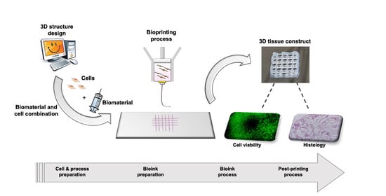
2.3. Process Mapping and Product Quality Evaluation
2.3.1. Process Mapping
2.3.2. Product Quality Evaluation
2.4. Risk Analysis
2.4.1. FMEA/FMECA
2.4.2. Improvement Actions and Monitoring
3. Results
3.1. Choice of the Process
- (i)
- Extrusion bioprinting—which uses viscous gels/pastes—does not need a melting step, thus allowing cell surviving and embedding. For this reason, most commercial bioprinters are based on this technology [20]. Moreover, it has proved to be far more reliable for tissue engineering applications because of its ability to mimic the structural and functional complexity of cartilage tissue. We selected a collagen type I-based hydrogel as bioink, which has been demonstrated to be suitable for cartilage tissue engineering applications by improving cell viability, attachment, proliferation, and homing [21]. Moreover, due to the low immunogenicity, it has been already utilized in clinical investigations [22,23]. Regarding cell component, MSCs were selected thanks to their unique properties: (a) the ability to self-renew and to differentiate toward several phenotypes including the chondrogenic one; (b) the immune-privileged status; and (c) the ability to release a plethora of active factors capable of modulating the local microenvironment (paracrine activity).
- (ii)
- (iii)
- Due to the presence of embedded live cells, generally, bioprinting processes do not involve harmful/toxic reagents. Using thermosensitive materials such as collagen could enable to get rid of chemical or UV activated crosslinking processes affecting cell survival [27]. We considered these risks in the FMEA/FMECA because these processes may be adopted in some applications, as reported in the discussion paragraph. It is also to be considered that, in certain cases, collagen bioink is stored in a solution of acetic acid and neutralized immediately before their combination with cells [27].
- (iv)
- The death of encapsulated cells due to the high level of shear stresses generated along the nozzle may represent a recurrent issue. This risk is strongly reduced by (a) the use of low viscosity natural polymers, such as collagen, that can undergo quick gelation or crosslinking process post-deposition; and (b) by the adoption of ad hoc solutions for the process (e.g., increased needle diameter or use of conical needles) [13].
3.2. Team Composition and Timetable
3.3. Process Mapping and Product Quality Evaluation
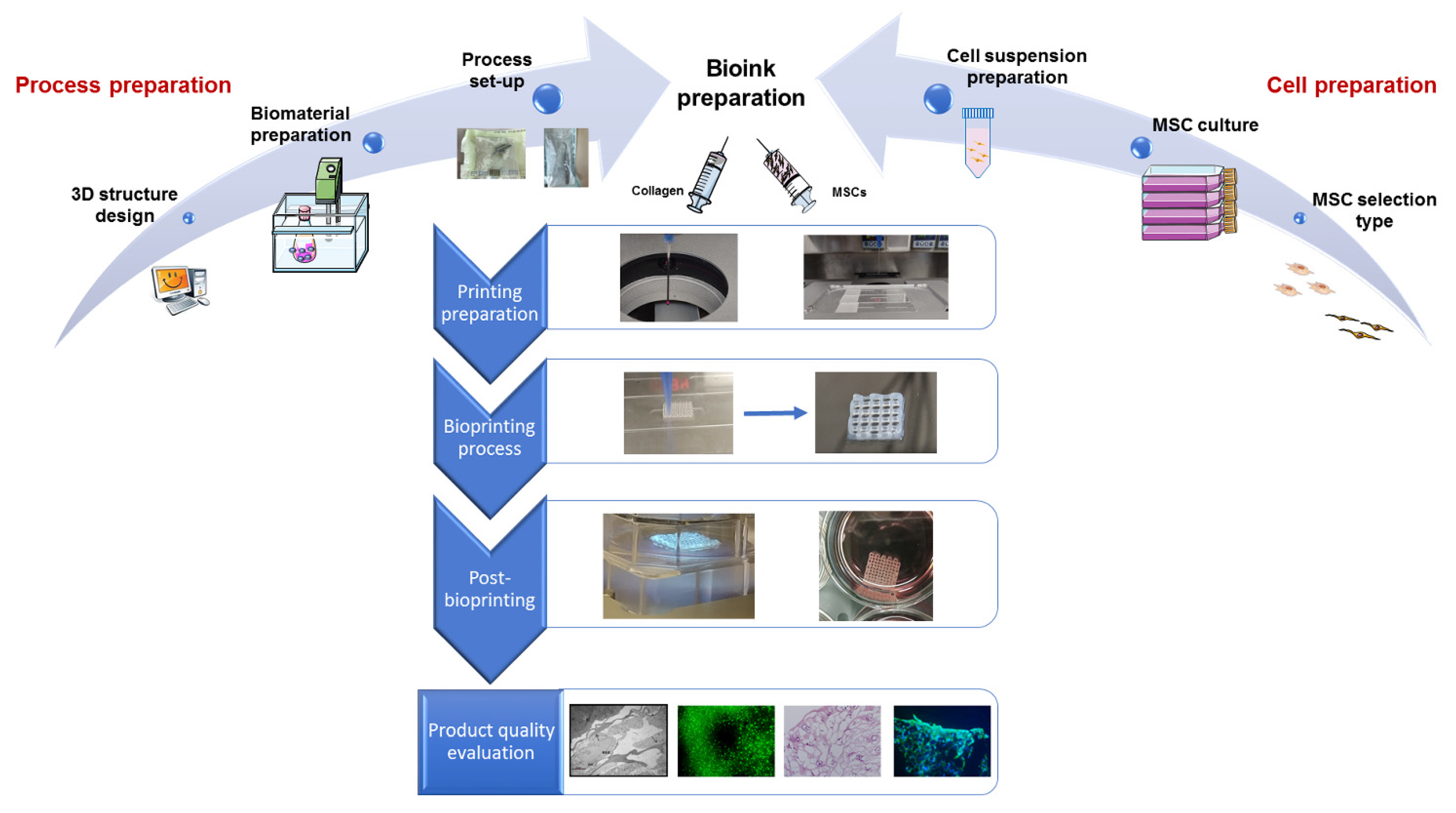
3.3.1. Process Mapping
- (i)
- 3D structure design (4 activities);
- (ii)
- Biomaterial preparation (6 activities);
- (iii)
- Process set-up (3 activities).
- (i)
- MSC selection type (2 activities);
- (ii)
- MSC culture (3 activities);
- (iii)
- Cell suspension preparation (3 activities).
- (i)
- Bioink preparation (4 activities);
- (ii)
- Printing preparation (3 activities);
- (iii)
- Bioprinting process (4 activities).
- (i)
- Cross-linking;
- (ii)
- Incubation at 37 °C, 95% relative humidity, 5% CO2.
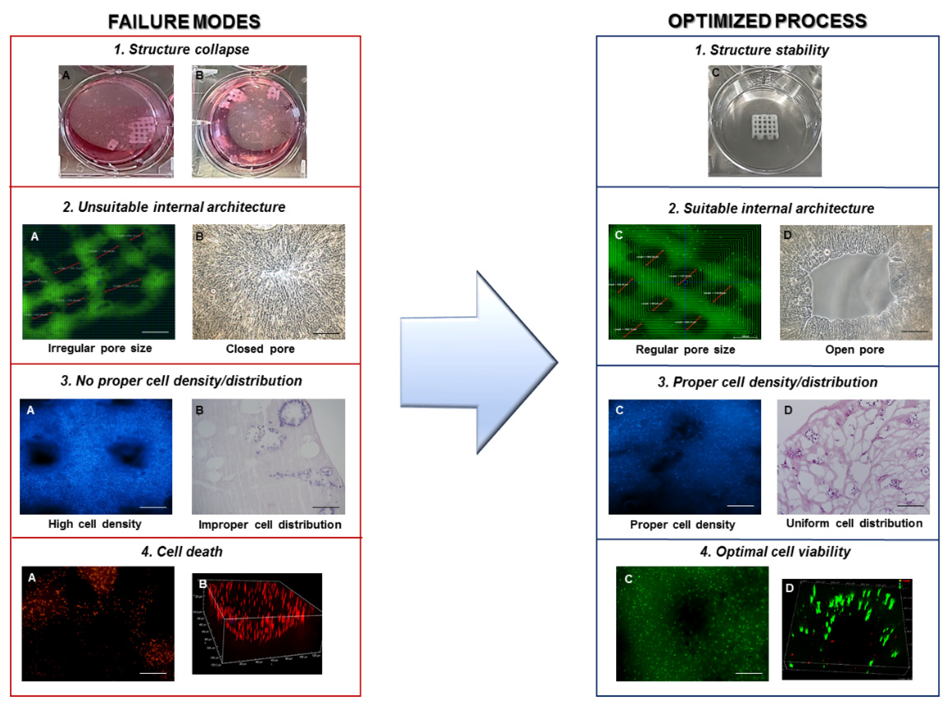
3.3.2. Product Quality Evaluation
- (i)
- Printing fidelity, defined as a construct with a well-defined shape and architecture, by matching the fabricated object morphological features to the designed ones. The design should be adapted to provide the constructs with the required transport properties to guarantee nutrient supply, mechanical properties to mimic the native tissue, as well as favoring cell well-being and cartilage ECM production;
- (ii)
- Cell-laden construct shape retention (microscopic, pore, and filament size) and stability over time, both dependent on the selected material properties and the implemented crosslinking mechanisms. Failure in meeting this condition will inevitably result in sample loss;
- (iii)
- Cell viability, affected by shear stresses, environment conditions, and crosslinking mechanisms, which may cause phenotypical and functional changes of cells or death;
- (iv)
- Absence of microbiological contamination causing cell death and microbial growth;
- (v)
- Interaction between cells and scaffold evaluated through specific morphological assessment including scanning electron microscopy (SEM) and histology;
- (vi)
- Cell ability to differentiate toward the cartilage phenotype, dependent on the clinical need, choice of the cell source, cell types, and culture conditions, as well as morphology of the fabricated constructs as specified in point (i).
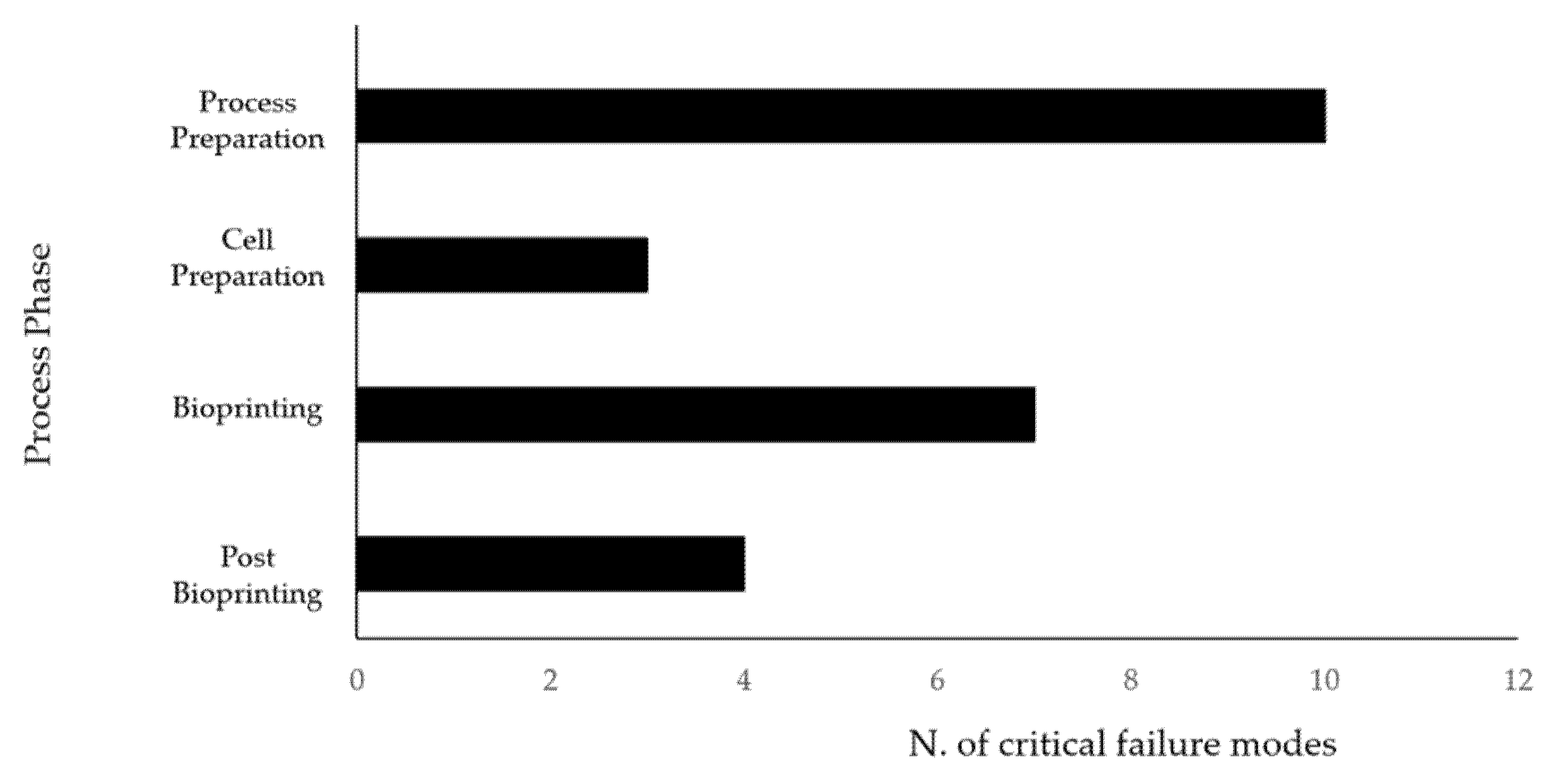
3.4. Risk Analysis
4. Discussion
5. Conclusions
Author Contributions
Funding
Institutional Review Board Statement
Informed Consent Statement
Data Availability Statement
Acknowledgments
Conflicts of Interest
References
- Roseti, L.; Cavallo, C.; Desando, G.; Parisi, V.; Petretta, M.; Bartolotti, I.; Grigolo, B. Three-dimensional bioprinting of cartilage by the use of stem cells: A strategy to improve regeneration. Materials 2018, 11, 1749. [Google Scholar] [CrossRef] [Green Version]
- Liu, Y.; Zhou, G.; Cao, Y. Recent Progress in Cartilage Tissue Engineering—Our Experience and Future Directions. Engineering 2017, 3, 28–35. [Google Scholar] [CrossRef]
- Gomoll, A.H.; Minas, T. The quality of healing: Articular cartilage. Wound Repair Regen. 2014, 22, 30–38. [Google Scholar] [CrossRef] [PubMed]
- Borrelli, J.J.; Olson, S.A.; Godbout, C.; Schemitsch, E.H.; Stannard, J.P.; Giannoudis, P.V. Understanding Articular Cartilage Injury and Potential Treatments. J. Orthop. Trauma 2019, 33, S6–S12. [Google Scholar] [CrossRef] [PubMed]
- Lewis, P.B.; McCarty, L.P.; Kang, R.W.; Cole, B.J. Basic Science and Treatment Options for Articular Cartilage Injuries. J. Orthop. Sports Phys. Ther. 2006, 36, 717–727. [Google Scholar] [CrossRef] [PubMed] [Green Version]
- Gracitelli, G.C.; Moraes, V.Y.; Franciozi, C.E.S.; Luzo, M.V.; Belloti, J.C. Surgical interventions (microfracture, drilling, mosaicplasty, and allograft transplantation) for treating isolated cartilage defects of the knee in adults. Cochrane Database Syst. Rev. 2016. [Google Scholar] [CrossRef]
- Myers, K.R.; Sgaglione, N.A.; Grande, D.A. Trends in biological joint resurfacing. Bone Jt. Res. 2013, 2, 193–199. [Google Scholar] [CrossRef]
- Vinatier, C.; Guicheux, J. Cartilage tissue engineering: From biomaterials and stem cells to osteoarthritis treatments. Ann. Phys. Rehabil. Med. 2016, 59, 139–144. [Google Scholar] [CrossRef]
- Armiento, A.R.; Stoddart, M.J.; Alini, M.; Eglin, D. Biomaterials for articular cartilage tissue engineering: Learning from biology. Acta Biomater. 2018, 65, 1–20. [Google Scholar] [CrossRef]
- Campos, Y.; Almirall, A.; Fuentes, G.; Bloem, H.L.; Kaijzel, E.L.; Cruz, L.J. Tissue Engineering: An Alternative to Repair Cartilage. Tissue Eng. Part B Rev. 2019, 25, 357–373. [Google Scholar] [CrossRef]
- Chan, B.P.; Leong, K.W. Scaffolding in tissue engineering: General approaches and tissue-specific considerations. Eur. Spine J. 2008, 17. [Google Scholar] [CrossRef] [PubMed] [Green Version]
- Semba, J.A.; Mieloch, A.A.; Rybka, J.D. Introduction to the state-of-the-art 3D bioprinting methods, design, and applications in orthopedics. Bioprinting 2020, 18, e00070. [Google Scholar] [CrossRef]
- Daly, A.C.; Freeman, F.E.; Gonzalez-Fernandez, T.; Critchley, S.E.; Nulty, J.; Kelly, D.J. 3D Bioprinting for Cartilage and Osteochondral Tissue Engineering. Adv. Healthc. Mater. 2017, 6, 1–20. [Google Scholar] [CrossRef] [PubMed]
- Abdollahiyan, P.; Oroojalian, F.; Mokhtarzadeh, A.; de la Guardia, M. Hydrogel-Based 3D Bioprinting for Bone and Cartilage Tissue Engineering. Biotechnol. J. 2020, 15, 2000095. [Google Scholar] [CrossRef] [PubMed]
- Loai, S.; Kingston, B.R.; Wang, Z.; Philpott, D.N.; Tao, M.; Cheng, H.-L.M. Clinical Perspectives on 3D Bioprinting Paradigms for Regenerative Medicine. Regen. Med. Front. 2019, 1, e190004. [Google Scholar] [CrossRef]
- Onofrio, R.; Piccagli, F.; Segato, F. Failure Mode, Effects and Criticality Analysis (FMECA) for Medical Devices: Does Standardization Foster Improvements in the Practice? Procedia Manuf. 2015, 3, 43–50. [Google Scholar] [CrossRef] [Green Version]
- Chiozza, M.L.; Ponzetti, C. FMEA: A model for reducing medical errors. Clin. Chim. Acta 2009, 404, 75–78. [Google Scholar] [CrossRef] [PubMed]
- Roseti, L.; Serra, M.; Bassi, A.; Venezian, T.; Maso, A.; Fornasari, P.M.; Di Denia, P.; Munno, C.; Storni, E.; Grigolo, B. Failure Mode and Effects Analysis to Reduce Risks of Errors in the Good Manufacturing Practice Production of Engineered Cartilage for Autologous Chondrocyte Implantation. Curr. Pharm. Anal. 2016, 12, 43–54. [Google Scholar] [CrossRef]
- Mascia, A.; Cirafici, A.M.; Bongiovanni, A.; Colotti, G.; Lacerra, G.; Di Carlo, M.; Digilio, F.A.; Liguori, G.L.; Lanati, A.; Kisslinger, A. A failure mode and effect analysis (FMEA)-based approach for risk assessment of scientific processes in non-regulated research laboratories. Accredit. Qual. Assur. 2020, 25, 311–321. [Google Scholar] [CrossRef]
- Petretta, M.; Desando, G.; Grigolo, B.; Roseti, L. 3D printing of musculoskeletal tissues: Impact on safety and health at work. J. Toxicol. Environ. Health Part A Curr. Issues 2019. [Google Scholar] [CrossRef]
- Antoine, E.E.; Vlachos, P.P.; Rylander, M.N. Review of collagen I hydrogels for bioengineered tissue microenvironments: Characterization of mechanics, structure, and transport. Tissue Eng. Part B Rev. 2014, 20, 683–696. [Google Scholar] [CrossRef] [PubMed] [Green Version]
- Osidak, E.O.; Kozhukhov, V.I.; Osidak, M.S.; Domogatsky, S.P. Collagen as Bioink for Bioprinting: A Comprehensive Review. Int. J. Bioprinting 2020, 6, 270. [Google Scholar] [CrossRef]
- Lynn, A.K.; Yannas, I.V.; Bonfield, W. Antigenicity and immunogenicity of collagen. J. Biomed. Mater. Res. Part B Appl. Biomater. 2004, 71B, 343–354. [Google Scholar] [CrossRef] [PubMed]
- Irvine, S.A.; Venkatraman, S.S. Bioprinting and Differentiation of Stem Cells. Molecules 2016, 21, 1188. [Google Scholar] [CrossRef]
- Tsumaki, N.; Okada, M.; Yamashita, A. iPS cell technologies and cartilage regeneration. Bone 2015, 70, 48–54. [Google Scholar] [CrossRef] [PubMed]
- Roseti, L.; Parisi, V.; Petretta, M.; Cavallo, C.; Desando, G.; Bartolotti, I.; Grigolo, B. Scaffolds for Bone Tissue Engineering: State of the art and new perspectives. Mater. Sci. Eng. C 2017. [Google Scholar] [CrossRef]
- Chan, W.W.; Yeo, D.C.L.; Tan, V.; Singh, S.; Choudhury, D.; Naing, M.W. Additive Biomanufacturing with Collagen Inks. Bioengineering 2020, 7, 66. [Google Scholar] [CrossRef] [PubMed]
- van Leeuwen, J.F.; Nauta, M.J.; de Kaste, D.; Odekerken-Rombouts, Y.M.C.F.; Oldenhof, M.T.; Vredenbregt, M.J.; Barends, D.M. Risk analysis by FMEA as an element of analytical validation. J. Pharm. Biomed. Anal. 2009, 50, 1085–1087. [Google Scholar] [CrossRef]
- Zimmermann, H.F.; Hentschel, N. Proposal on How To Conduct a Biopharmaceutical Process Failure Mode and Effect Analysis (FMEA) as a Risk Assessment Tool. PDA J. Pharm. Sci. Technol. 2011, 65, 506–512. [Google Scholar] [CrossRef]
- Lee, H.; Lee, H.; Baik, J.; Kim, H.; Kim, R. Failure mode and effects analysis drastically reduced potential risks in clinical trial conduct. Drug Des. Devel. Ther. 2017, 11, 3035–3043. [Google Scholar] [CrossRef] [PubMed] [Green Version]
- Derr, K.; Zou, J.; Luo, K.; Song, M.J.; Sittampalam, G.S.; Zhou, C.; Michael, S.; Ferrer, M.; Derr, P. Fully Three-Dimensional Bioprinted Skin Equivalent Constructs with Validated Morphology and Barrier Function. Tissue Eng. Part C Methods 2019, 25, 334–343. [Google Scholar] [CrossRef]
- Sanz-Fraile, H.; Amoros, S.; Mendizabal, I.; Galvez-Monton, C.; Prat-Vidal, C.; Bayes-Genis, A.; Navajas, D.; Farre, R.; Otero, J. Silk-Reinforced Collagen Hydrogels with Raised Multiscale Stiffness for Mesenchymal Cells 3D Culture. Tissue Eng. Part A 2020, 26, 358–370. [Google Scholar] [CrossRef]
- Kim, W.; Kim, G. Collagen/bioceramic-based composite bioink to fabricate a porous 3D {hASCs}-laden structure for bone tissue regeneration. Biofabrication 2019, 12, 15007. [Google Scholar] [CrossRef] [PubMed]
- Marques, C.F.; Diogo, G.S.; Pina, S.; Oliveira, J.M.; Silva, T.H.; Reis, R.L. Collagen-based bioinks for hard tissue engineering applications: A comprehensive review. J. Mater. Sci. Mater. Med. 2019, 30, 32. [Google Scholar] [CrossRef] [PubMed]
- de Windt, T.S.; Vonk, L.A.; Slaper-Cortenbach, I.C.M.; van den Broek, M.P.H.; Nizak, R.; van Rijen, M.H.P.; de Weger, R.A.; Dhert, W.J.A.; Saris, D.B.F. Allogeneic Mesenchymal Stem Cells Stimulate Cartilage Regeneration and Are Safe for Single-Stage Cartilage Repair in Humans upon Mixture with Recycled Autologous Chondrons. Stem Cells 2017, 35, 256–264. [Google Scholar] [CrossRef]
- Filardo, G.; Petretta, M.; Cavallo, C.; Roseti, L.; Durante, S.; Albisinni, U.; Grigolo, B. Patient-specific meniscus prototype based on 3D bioprinting of human cell-laden scaffold. Bone Jt. Res. 2019. [Google Scholar] [CrossRef]
- Yang, K.; Sun, J.; Guo, Z.; Yang, J.; Wei, D.; Tan, Y.; Guo, L.; Luo, H.; Fan, H.; Zhang, X. Methacrylamide-modified collagen hydrogel with improved anti-actin-mediated matrix contraction behavior. J. Mater. Chem. B 2018, 6, 7543–7555. [Google Scholar] [CrossRef]
- Lee, J.; Yeo, M.; Kim, W.; Koo, Y.; Kim, G.H. Development of a tannic acid cross-linking process for obtaining 3D porous cell-laden collagen structure. Int. J. Biol. Macromol. 2018, 110, 497–503. [Google Scholar] [CrossRef] [PubMed]


| Value | Definition | Interpretation |
|---|---|---|
| 1–4 | Impossible/infrequent | It is virtually impossible or rare to occur |
| 5–6 | Occasional/moderate | It occurs a few times |
| 7–8 | Frequent | It often occurs |
| 9–10 | Very frequent/certain | It occurs several times or will certainly occur within a short time |
| Value | Definition | Interpretation |
|---|---|---|
| 1–4 | Low | Technical problems during activity, without implications on product quality |
| 5–6 | Moderate | Minor problems slightly lowering the product quality |
| 7–8 | High | Major problems affecting product quality |
| 9–10 | Dangerous | No product |
| Value | Definition | Interpretation |
|---|---|---|
| 1–4 | Certain/ very high | Errors are usually intercepted before affecting process |
| 5–6 | Medium/high | Errors are trapped unless operator inattention or specific measures are in place to detect potential problems |
| 7–8 | Low | Issues are occasionally detected during the activities |
| 9–10 | Almost zero | Only an external action or intervention other than the routine practice may highlight the error or there is no chance to detect the problem |
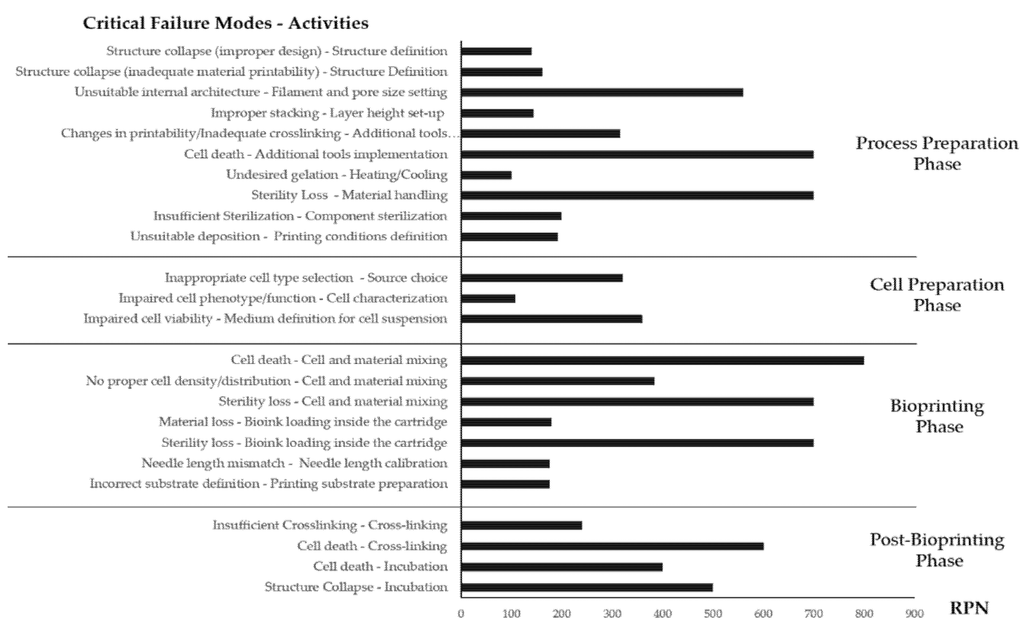
| Step | Activity | Failure Mode | Potential Cause | Possible Consequences | O | S | D | RPN | Mitigation Actions |
|---|---|---|---|---|---|---|---|---|---|
| 3D structuredesign | Structure definition | Collapse | Improper design for fiber deposition (complex structures, overhanging segments) | Failure to replicate the desired shape Structure loss Unsuitable bioprinting results | 4 | 7 | 5 | 140 | Correct orientation of the shape Generate software 3D preview of the designed object |
| Structure definition | Collapse | Inadequate material Printability | Failure to replicate the desired shape Structure loss Unsuitable bioprinting results | 6 | 9 | 3 | 162 | Use of support materials Adapt material formulation to improve rheological properties Perform acellular material deposition tests to adapt process parameters | |
| Filament and pore size setting | Unsuitable internal architecture | A mismatch between the designed filament and fabricated one (use of the different needle, unsuitable material flow) Improper structure definition (pore size, fiber diameter, deposition pattern) | Unsuitable nutrient supply/cell death (closed porosity) Inadequate mechanical properties/structure integrity loss (excess porosity) | 6 | 8 | 2 | 96 | Generate software 3D preview of the designed object. Double-check design parameters about selected consumables before process launch | |
| 3D structure design | Filament and pore size setting | Unsuitable internal architecture | Improper structure definition (pore size, fiber diameter, deposition pattern) | Failure to mimic properties of native tissues to induce cell differentiation and ECM production | 7 | 8 | 10 | 560 | Pilot studies to test different 3D architectures for selecting the best design for cell growth and cartilage tissue production |
| Layer height set-up | Improper stacking | Layer fusion (low layer height) Missing deposition (excessive layer height) | Structure loss Material accumulation on needle tip without structure formation | 9 | 8 | 2 | 144 | Optimization of printing process parameters using acellular material to establish adequate layer height for optimal stacking | |
| Additional tools (heat, UV) implementation | Changes in printability Inadequate crosslinking | Cartridge and/or needle tip temperatures unsuitable for ink flow Platform temperature unsuitable for material crosslinking/gelation Improper dosage of UV irradiation | Improper gelation (Needle clogging, excess deposition) structure collapse/shape loss | 7 | 9 | 5 | 315 | Double-check additional tools settings before process launch Perform preliminary dispensing and crosslinking tests on acellular material Wait additional time, once temperature setpoints are reached, to guarantee thermal equilibrium conditions | |
| 3D structure design | Additional tools (heat, UV) implementation | Cell death | Cartridge temperature inadequate for cell survival Improper dosage of UV irradiation | No biological response Experimental failure | 7 | 10 | 10 | 700 | Evaluate through scientific literature threshold values of cell exposure to crosslinking agent Wait for additional time once temperature setpoints are reached, to guarantee thermal equilibrium conditions |
| Biomaterial preparation | Dissolving in liquid medium | Incomplete dissolution | Use of ineffective solvent Solution Saturation Improper dissolution procedure | Sedimentation Decreased bioactive concentration Unsuitable rheological/printability properties | 4 | 6 | 2 | 48 | Obtain solubility data (max concentration/solvent compatibility) from scientific literature or material supplier Follow operative instructions for material dissolution provided by the supplier |
| Stirring | Inhomogeneous distribution | Insufficient time Incorrect procedure (temperature, material addition ratio, speed) | Formation of aggregates/lumps Decreased bioactive concentration Unsuitable rheological/printability properties | 4 | 6 | 2 | 48 | Optimize material dissolution parameters preliminarily with small material amounts Follow the defined operative instructions | |
| Biomaterial preparation | Mixing | Unsuitable rheology | Incorrect mixing ratio | Unsuitable rheological/printability properties | 3 | 6 | 5 | 90 | Request optimized mixing ratio to the supplier or identify a suitable starting ratio from scientific literature Perform preliminary tests on material dispensing and deposition to evaluate formulation printability |
| Heating/cooling | Undesired gelation | Material kept above/below required temperature for a prolonged time during the preparation phase | Manipulation issues Needle clogging | 5 | 5 | 4 | 100 | Follow operative instructions provided by the manufacturer Check reaching and keeping of the temperature setpoints throughout the process | |
| Centrifuging/ vortexing | Material inhomogeneity | Incorrect settings (time, speed) Unforeseen material Properties | Unsuitable deposition/needle clogging (air bubbles presence) Phase separation (sedimentation due to excess centrifuging) Undesired gelation | 4 | 6 | 2 | 48 | Check for available optimized parameters set from scientific literature or distributors Visually inspect centrifuged–vortexed solutions for signs of sedimentation/gelation | |
| Biomaterial preparation | Material handling | Sterility loss | Improper handling procedure Non-sterile environment | Culture contamination Experiment failure Material waste | 7 | 10 | 10 | 700 | Follow sterile work procedures Visual inspection to identify sterility losses of required consumables (e.g., autoclave bags integrity) Regular maintenance/calibration of biological safety hoods |
| Process set-up | Disposable selection and preparation | Disposable unavailability | Out of stock Mismatch between selected disposables and design Disposable loss due to issues during the process | Incorrect process parameters (needle mismatch) Process interruption (lack of required disposables) | 3 | 5 | 5 | 90 | Keep an updated stock register Proactively reorder disposables close to consumption/expiry Plan 2 backup disposable sets for each experiment |
| Sterilization of the required components—printing environment | Insufficient sterilization | Unsuitable sterilization method Sterilization Procedure failure | Culture contamination Experiment failure Material waste | 2 | 10 | 10 | 200 | Identify compatible sterilization procedures Follow operative instructions for sterilization procedures. Visual inspection to identify unforeseen failures (e.g., autoclave bags integrity) | |
| Process set-up | Printing conditions definition | Unsuitable deposition | Improper process parameters | Shape loss Variation in the internal architecture Structure collapse Process interruption (needle clogging) | 6 | 8 | 4 | 192 | Acellular optimization of printing process First tests with low amounts of cell-laden material Check that desired process conditions have been reached and stable before running the process |
| Step | Activity | Failure Mode | Potential Cause | Possible Consequences | O | S | D | RPN | Mitigation Actions |
|---|---|---|---|---|---|---|---|---|---|
| MSC selection type | Clinical need evaluation/Source choice | Inappropriate cell type selection | Inadequate cell response | Impaired chondroprotective cell potential | 5 | 8 | 8 | 320 | Definition of new selection criteria |
| MSC culture | Cell isolation | Microbial contamination Cell death/low cell growth Non-idoneous cell number/passage Impaired cell phenotype | Human error, low instrument performance Improper culture conditions Sample variability | No adequate cell availability to continue the process Delay in experimental plan | 4 | 10 | 2 | 80 | Periodic instrument controls (calibration) Optimization of culture conditions Definition of strict criteria for sample processing Personnel training |
| Cell characterization | Microbial contamination Cell death/low cell growth Non-idoneous cell number/passage Impaired cell phenotype | Human error, low instrument performance Improper culture conditions Sample variability | No adequate cell availability to continue the process Delay in experimental plan | 5 | 9 | 2 | 90 | Periodic instrument controls (calibration) Optimization of culture conditions Definition of stricter criteria for sample processing Personnel training | |
| MSC culture | Cell expansion | Microbial contamination Cell death/low cell growth Non-idoneous cell number/passage Impaired cell phenotype | Human error, low instrument performance Improper culture conditions Sample variability | No adequate cell availability to continue the process Delay in experimental plan | 8 | 6 | 2 | 96 | Periodic instrument controls (calibration) Optimization of culture conditions Definition of stricter criteria for sample processing Personnel training |
| MSC suspension preparation | Cell harvest | Low cell growth | Human error Improper culture conditions Sample variability | Lower than planned yield A high amount of cell death Delay in the experimental plan | 4 | 6 | 2 | 48 | Optimization of culture conditions Definition of more stringent criteria for sample processing Personnel training |
| Cell characterization | Impaired cell phenotype/function | Improper culture conditions | Wrong/non-idoneous cell population | 6 | 9 | 2 | 108 | Periodic instrument controls (calibration) Optimization of culture conditions Optimization of culture conditions | |
| Medium definition for cell suspension | Impaired cell viability | Improper culture conditions | High cell death during post-printing phase | 6 | 10 | 6 | 360 | Optimization of culture medium for cell suspension |
| Step | Activity | Failure Mode | Potential Cause | Possible Consequences | O | S | D | RPN | Mitigation Actions |
|---|---|---|---|---|---|---|---|---|---|
| Bioink preparation | Cell and material mixing | Cell death | Excess mechanical stress Prolonged exposure to adverse conditions Improper handling Altered physical properties of the bioink (low pH) | No biological response Experiment failure Material waste Cytotoxicity | 8 | 10 | 10 | 800 | Follow mixing procedures provided by the manufacturer or optimized in the lab Adopt ad hoc cartridge mixing systems |
| Cell and material mixing | No proper cell density/ distribution | Improper cell signaling within the biomaterial | No adequate cross-talk between cells and scaffold | 8 | 8 | 6 | 384 | Pilot studies for evaluating different cell densities by defining the best biological responses | |
| Cell and material mixing | Sterility loss | Improper handling | Culture contamination Experiment failure Material waste | 7 | 10 | 10 | 700 | Follow mixing procedures provided by the manufacturer or optimized in the lab Follow operative instructions concerning sterilization procedures | |
| Bioink preparation | Bioink loading inside the cartridge | Material loss | Improper handling | Material waste Process interruption | 6 | 10 | 3 | 180 | Follow operative instructions concerning bioink handling |
| Bioink loading inside the cartridge | Sterility loss | Improper handling | Culture contamination Experiment failure Material waste | 7 | 10 | 10 | 700 | Follow operative instructions concerning sterilization procedures | |
| Printing preparation | Needle and pressure line connection | Material spill | Improper connection | Insufficient flow Material waste Process interruption | 2 | 5 | 3 | 30 | Follow operative instructions for bioink handling Perform preliminary extrusion tests in manual dispensing mode with low-pressure values |
| Needle length calibration | Needle length mismatch | Incorrect calibration procedure Different printing substrate | Improper deposition and stacking Needle crash Substrate damage | 5 | 7 | 5 | 175 | Follow calibration procedures provided by the manufacturer Adopt, where possible, automated calibration systems Manually verify calibration by prompting needle movement to the start position or simulate printing without pressure | |
| Printing preparation | Printing substrate preparation | Incorrect substrate definition | Substrate change between processes Operator error Incorrect calibration procedure | Improper deposition and stacking Needle crash Substrate damage Process interruption | 5 | 7 | 5 | 175 | Follow calibration procedures provided by the manufacturer Check the selected substrate in the printer software Manually verify calibration by prompting needle movement to the start position or simulate printing without pressure |
| Bioprinting process | Design file loading in the HMI | Wrong design loading | File change or update between processes Outdated file version Operator error | Unsuitable deposition Structure loss Needle crash Process interruption | 2 | 7 | 2 | 28 | Implement efficient, compartmentalized files storage procedures Do not store multiple versions of the files locally, use online backup or external supports Visually check the loaded filename before every process start |
| Printing process execution | Process interruption | System error | Time loss Material waste Needle crash Substrate damage | 1 | 10 | 1 | 10 | Constant software update and hardware maintenance | |
| Bioprinting process | Printing process execution | Process interruption | Power interruption | Time loss Material waste Needle Crash Substrate Damage | 1 | 10 | 1 | 10 | Connection of the bioprinter to electrical backup systems (UPS) |
| Printing process execution | Process interruption | Improper procedure | Time loss Material waste Needle crash Substrate damage | 3 | 10 | 1 | 30 | Follow operative instructions provided by the manufacturer |
| Step | Activity | Failure Mode | Potential Cause | Possible Consequences | O | S | D | RPN | Mitigation Actions |
|---|---|---|---|---|---|---|---|---|---|
| Post bioprinting | Cross-linking | Insufficient crosslinking | Insufficient concentration of initiator/chemical crosslinker Insufficient exposure to crosslinking mechanisms (light irradiation times) Improper crosslinking conditions (temperature, light wavelength) | Shape loss Structure collapse | 6 | 8 | 5 | 240 | Optimized crosslinking procedures based on technical data sheet and literature research Preliminary testing with non-cellularized materials to evaluate crosslinking efficiency |
| Cell death | Prolonged cell exposure to adverse conditions (UV, chemical, temperature) | No biological response Experiment failure Material waste | 6 | 10 | 10 | 600 | Minimize process time Evaluate through scientific literature threshold values of cell exposure to crosslinking agent | ||
| Incubation | Cell death | Prolonged exposure to cell survival adverse conditions Inadequate nutrient supply for cell growth | No biological response Experiment failure Material waste | 4 | 10 | 10 | 400 | Minimize fabrication window (printing + crosslinking time) Implement an intermediate incubation step before performing post-printing evaluations | |
| Structure collapse | Lack of stability under in vitro culture conditions | Material waste Experiment failure | 5 | 10 | 10 | 500 | Preliminary testing with non-cellularized materials to evaluate crosslinking efficiency and stability under in vitro culture conditions |
Publisher’s Note: MDPI stays neutral with regard to jurisdictional claims in published maps and institutional affiliations. |
© 2021 by the authors. Licensee MDPI, Basel, Switzerland. This article is an open access article distributed under the terms and conditions of the Creative Commons Attribution (CC BY) license (https://creativecommons.org/licenses/by/4.0/).
Share and Cite
Petretta, M.; Desando, G.; Grigolo, B.; Roseti, L. Cartilage Tissue Engineering by Extrusion Bioprinting: Process Analysis, Risk Evaluation, and Mitigation Strategies. Materials 2021, 14, 3528. https://doi.org/10.3390/ma14133528
Petretta M, Desando G, Grigolo B, Roseti L. Cartilage Tissue Engineering by Extrusion Bioprinting: Process Analysis, Risk Evaluation, and Mitigation Strategies. Materials. 2021; 14(13):3528. https://doi.org/10.3390/ma14133528
Chicago/Turabian StylePetretta, Mauro, Giovanna Desando, Brunella Grigolo, and Livia Roseti. 2021. "Cartilage Tissue Engineering by Extrusion Bioprinting: Process Analysis, Risk Evaluation, and Mitigation Strategies" Materials 14, no. 13: 3528. https://doi.org/10.3390/ma14133528
APA StylePetretta, M., Desando, G., Grigolo, B., & Roseti, L. (2021). Cartilage Tissue Engineering by Extrusion Bioprinting: Process Analysis, Risk Evaluation, and Mitigation Strategies. Materials, 14(13), 3528. https://doi.org/10.3390/ma14133528