
Axial Compressive Strength Models of Eccentrically-Loaded Rectangular Reinforced Concrete Columns Confined with FRP

 ,
,  ,
,  ,
, 
 ,
,  , and
, and
Abstract
:1. Introduction
2. Experimental Program
2.1. Test Database
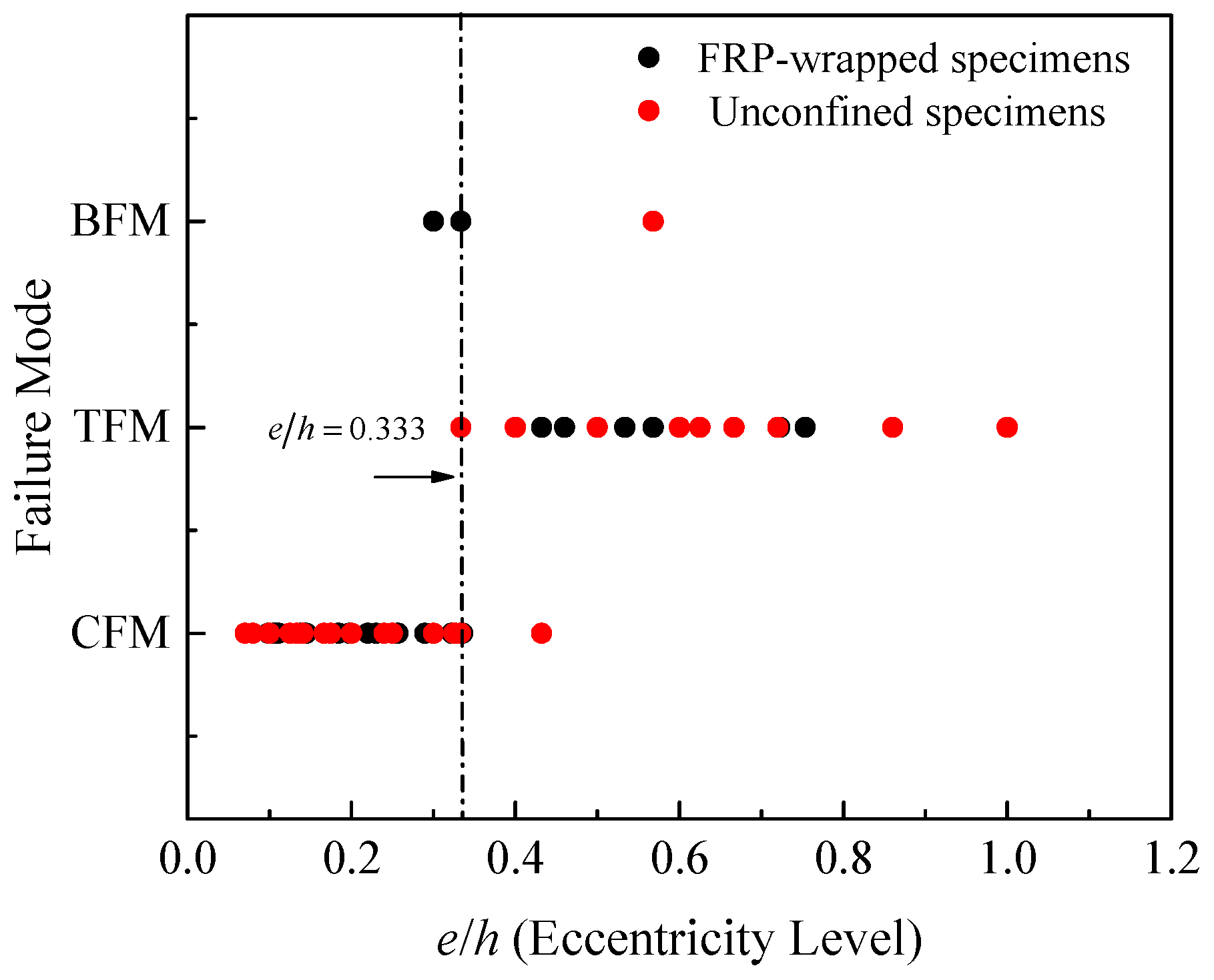
2.2. Failure Modes and Distribution of FRP Strains
3. Analytical Modeling
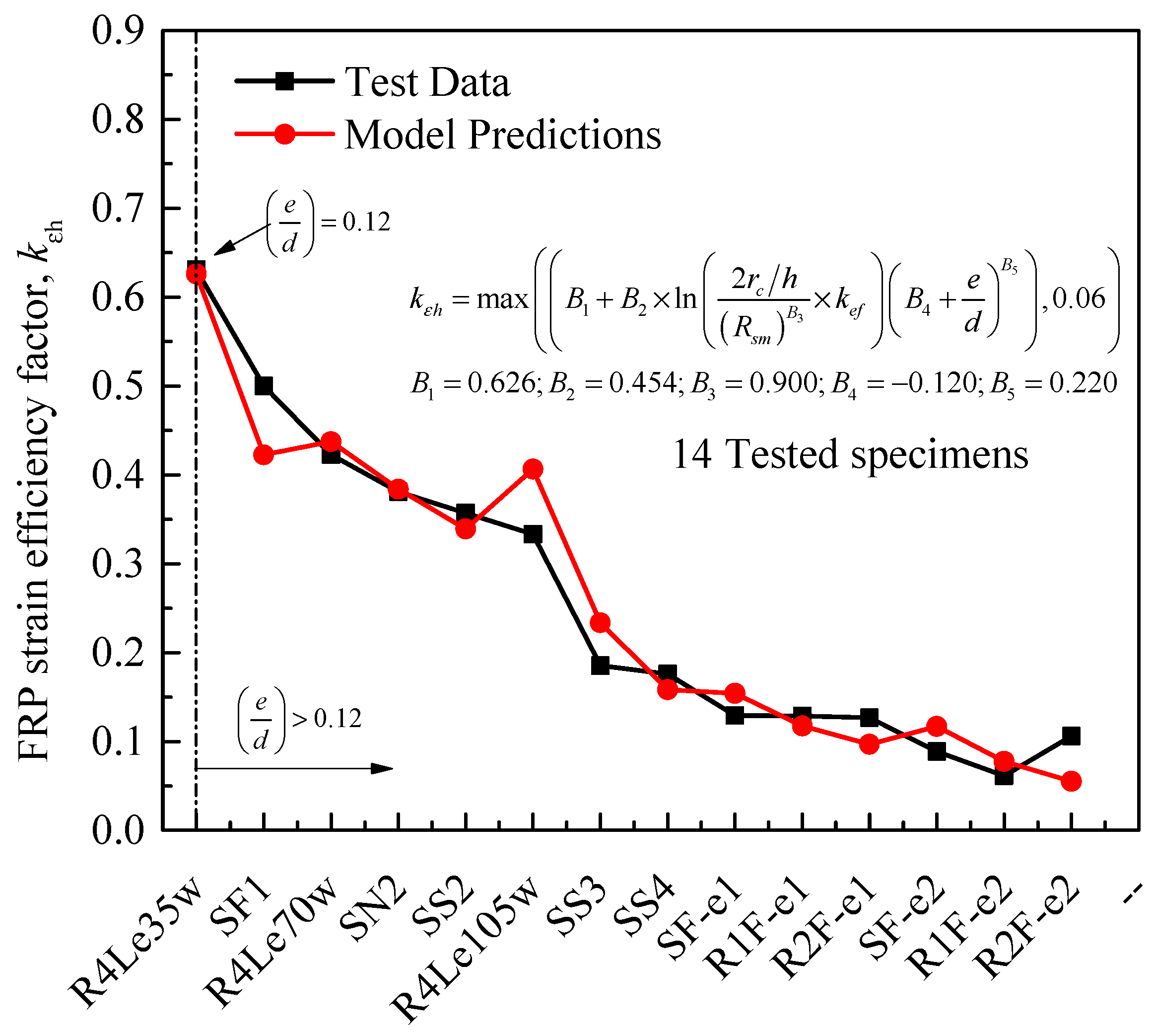
3.1. Rupture Strain of FRP in Rectangular Cross Sections
3.2. Modeling of Maximum Axial Capacity
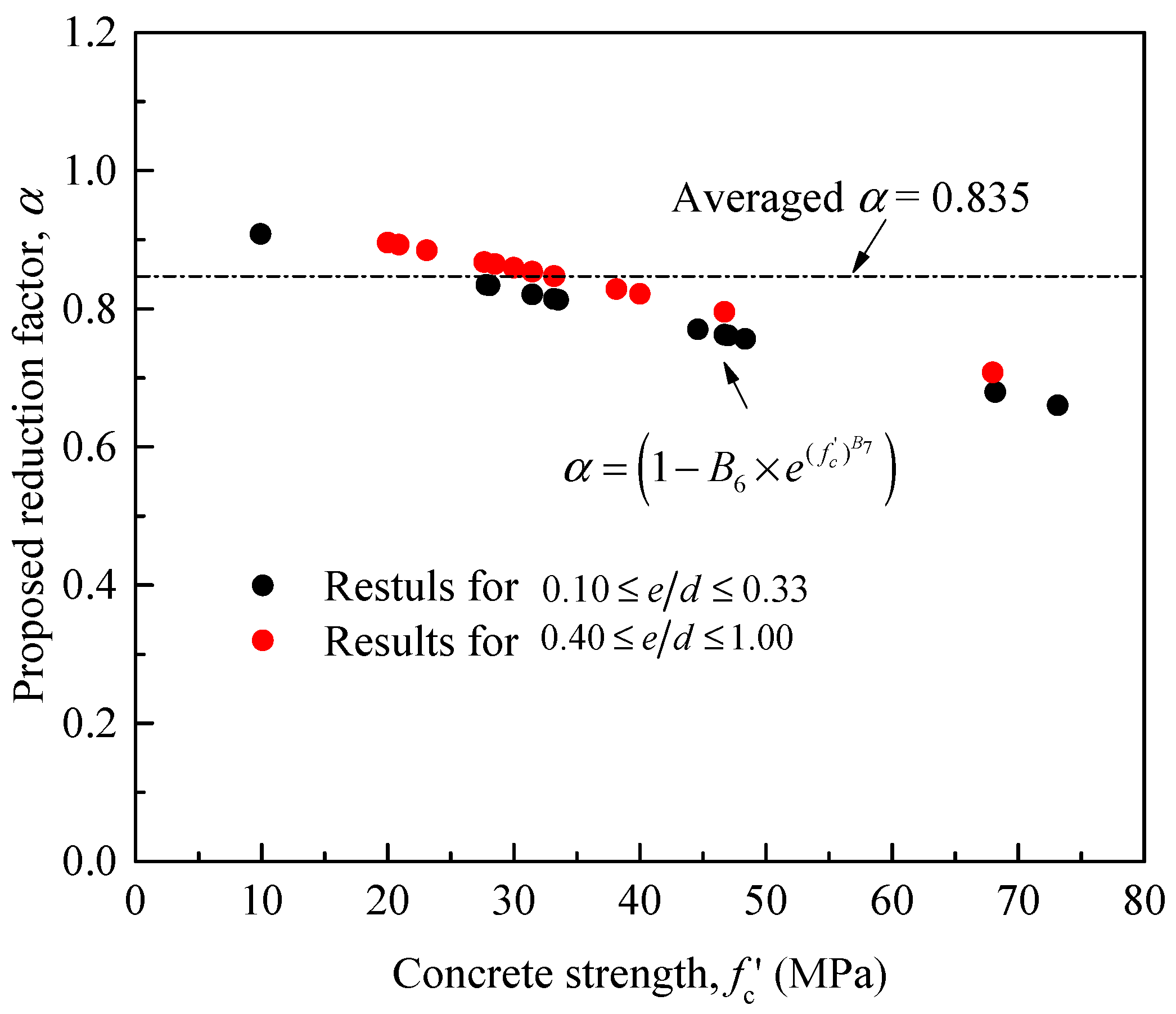
3.2.1. Equations for Unconfined RC Columns
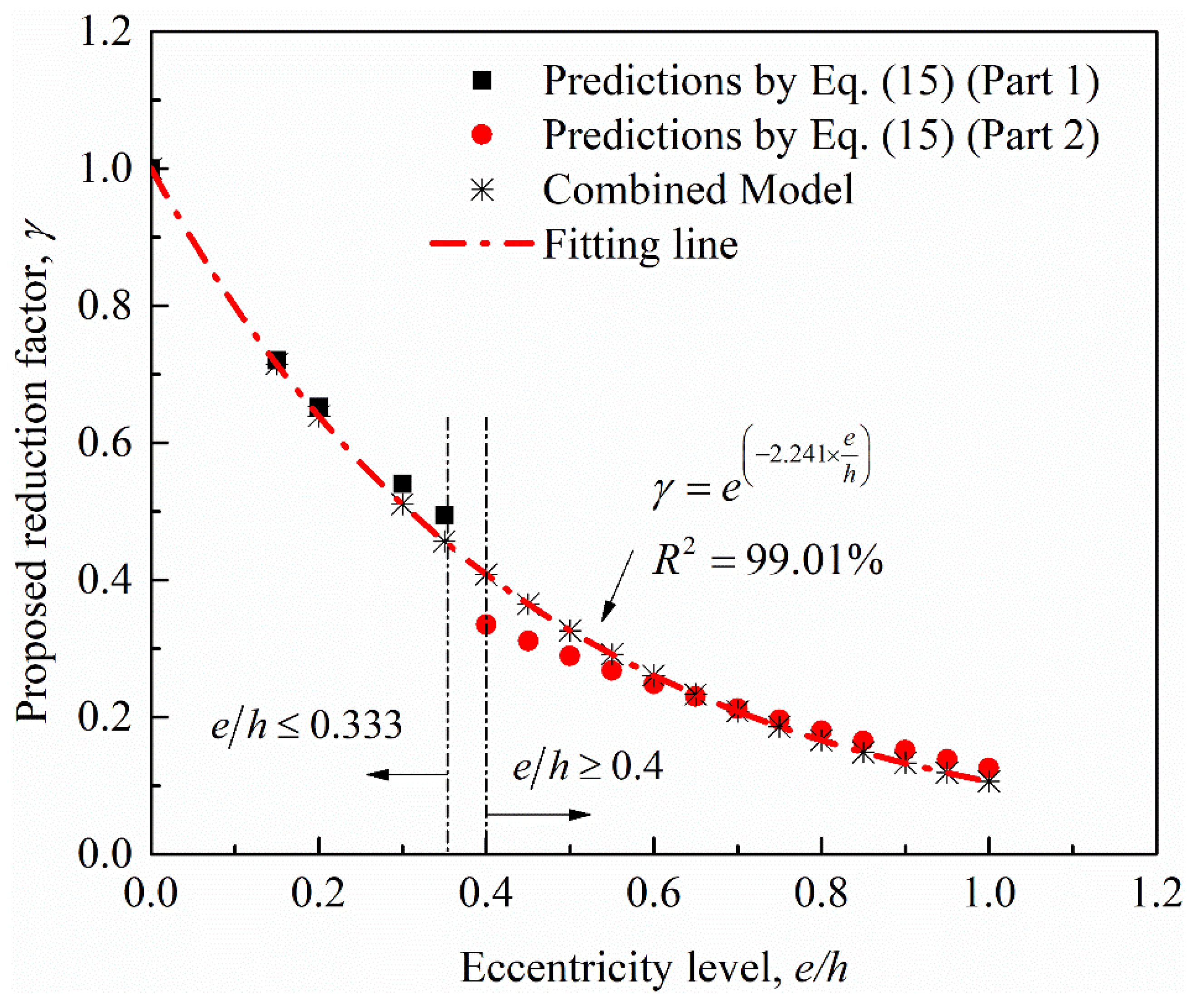
3.2.2. Equations for FRP-Confined RC Columns
3.3. Modeling of Axial Capacity at Failure
3.3.1. General
3.3.2. Equations for Unconfined RC Columns
3.3.3. Equations for FRP-Confined RC Columns
4. Conclusions
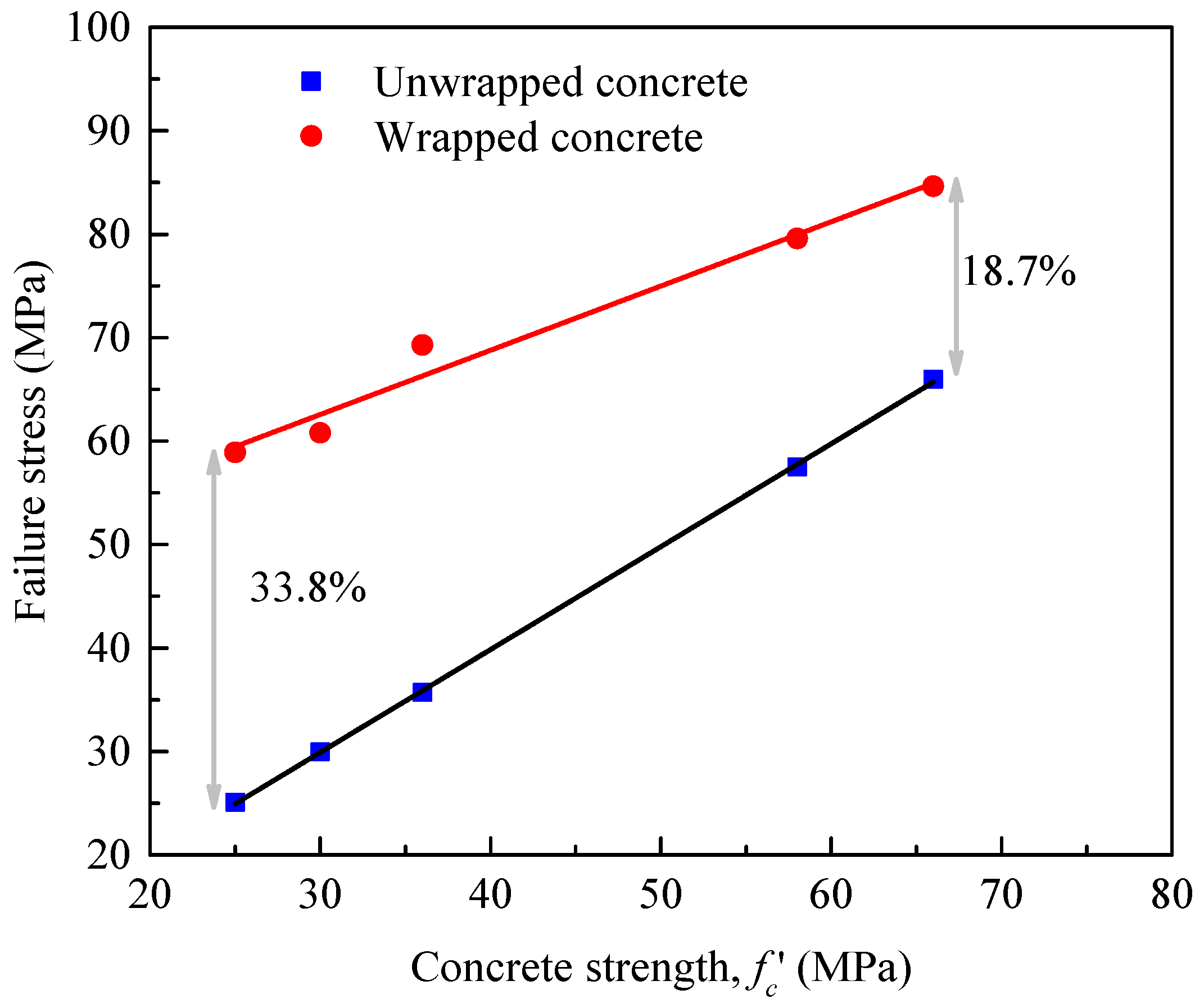
- Tests on eccentrically-loaded FRP-confined RC columns have shown the increase of the hoop steel reinforcement ratio increases the axial strength capacities. Tests have also shown that the confinement efficiency to decrease as the cross-sectional size and eccentric loading ratio increases.
- The actual rupture strain of the FRP wraps at the corners of the cross sections depends on the ratio of the corner radius to the cross-sectional depth and the eccentricity ratio in addition to the confinement stiffness ratio. Expressions for the actual strain of the FRP hoop at failure of eccentrically loaded RC columns were provided. The model presented in this study is based on limited column tests. Since the FRP hoop rupture strain is more sensitive to column parameters, further experimental and analytical research on tests considering the effects of wider ranges of test parameters to validate the application of the expressions may be necessary.
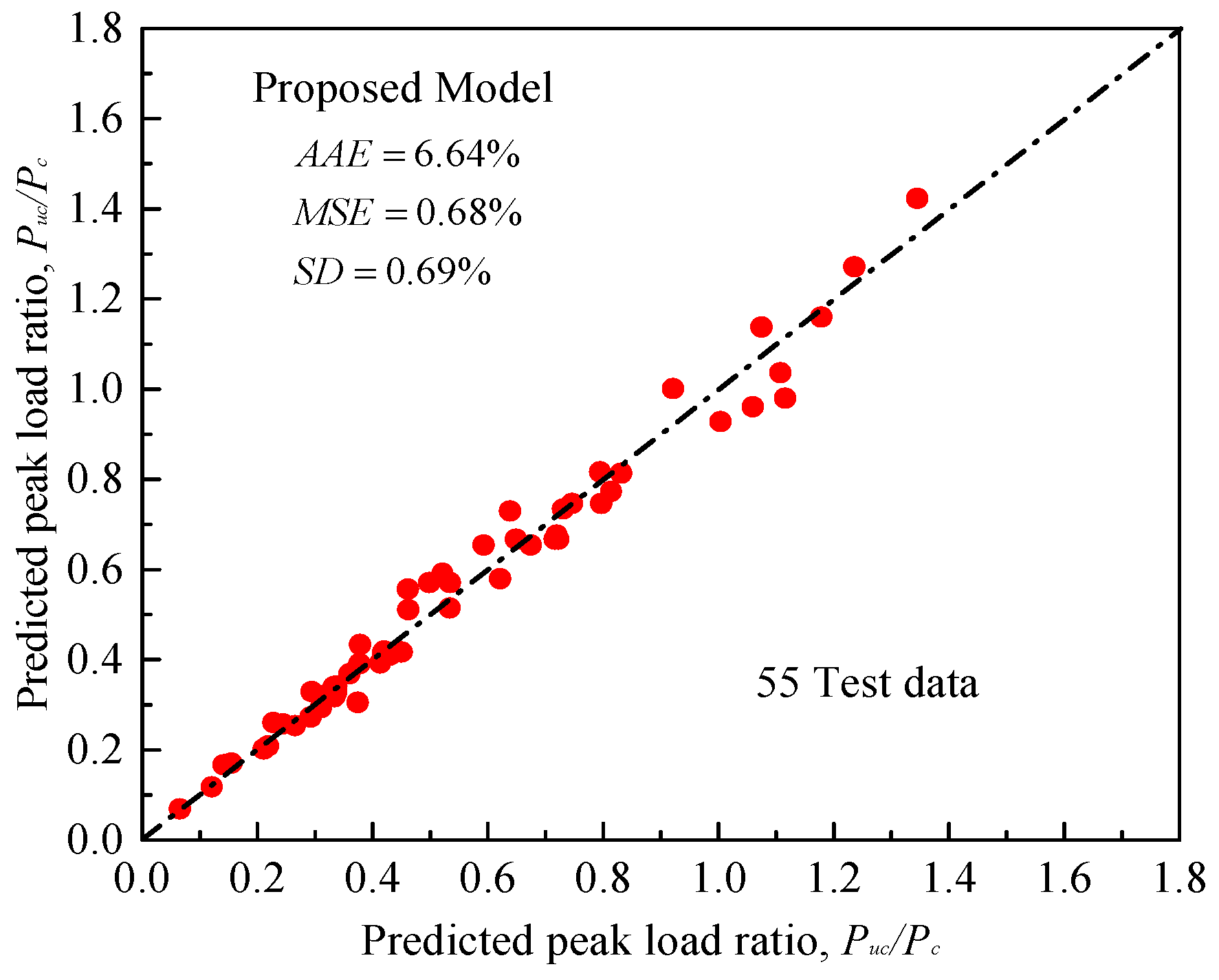
- For eccentric loads where the longitudinal steel reinforcement starts to yield in tension, the effect of confinement is of secondary importance. In such a case, the effectively confined core concrete area decreases as the eccentricity ratio increases. Therefore, it is now guaranteed by using the proposed model to choose a suitable reinforcement scheme (i.e., longitudinal CFRP strips) and number of CFRP layers for columns that can exhibit an ascending type of response.
Author Contributions
Funding
Institutional Review Board Statement
Informed Consent Statement
Data Availability Statement
Acknowledgments
Conflicts of Interest
Abbreviations
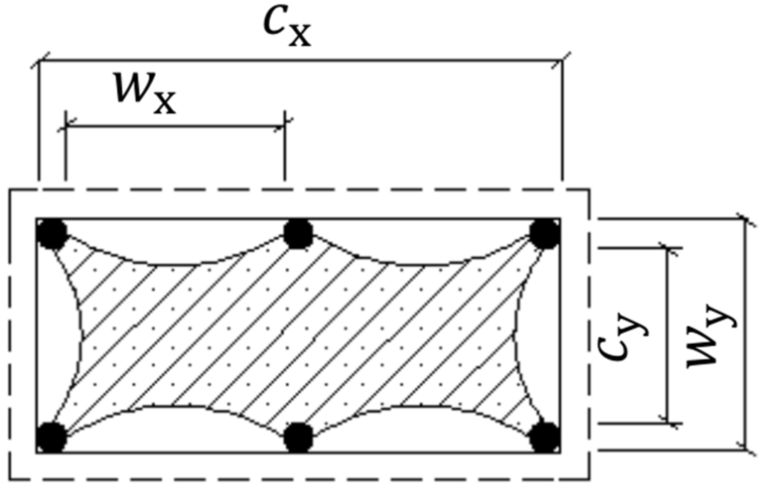
| & | width and depth of rectangular cross section, respectively (mm) |
| equivalent diameter of rectangular section (mm) | |
| corner radius (mm) | |
| area of rectangular cross section with rounded corners (mm2) | |
| clear height of column between end corbels | |
| total number of layers of full FRP wraps | |
| total number of layers of partial FRP wraps | |
| thickness of one FRP layer (mm) | |
| width of FRP strip (mm) | |
| center-to-center spacing of FRP strips (mm) | |
| elastic modulus of elasticity of FRP (MPa) | |
| tensile strength of FRP (MPa) | |
| volumetric ratio of FRP wraps | |
| coefficient for effectiveness of FRP wraps | |
| coefficient for effectiveness of internal steel ties | |
| strain efficiency factor of lateral FRP wraps | |
| strain efficiency factor of longitudinal FRP | |
| effective tensile strain of FRP at rupture | |
| ultimate tensile strain of FRP at rupture | |
| yield strength of hoop steel bars (MPa) | |
| yield strength of longitudinal steel bars (MPa) | |
| strength of unconfined concrete 150 mm × 300 mm cylinders (MPa) | |
| strength of unconfined concrete 100 mm × 200 mm cylinders (MPa) | |
| strength of unconfined concrete 150 mm × 150 mm cubes (MPa) | |
| unconfined concrete strain (mm/mm) | |
| shape factor to account for a rectangular cross section with rounded corners | |
| average absolute error | |
| mean square error | |
| standard deviation | |
| proposed confinement stiffness ratio of FRP in hoop axis | |
| proposed confinement stiffness ratio of FRP in vertical axis | |
| & | concrete core dimensions to the center line of the hoops along x and y directions (mm) |
| ratio of longitudinal reinforcement area divided by concrete core area | |
| & | cross-sectional areas of hoop reinforcement along x and y directions (mm2) |
| & | volumetric ratios of hoop reinforcement in x and y directions |
| effective volumetric ratio of steel ties | |
| & | clear distances between longitudinal bars along x and y directions (mm) |
| vertical clear spacing between steel ties (mm) | |
| center-to-center spacing between steel ties (mm) | |
| ratio of longitudinal steel reinforcement | |
| total area of longitudinal steel reinforcement (mm2) | |
| total number of tested specimens | |
| coefficient to account for the unconfined concrete strength effect | |
| coefficient to account for the effect of increased eccentricity ratio | |
| axial loading capacity of columns (KN) | |
| peak axial load of unwrapped RC columns (KN) | |
| peak axial load of FRP-wrapped columns (KN) | |
| failure axial load of unwrapped columns (KN) | |
| failure axial load of FRP-wrapped columns (KN) | |
| axial load of concrete cylinder (KN) | |
| proposed coefficient to account for the effect of FRP wrapping schemes |
References
- Rochette, P.; Labossière, P. Axial testing of rectangular column models confined with composites. J. Compos. Constr. 2000, 4, 129–136. [Google Scholar] [CrossRef]
- Lam, L.; Teng, J.G. Design-oriented stress–strain model for FRP-confined concrete in rectangular columns. J. Reinf. Plast. Compos. 2003, 22, 1149–1186. [Google Scholar] [CrossRef]
- Harris, K.A.; Carey, S.A. Shape and “gap” effect on the behavior of variably confined concrete. Cem. Concr. Res. 2003, 33, 881–890. [Google Scholar] [CrossRef]
- Rousakis, T.C.; Karabinis, A.I.; Kiousis, P.D. FRP-confined concrete members: Axial compression experiments and plasticity modeling. Eng. Struct. 2007, 29, 1343–1353. [Google Scholar] [CrossRef]
- Al-Salloum, Y.A. Influence of edge sharpness on the strength of square concrete columns confined with FRP composite laminates. Compos. Part B Eng. 2007, 38, 640–650. [Google Scholar] [CrossRef]
- Liu, P.; Gu, Z.; Peng, X.; Zheng, J. Finite element analysis of the influence of cohesive law parameters on the multiple delamination behaviors of composites under compression. Compos. Struct. 2015, 131, 975–986. [Google Scholar] [CrossRef]
- Panettieri, E.; Fanteria, D.; Danzi, F. Delaminations growth in compression after impact test simulations: Influence of cohesive elements parameters on numerical results. Compos. Struct. 2016, 137, 140–147. [Google Scholar] [CrossRef]
- Debski, H.; Rozylo, P.; Teter, A. Buckling and limit states of thin-walled composite columns under eccentric load. Thin-Walled Struct. 2020, 149, 106627. [Google Scholar] [CrossRef]
- Isleem, H.F.; Muhammed, T.; Wang, Z.Y. Axial stress-strain model developed for rectangular RC columns confined with CFRP wraps and anchors. Structures 2020, 23, 779–788. [Google Scholar] [CrossRef]
- Wang, Z.Y.; Wang, D.Y.; Smith, S.T.; Lu, D.G. CFRP-confined square RC columns. I: Experimental investigation. J. Compos. Constr. 2012, 16, 150–160. [Google Scholar] [CrossRef]
- Wang, Z.Y.; Wang, D.Y.; Smith, S.T.; Lu, D.G. CFRP-confined square RC columns. II: Cyclic axial compression stress-strain model. J. Compos. Constr. 2012, 16, 161–170. [Google Scholar] [CrossRef]
- Isleem, H.F.; Wang, D.Y.; Wang, Z.Y.; Smith, S.T. Monotonic and cyclic axial compressive behavior of CFRP-confined rectangular RC columns. J. Compos. Constr. 2018, 22, 04018023. [Google Scholar] [CrossRef]
- Isleem, H.F.; Wang, D.Y.; Wang, Z.Y. Modeling the axial compressive stress-strain behavior of CFRP-confined rectangular RC columns under monotonic and cyclic loading. Compos. Struct. 2018, 185, 229–240. [Google Scholar] [CrossRef]
- Isleem, H.F.; Wang, D.Y.; Wang, Z.Y. A new numerical model for polymer-confined rectangular concrete columns. Struct. Build. 2018. [Google Scholar] [CrossRef]
- Hadi, M.N.S. Comparative study of eccentrically loaded FRP wrapped columns. Compos. Struct. 2006, 74, 127–135. [Google Scholar] [CrossRef]
- Hadi, M.N.S. Behaviour of FRP wrapped normal strength concrete columns under eccentric loading. Compos. Struct. 2006, 72, 503–511. [Google Scholar] [CrossRef]
- Li, J.; Hadi, M.N.S. Behaviour of externally confined high-strength concrete columns under eccentric loading. Compos. Struct. 2003, 62, 145–153. [Google Scholar] [CrossRef]
- Hadi, M.N.S.M.; Widiarsa, I.B.R. Axial and flexural performance of square RC columns with CFRP under eccentric loading. J. Compos. Struct. 2012, 16, 640–649. [Google Scholar] [CrossRef] [Green Version]
- Maaddawy, T.E.; Sayed, M.E.; Abdel-Magid, B. The effects of cross-sectional shape and loading condition on performance of reinforced concrete members confined with carbon fiber-reinforced polymers. Mater. Des. 2010, 31, 2330–2341. [Google Scholar] [CrossRef]
- Lie, X.; Pham, T.M.; Lie, X.; Hadi, M.N.S. Effect of eccentric load on retrofitted reinforced concrete columns confined with FRP. Mech. Struct. Mater. ACMSM22 2013, 139–144. [Google Scholar]
- Hassan, W.M.; Hodhod, O.A.; Hilal, M.S.; Bahnasaway, H.H. Behavior of eccentrically loaded high strength concrete columns jacketed with FRP laminates. Constr. Build. Mater. 2017, 138, 508–527. [Google Scholar] [CrossRef]
- Yang, J.; Wang, J.; Wang, Z. Rectangular high-strength concrete columns confined with carbon fiber-reinforced polymer (CFRP) under eccentric compression loading. Constr. Build. Mater. 2018, 193, 604–622. [Google Scholar] [CrossRef]
- Pellegrino, C.; Modena, C. Analytical model for FRP confinement of concrete columns with and without internal steel reinforcement. J. Compos. Constr. 2010, 14, 693–705. [Google Scholar] [CrossRef]
- Ilki, A.; Peker, O.; Karamuk, E.; Demir, C.; Kumbasar, N. FRP retrofit of low and medium strength circular and rectangular reinforced concrete columns. J. Mater. Civ. Eng. 2008, 20, 169–188. [Google Scholar] [CrossRef]
- Luca, D.A.; Nardone, F.; Matta, F.; Nanni, A.; Lignola, G.P.; Prota, A. Structural evaluation of full-scale FRP-confined reinforced concrete columns. J. Compos. Constr. 2011, 15, 112–123. [Google Scholar] [CrossRef]
- Lin, G.; Yu, T.; Teng, J. Design-oriented stress-strain model for concrete under combined FRP-steel confinement. J. Compos. Constr. 2016, 20, 443–450. [Google Scholar] [CrossRef] [Green Version]
- Jaturapitakkul, C.; Kiattikomol, K.; Chucheepsakul, S.; Siripanichgorn, A. Effect of confinement on reinforced concrete columns subjected to eccentric loading. IABSE Rep. 1999, 81, 78–85. [Google Scholar]
- Song, X.; Gu, X.; Li, Y.; Chen, T.; Zhang, W. Mechanical behavior of FRP-strengthened concrete columns subjected to concentric and eccentric compression loading. J. Compos. Constr. 2013, 17, 336–346. [Google Scholar] [CrossRef]
- Maaddawy, T.E. Strengthening of eccentrically loaded reinforced concrete columns with fiber-reinforced polymer wrapping system: Experimental investigation and analytical modeling. J. Compos. Constr. 2009, 13, 13–24. [Google Scholar] [CrossRef]
- Hu, B.; Wang, J.-G.; Li, G.-Q. Numerical simulation and strength models of FRP-wrapped reinforced concrete columns under eccentric loading. Constr. Build. Mater. 2011, 25, 2751–2763. [Google Scholar] [CrossRef]
- Pour, A.F.; Gholampour, A.; Zheng, J.; Ozbakkaloglu, T. Behavior of FRP-confined high-strength concrete under eccentric compression: Tests on concrete-filled FRP tube columns. Compos. Struct. 2019, 220, 261–272. [Google Scholar] [CrossRef]
- Al-Nimry, H.; Neqresh, M. Confinement effects of unidirectional CFRP sheets on axial and bending capacities of square RC columns. Eng. Struct. 2019. [Google Scholar] [CrossRef]
- Darby, A.P.; Coonan, R.; Tim, I.; Mark, E. FRP confined square columns under concentric and eccentric loading. In Proceedings of the 5th International Conference on Advanced Composite in Construction, Warwick, UK, 6–8 September 2011. [Google Scholar]
- Shaikh, F.U.A.; Alishahi, R. Behaviour of CFRP wrapped RC square columns under eccentric compressive loading. Structures 2019, 20, 309–323. [Google Scholar] [CrossRef]
- Allawi, A.A.; Sarsam, K.F.; Hassan, R.F. Behavior of Strengthened RC Short Columns with CFRP under Eccentric Load. In Proceedings of the 7th Asia Pacific Young Researchers and Graduates Symposium, Innovations in Materials and Structural Engineering Practices, Kuala Lumpur, Malaysia, 21–28 August 2015. [Google Scholar]
- Sadeghian, P.; Rahai, A.; Ehsani, M. Experimental study of rectangular RC columns strengthened with CFRP composites under eccentric loading. J. Compos. Constr. 2010, 14, 443–450. [Google Scholar] [CrossRef]
- Saljoughian, A.; Mostofinejad, D. Axial-flexural interaction in square RC columns confined by intermittent CFRP wraps. Compos. Part B Eng. 2016, 89, 85–95. [Google Scholar] [CrossRef]
- Taranu, N.; Cozmanciuc, C.; Oltean, R. Experimental study of reinforced concrete columns confined with composite membranes. Buletinul. Institutului. Politehnic. Din. Iaşi. 2011, 57, 33–45. [Google Scholar]
- Xian, Q.L.; Yi, W.J.; Ding, H.T. Experiment and research of reinforced concrete column externally bonded with CFRP sheets under eccentric load. Indus. Constr. 2004, 34, 78–81. (In Chinese) [Google Scholar]
- Elsayed, M.; Elassaly, M.; Esmail, W. Behavior of eccentrically loaded RC columns confined with CFRP composites. Inter. Res. J. Eng. Tech. IRJET 2018, 5, 1336–1343. [Google Scholar]
- Zhou, C.D.; Huang, C.K. Investigation of mechanical behavior of RC columns strengthened with glass fiber-reinforced polymer under eccentric loading. Eng. Mech. 2004, 21, 87–93. (In Chinese) [Google Scholar]
- Jinglong, P.; Wei, W.; Xinan, J.; Chenyuan, W. A study on the properties of a FRP-confined short reinforced concrete column subjected to eccentric loading. China Civ. Eng. J. 2005, 38, 46–50. (In Chinese) [Google Scholar]
- Lin, G.; Zeng, J.J.; Teng, J.G.; Li, L.J. Behavior of large-scale FRP-confined rectangular RC columns under eccentric compression. Eng. Struct. 2020, 216, 110759. [Google Scholar] [CrossRef]
- Lam, L.; Teng, J.G. Strength models for fiber-reinforced plastic-confined concrete. J. Struct. Eng. 2002, 128, 612–623. [Google Scholar] [CrossRef]
- Abbasnia, R.; Ahmadi, R.; Ziaadiny, H. Effect of confinement level, aspect ratio and concrete strength on the cyclic stress–strain behavior of FRP-confined concrete prisms. Compos. Part B Eng. 2012, 43, 825–831. [Google Scholar] [CrossRef]
- Pham, T.M.; Hadi, M.N.S. Confinement model for FRP confined normal- and high-strength concrete circular columns. Constr. Build. Mater. 2014, 69, 83–90. [Google Scholar] [CrossRef] [Green Version]
- ACI. Guide for the Design and Construction of Externally Bonded FRP Systems for Strengthening Concrete Structure; ACI 440.2R-08; ACI Committee 440; American Concrete Institute: Farmington Hills, MI, USA, 2008. [Google Scholar]
- Cheng, S.; Feng, P.; Bai, Y.; Ye, L.P. Load-strain model for steel-concrete-FRP-concrete columns in axial compression. J. Compos. Constr. 2016, 20, 04016017. [Google Scholar] [CrossRef]
- Reddy, V.S.; Rao, M.V.S.; Shrihari, S. Strength conversion factors for concrete based on specimen geometry, aggregate size and direction of loading. Int. J. Rec. Tech. Eng. IJRTE 2019, 8, 2125–2130. [Google Scholar]
- Chaallal, O.; Hassan, M.; Shahawy, M. Confinement model for axially loaded short rectangular columns strengthened with fiber-reinforced polymer wrapping. ACI Struct. J. 2003, 100, 215–221. [Google Scholar]
- Pham, T.M.; Hadi, M.N.S. Stress prediction model for FRP confined rectangular concrete columns with rounded corners. J. Compos. Constr. 2014, 18, 113–124. [Google Scholar] [CrossRef] [Green Version]
- Hadi, M.N.S.; Pham, T.M.; Lei, X. New method of strengthening reinforced concrete square columns by circularizing and wrapping with fiber-reinforced polymer or steel straps. J. Compos. Constr. 2013, 229–238. [Google Scholar] [CrossRef]
- Campione, G.; Miraglia, N. Strength and strain capacities of concrete compression members reinforced with FRP. Cem. Concr. Compos. 2003, 25, 31–41. [Google Scholar] [CrossRef]
- Barrington, J.; Dickson, D.; Bisby, L.; Stratford, T. Strain development and hoop strain efficiency in FRP confined square columns. In Proceedings of the FRPRCS 10, Tampa, FL, USA, 2–4 April 2011. [Google Scholar]
- Wang, L.M.; Wu, Y.F. Effect of corner radius on the performance of CFRP-confined square concrete columns: Test. Eng. Struct. 2008, 30, 493–505. [Google Scholar] [CrossRef]
- Yan, Z.H. Shape Modification of Rectangular Columns Confined with FRP Composites. Ph.D. Thesis, University of Utah, Salt Lake Country, UT, USA, 2005. [Google Scholar]
- Teng, J.G.; Jiang, T.; Lam, L.; Luo, Y.Z. Refinement of a design-oriented stress-strain model for FRP-confined concrete. J. Compos. Constr. 2009, 269–278. [Google Scholar] [CrossRef] [Green Version]
- Tasdemir, M.A. Evaluation of strains at peak stresses in concrete: A three-phase composite model approach. Cem. Concr. Compos. 1998, 20, 301–318. [Google Scholar] [CrossRef]
- ACI. Guide for the Design and Construction of Externally Bonded FRP Systems for Strengthening Concrete Structures; Technical Committee Document 400.2R-02; ACI Committee 440; American Concrete Institute: Farmington Hills, MI, USA, 2004. [Google Scholar]
- Ozbakkaloglu, T. Behavior of square and rectangular ultra high-strength concrete-filled FRP tubes under axial compression. Compos. Part B Eng. 2013, 54, 97–111. [Google Scholar] [CrossRef]
- Hany, N.F.; Hantouche, E.G.; Harajli, M. Axial stress-strain model of CFRP-confined concrete under monotonic and cyclic loading. J. Compos. Constr. 2015, 16, 1–16. [Google Scholar] [CrossRef]
- Wang, D.Y.; Wang, Z.Y.; Smith, S.T.; Yu, T. Size effect on axial stress-strain behavior of CFRP-confined square concrete columns. Constr. Build. Mater. 2016, 18, 116–126. [Google Scholar] [CrossRef]
- ACI. Guide for the Design and Construction of Externally Bonded FRP Systems for Strengthening Concrete Structures; ACI 440.2R; American Concrete Institute: Farmington Hills, MI, USA, 2017; ISBN 978-1-945487-59-0. [Google Scholar]
- Soudki, K.; Alkhrdaji., T. Guide for the design and construction of externally bonded FRP systems for strengthening concrete structures (ACI 440.2 R-02). In Proceedings of the Structures Congress 2005: Metropolis and Beyond, New York, NY, USA, 20–24 April 2005; pp. 1–8. [Google Scholar]
- Wang, C.K.; Pincheira, J.A.C.D. Reinforced Concrete Design; Wiley: Hoboken, NJ, USA, 2007. [Google Scholar]
- ACI. Building Code Requirements for Structural Concrete and Commentary; American Concrete Institute: Farmington Hills, MI, USA, 1995. [Google Scholar]
- Mirmiran, A.; Shahawy, M.; Samaan, M.; El-Echary, H.E.; Mastrapa, J.C.; Pico, O. Effect of column parameters on FRP-confined concrete. J. Compos. Constr. 1998, 2, 175–185. [Google Scholar] [CrossRef]
- Bisby, L.; Ranger, M. Axial-flexural interaction in circular FRP-confined reinforced concrete columns. Constr. Build. Mater. 2010, 24, 1672–1681. [Google Scholar] [CrossRef]
- Sheikh, S.A.; Uzumeri, S.M. Analytical model for concrete confinement in tied columns. J. Struct. Div. 1982, 108, 2703–2722. [Google Scholar] [CrossRef]
- Vincent, T.; Ozbakkaloglu, T. Influence of concrete strength and fibre type on the compressive behaviour of FRP-confined high-strength concrete. In Proceedings of the 9th International Symposium on Fiber-Reinforced Polymer Reinforcement for Concrete Structures (FRPRCS-9), Sydney, Australia, 13–15 July 2009. [Google Scholar]
- Eid, R.; Roy, N.; Paultre, P. Normal- and high-strength concrete circular elements wrapped with FRP composites. J. Compos. Constr. 2009, 13, 113–124. [Google Scholar] [CrossRef]
- Wu, H.; Wang, Y.; Yu, L.; Li, X. Experimental and computational studies on high strength concrete circular columns confined by aramid fiber-reinforced polymer sheets. J. Compos. Constr. 2009, 13, 125–134. [Google Scholar] [CrossRef]
- Daugevičius, M.; Valivonis, J.; Beinaravičius, A.; Skuturna, T.; Budvytis, M. Experimental investigation of the load carrying capacity of eccentrically loaded reinforced concrete elements strengthened with CFRP. Proc. Eng. 2013, 57, 232–237. [Google Scholar] [CrossRef] [Green Version]
- ACI. Building Code Requirements for Structural Concrete and Commentary; ACI Committee (318-14); American Concrete Institute: Farmington Hills, MI, USA, 2014. [Google Scholar]
- ACI. Building Code Requirements for Structural Concrete and Commentary; ACI 318-08; American Concrete Institute: Farmington Hills, MI, USA, 2008. [Google Scholar]
- Standards Australia. Concrete Structures; AS3600-2009; Standards Australia: Sydney, Australia, 2009. [Google Scholar]
- CSA. Design and Construction of Building Components with Fiber Reinforced Polymers (S806-12); Canadian Standards Association: Rexdale, ON, Canada, 2012. [Google Scholar]
- Ranger, M.; Bisby, L. Effects of load eccentricities on circular FRP confined reinforced concrete columns. In Proceedings of the 8th International Symposium on Fiber-Reinforced Polymer Reinforcement for Concrete Structures, Patras, Greece, 16–18 July 2007. [Google Scholar]
- Rocca, S.; Galati, N.; Nanni, A. Interaction diagram methodology for design of FRP-confined reinforced concrete columns. Constr. Build. Mater. 2009, 23, 1508–1520. [Google Scholar] [CrossRef]
- Hadi, M.N.; Yazici, V. Behaviour of FRP wrapped circular reinforced concrete columns. In Challenges, Opportunities and Solutions in Structural Engineering and Construction, Proceedings of the 5th International Structural Engineering and Construction Conference, Las Vegas, NV, USA, 21–27 September 2009; Ghafoori, N., Ed.; CRC Press: London, UK, 2009. [Google Scholar]
- Hadi, M.N.S. Behaviour of eccentric loading of FRP confined fibre steel reinforced concrete columns. Constr. Build. Mater. 2009, 23, 1102–1108. [Google Scholar] [CrossRef] [Green Version]
- Bank, L.C. Composites for Construction: Structural Design with FRP Materials; John Wiley & Sons: Hoboken, NJ, USA, 2006. [Google Scholar]
- Al-Nimry, H.; Soman, A. On the slenderness and FRP confinement of eccentrically-loaded circular RC columns. Eng. Struct. 2018, 164, 92–108. [Google Scholar] [CrossRef]
- Al-Nimry, H.S.; Al-Rabadi, R.A. Axial-flexural interaction in FRP-wrapped RC columns. Int. J. Conc. Struct. Mater. 2019. [Google Scholar] [CrossRef]
- Wu, Y.; Jiang, C. Effect of load eccentricity on the stress-strain relationship of FRP-confined concrete columns. Compos. Struct. 2013, 98, 228–241. [Google Scholar] [CrossRef]
- Fahmy, M.; Farghal, O. Eccentricity-based design-oriented model of fiber-reinforced polymer-confined concrete for evaluation of load-carrying capacity of reinforced concrete rectangular columns. J. Reinf. Plast. Compos. 2016, 35, 1734–1758. [Google Scholar] [CrossRef]
- Wu, Y.F.; Cao, Y.G. Effect of load path on behavior of FRP-confined concrete. J. Compos. Constr. 2017, 21, 1–16. [Google Scholar] [CrossRef]
- Cao, Y.G.; Wu, Y.F.; Jiang, C. Stress-strain relationship of FRP confined concrete columns under combined axial load and bending moment. Compos. Part B Eng. 2018, 134, 207–217. [Google Scholar] [CrossRef]
- Mohamed, A.M.; Oehlers, D.; Griffith, M. The Residual Strength of Confined Concrete. Adv. Struct. Eng. 2010, 13, 603–618. [Google Scholar]
- Bisby, L.; Li, S.; Duerden, B.; Mclarty, K.; Chen, J.F.; Stratford, T. Effects of Unconfined Concrete Strength on FRP Confinement of Concrete; University of Edinburgh: Edinburgh, UK, 2005. [Google Scholar]
- Mandal, S.; Hoskin, A.; Fam, A. Influence of concrete strength on confinement effectiveness of fiber-reinforced polymer circular jackets. ACI Struct. J. 2005, 102, 383–392. [Google Scholar]
- Doan, L.; Lei, X.; Pham, T.; Hadi, M. Confinement effect of FRP and transverse steel on retrofitting square concrete columns. In Proceedings of the Fourth Asia-Pacific Conference on FRP in Structures, Melbourne, Australia, 11–13 December 2013. [Google Scholar]
- Wasim, M.; Ngo, T.D.; Abid, M. Investigation of long-term corrosion resistance of reinforced concrete structures constructed with various types of concretes in marine and various climate environments. Constr. Build. Mater. 2020, 237, 117701. [Google Scholar] [CrossRef]


| Proposed Model Influence Factor | ||||||||
|---|---|---|---|---|---|---|---|---|
| FRP Confining Stress | Shape Factor | Corner Radius | FRP Effective Strain | FRP Ratio | Eccentricity Level | Hoop Steel | Slenderness Ratio | Section Size |
| Currently proposed | ||||||||
| Yes | Yes | Yes | Yes | Yes | Yes | Yes | Yes | Yes |
| El Maaddawy [29] | ||||||||
| Yes | Yes | No | No | Yes | Yes | No | No | No |
| Hu et al. [30] | ||||||||
| Yes | Yes | No | No | Yes | Yes | No | Yes | No |
| Yang et al. [22] | ||||||||
| Yes | Yes | Yes | Yes | Yes | No | No | No | No |
| Pour et al. [31] | ||||||||
| No | No | Yes | No | No | Yes | No | No | No |
| Al-Nimry and Neqresh [32] | ||||||||
| Yes | Yes | No | Yes | Yes | No | No | No | No |
| Research Study | Specimens Number, N | Confinement Technique | Wrapping Mode | Width, b: mm | Depth, h: mm | Height, H: mm | Corner Radius, rc: mm | Cylinder Concrete Strength, fc | Maximum Load (KN) | Failure Load (KN) |
|---|---|---|---|---|---|---|---|---|---|---|
| Jaturapitakkul et al. [27] | 10 | Hoop reinforcement | - | 200 | 300 | 1200 | - | 9.9 | 423.4–791.9 | - |
| Al-Nimry and Neqresh [32] | 18 | CFRP/hoop reinforcement | Full | 200 | 200 | 1200 | 12.5 | 43.8–52.4 | 917.6–1903 | 735.2–1552.3 |
| Darby et al. [33] | 5 | CFRP | Full | 150 | 150 | 925–1250 | 20 | 28.1–31.5 | 184–812 | - |
| Shaikh and Alishahi [34] | 12 | CFRP/hoop reinforcement | Full | 175 | 175 | 800 | 20 | 47 | 654–1320 | 403.4–1122.8 |
| Hassan et al. [21] | 6 | E-Glass/hoop reinforcement | Partial & Full | 200 | 200 | 1850 | 13 | 68–72.1 | 322–2005 | 350.3–1959.5 |
| Song et al. [28] | 8 | CFRP | Full | 250 | 250 | 1500 | 25 | 20 | 384–1214 | 322.3–1145.1 |
| Hadi et al. [18] | 2 | Hoop reinforcement | - | 200 | 200 | 800 | - | 73.1 | 1336–1950 | 413–467 |
| Allawi et al. [35] | 7 | CFRP/hoop reinforcement | Full | 150 | 150 | 700 | 10 | 33.2 | 159–750.8 | 139.9–622.1 |
| El Maaddawy et al. [29] | 9 | CFRP/hoop reinforcement | Partial & Full | 125 | 125 | 1200 | 10 | 28.5 | 92–205 | - |
| Sadeghian et al. [36] | 6 | CFRP/hoop reinforcement | Full | 200 | 300 | 2700 | 15 | 40 | - | 156-600 |
| Saljoughian and Mostofinejad [37] | 6 | CFRP/hoop reinforcement | Partial | 133 | 133 | 500 | 8 | 30 | 80.7–235.3 | 61–197.1 |
| El Maaddawy et al. [19] | 12 | CFRP/hoop reinforcement | Full | 110–135 | 135–160 | 1300–1400 | 10 | 20 | 105.3–190.2 | - |
| Taranu et al. [38] | 4 | CFRP/hoop reinforcement | Full | 250–300 | 250–300 | 1000 | 35 | 30 | 2004.9–2480.7 | 1988.4–2419.3 |
| Xian et al. [39] | 20 | CFRP/hoop reinforcement | Partial | 250 | 350 | 2200 | 13 | 17.7–40.5 | 640-2390 | - |
| Yang et al. [22] | 14 | CFRP/hoop reinforcement | Partial & Full | 150 | 200 | 1200 | 15 | 46.7 | 401.5–1004.9 | 340.9–854.3 |
| Elsayed et al. [40] | 3 | CFRP/hoop reinforcement | Partial & Full | 100 | 150 | 1700 | 20 | 20.6 | 258–296 | 224.3–248.9 |
| Zhou and Huang [41] | 7 | CFRP/hoop reinforcement | Partial & Full | 150 | 200 | 1200 | 20 | 33.2 | 328.5–878 | - |
| Jinglong et al. [42] | 3 | CFRP/hoop reinforcement | Full | 120 | 150 | 950 | 15 | 26.6–27.7 | 163–621 | - |
| Lin et al. [43] | 3 | CFRP/hoop reinforcement | Full | 290 | 435 | 1300 | 35 | 45 | 2693.9–5123.2 | - |
| Source | Longitudinal Steel fyl (MPa) | Hoop Steel fyh (MPa) | FRP Material | |||
|---|---|---|---|---|---|---|
| Ef (GPa) | ff (MPa) | tf (mm) | εfu (%) | |||
| Jaturapitakkul et al. [27] | 282.8 (Φ12) | 283.2 (Φ6) | - | - | - | - |
| Al-Nimry and Neqresh [32] | 420 (Φ10) | 570 (Φ6) | 240 | 3800 | 0.170 | 1.55 |
| Darby et al. [33] | 550 (Φ12) | - | 214 | 3103 | 0.160 | 1.45 |
| Shaikh and Alishahi [34] | 500 (Φ12) | 500 (Φ6) | 230 | 3450 | 0.130 | 1.50 |
| Hassan et al. [21] | 400 (Φ16) | 240 (Φ8) | 70 | 2250 | 0.170 | 2.80 |
| Song et al. [28] | 337.6 (Φ14) | 421.9 (Φ6) | 222 | 3500 | 0.167 | 1.70 |
| Hadi et al. [18] | 564 (Φ12) | 516 (Φ8) | - | - | - | - |
| Allawi et al. [35] | 566-652 (Φ12) | 566 (Φ6) | 230 | 3450 | 0.130 | 1.50 |
| El Maaddawy et al. [29] | 550 (Φ10) | 550 (Φ6) | 230 | 3450 | 0.130 | 1.50 |
| Sadeghian et al. [36] | 465 (Φ12) | 325 (Φ6.5) | 242 | 3860 | 0.250 | 1.60 |
| Saljoughian and Mostofinejad [37] | 406 (Φ10) | 550 (Φ8) | 230 | 3900 | 0.170 | 1.50 |
| El Maaddawy et al. [19] | 520 (Φ10) | 300 (Φ6) | 230 | 3450 | 0.130 | 1.50 |
| Yang et al. [22] | 403.7 (Φ14) | 365.3 (Φ6) | 240 | 4250 | 0.167 | 1.77 |
| Taranu et al. [38] | 300 (Φ12) | 210 (Φ6) | 234.5 | 3793 | 0.340 | 1.50 |
| Xian et al. [39] | 365 (Φ18) | 365 (Φ8) | 230 | 4700 | 0.111 | 2.00 |
| Elsayed et al. [40] | 420 (Φ12) | 290 (Φ8) | 240 | 3800 | 0.170 | 1.55 |
| Zhou and Huang [41] | 365.9 (Φ14) | 361.6 (Φ6) | 87.7 | 2800 | 0.169 | 3.20 |
| Jinglong et al. [42] | 445 (Φ10) | 445 (Φ4) | 230 | 4700 | 0.111 | 2.00 |
| Lin et al. [43] | 491 (Φ20) | 380 (Φ8) | 238.8 | 3993.3 | 0.334 | 1.68 |
| Equation (13): Strain Efficiency Factor of FRP in Hoop Axis | ||||||
| B1 | B2 | B3 | B4 | B5 | B6 | B7 |
| 0.626 | 0.454 | 0.900 | −0.120 | 0.220 | 0.06 | - |
| Equation (14): Strain efficiency factor of FRP in longitudinal axis | ||||||
| B1 | B2 | B3 | B4 | B5 | B6 | B7 |
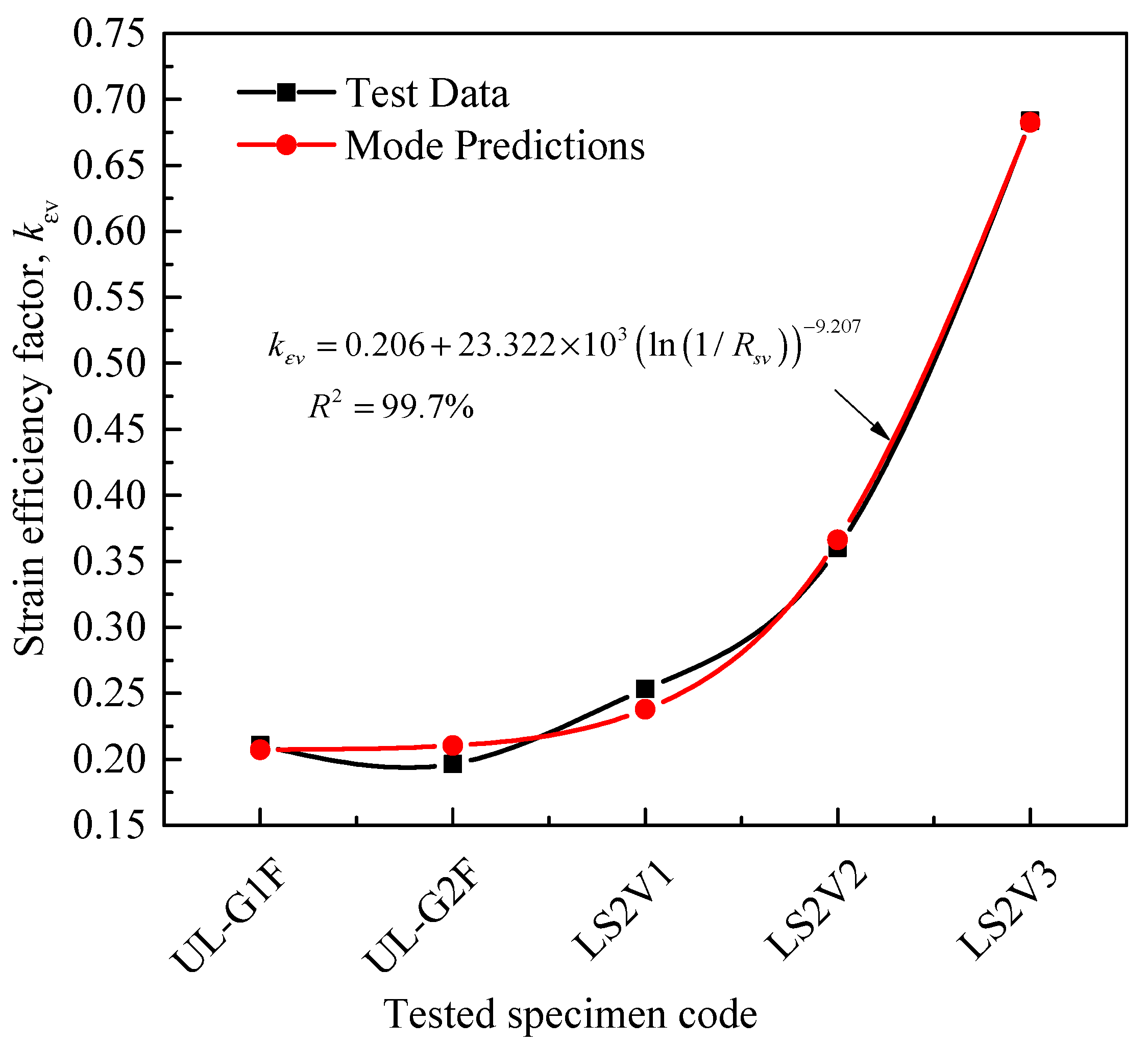
| 0.205 | 10.2660 | −9.097 | 0.678 | - | - | - |
| Equation (15): Peak load ratio of unwrapped RC columns (0.1 ≤ e/h ≤ 0.33) | ||||||
| B1 | B2 | B3 | B4 | B5 | B6 | B7 |
| 2.601 | 0.379 | 12.086 | 3.060 | −2.348 | 0.014 | 0.268 |
| Equation (15): Peak load ratio of unwrapped RC columns (0.4 ≤ e/h ≤ 1) | ||||||
| B1 | B2 | B3 | B4 | B5 | B6 | B7 |
| −0.390 | −0.524 | 2.367 | 2.801 | −0.956 | 0.009 | 0.292 |
| Equation (22): Peak load ratio of FRP-wrapped RC columns | ||||||
| B1 | B2 | B3 | B4 | B5 | B6 | B7 |
| 2.120 | 0.719 | 3.304 | 0.613 | 0.377 | −3.333 | 3.238 × 10⁻³ |
| Equation (25): Failure load ratio of unwrapped RC columns | ||||||
| B1 | B2 | B3 | B4 | B5 | B6 | B7 |
| 1.683 | 0.225 | −1.563 | 1.212 | - | - | - |
| Equation (26): Failure load ratio of FRP-wrapped RC columns | ||||||
| B1 | B2 | B3 | B4 | B5 | B6 | B7 |
| 0.304 | 0.355 | −1.296 | 6.716 | 0.771 | −1.670 | - |
| Model | Prediction of kεh | Prediction of kεv | ||||||
|---|---|---|---|---|---|---|---|---|
| Averaged (Model/Test) (%) | Average Absolute Error (%) | Mean (%) | Standard Deviation (%) | Averaged (Model/Test) (%) | Average Absolute Error (%) | Mean (%) | Standard Deviation (%) | |
| Currently proposed | 99.95 | 17.20 | 4.67 | 22.42 | 100 | 3.34 | 0.19 | 4.83 |
| Barrington et al. [54] | 94.27 | 79.18 | 108.60 | 110.90 | - | - | - | - |
| Wang et al. [11] | 215.06 | 264.12 | 1318.48 | 303.77 | - | - | - | - |
| Hadi et al. [51] | 189.10 | 195.49 | 739.90 | 226.07 | - | - | - | - |
| Ozbakkaloglu [60] | 250.56 | 307.13 | 1756.29 | 337.40 | - | - | - | - |
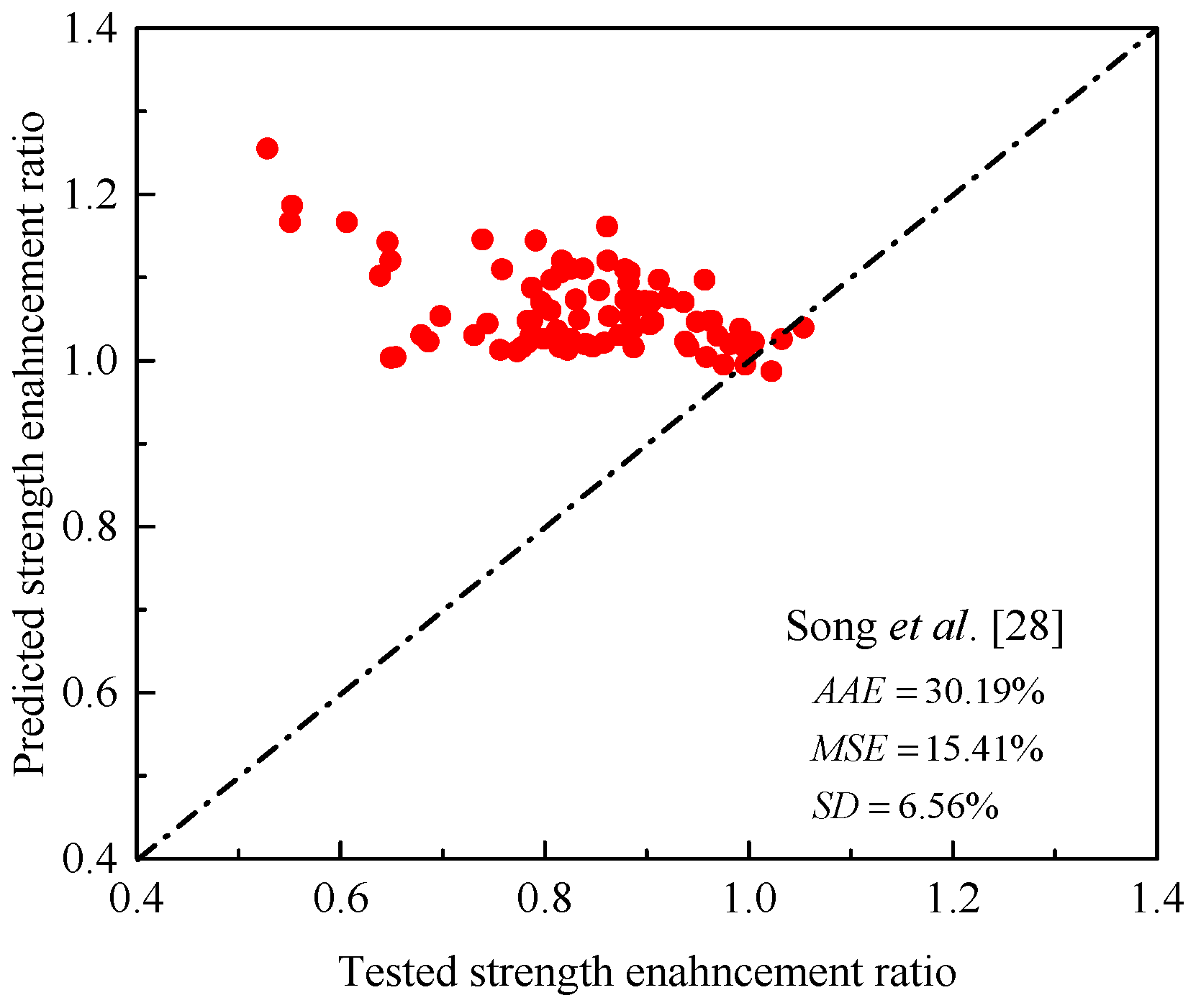
| Song et al. [28] | 254.77 | 304.86 | 1660.88 | 320.99 | - | - | - | - |
| Hany et al. [61] | 231.61 | 268.75 | 1323.07 | 291.81 | - | - | - | - |
| Wang et al. [62] | 207.44 | 252.52 | 1242.84 | 298.45 | ||||
| ACI 440.2R [63] | 212.31 | 239.21 | 1071.48 | 267.50 | - | - | - | - |
| Yang et al. [22] | - | - | - | - | 141.34 | 69.71 | 60.38 | 56.55 |
| Specimen | Tested Peak Load (KN) | Reduction in Strength (Test) (%) | e/h | Proposed γ | Reduction in Strength (Model) (%) |
|---|---|---|---|---|---|
| Jinglong et al. [42] | |||||
| Z-10 | 496 | - | 0.133 | 0.742 | - |
| Z11 | 163 | −67.14 | 0.600 | 0.261 | −64.86 |
| Darby et al. [33] | |||||
| SE2u | 774 | - | 0.100 | 0.799 | - |
| SE3u | 395 | −48.97 | 0.327 | 0.481 | −39.83 |
| SE4u | 184 | −76.23 | 0.720 | 0.199 | −75.08 |
| Saljoughian and Mostofinejad [37] | |||||
| U-30 | 352 | - | 0.226 | 0.603 | - |
| U-60 | 197 | −44.12 | 0.451 | 0.364 | −39.68 |
| U-90 | 119 | −66.31 | 0.677 | 0.219 | −63.61 |
| U-120 | 81 | −77.07 | 0.902 | 0.132 | −78.05 |
| El Maaddawy et al. [19] | |||||
| SN-e1 | 150 | - | 0.460 | 0.357 | - |
| SN-e2 | 105 | −29.89 | 0.600 | 0.261 | −26.93 |
| R2N-e1 | 149 | - | 0.460 | 0.357 | - |
| R2N-e2 | 111 | −25.57 | 0.600 | 0.261 | −26.93 |
| Yang et al. [22] | |||||
| SR | 733 | - | 0.250 | 0.571 | - |
| LR | 402 | −45.19 | 0.500 | 0.326 | −42.89 |
| Specimen | Tested Peak Load (KN) | Reduction in Strength (Test) (%) | e/h | Proposed γ | Reduction in Strength (Model) (%) |
|---|---|---|---|---|---|
| Jinglong et al. [42] | |||||
| Z-3 | 621 | - | 0.133 | 0.659 | - |
| Z-8 | 195 | −68.59 | 0.600 | 0.209 | −68.30 |
| El Maaddawy [29] | |||||
| FW-e1 | 295 | - | 0.300 | 0.417 | - |
| FW-e2 | 205 | −30.51 | 0.432 | 0.302 | −27.55 |
| FW-e3 | 157 | −46.78 | 0.568 | 0.223 | −46.45 |
| FW-e4 | 95 | −67.79 | 0.860 | 0.126 | −69.68 |
| PW-e1 | 275 | - | 0.300 | 0.417 | - |
| PW-e2 | 200 | −27.27 | 0.432 | 0.302 | −27.55 |
| PW-e3 | 150 | −45.45 | 0.568 | 0.223 | −46.45 |
| PW-e4 | 93 | −66.18 | 0.860 | 0.126 | −69.68 |
| Sadeghian et al. [36] | |||||
| S200-L2T | 491 | - | 0.667 | 0.182 | - |
| S300-L2T | 284 | −42.16 | 1 | 0.099 | −45.53 |
| S200-L4T | 600 | - | 0.667 | 0.182 | - |
| S300-L4T | 356 | −40.67 | 1 | 0.099 | −45.53 |
| El Maaddawy et al. [19] | |||||
| SF-e1 | 186 | - | 0.460 | 0.283 | - |
| SF-e2 | 134 | −27.60 | 0.600 | 0.209 | −26.29 |
| Darby et al. [33] | |||||
| SE2 | 812 | - | 0.100 | 0.728 | - |
| SE3 | 464 | −42.86 | 0.327 | 0.389 | −46.43 |
| SE4 | 249 | −69.33 | 0.720 | 0.164 | −77.45 |
| Hadi et al. [18] | |||||
| 1HC25 | 2076 | - | 0.125 | 0.675 | - |
| 1HC50 | 1433 | −30.97 | 0.250 | 0.475 | −29.60 |
| 3HC25 | 2269 | - | 0.125 | 0.675 | - |
| 3HC50 | 1534 | −32.39 | 0.250 | 0.475 | −29.60 |
| Hassan et al. [21] | |||||
| US-G1F | 1640 | - | 0.125 | 0.675 | - |
| UL-G1F | 455 | −72.26 | 0.625 | 0.198 | −70.64 |
| US-G2F | 2005 | - | 0.125 | 0.675 | - |
| UL-G2F | 492 | −75.46 | 0.625 | 0.198 | −70.63 |
| Elsayed et al. [40] | |||||
| C02 | 375 | - | 0.167 | 0.598 | - |
| C06 | 258 | −31.20 | 0.333 | 0.383 | −35.91 |
| C03 | 434 | - | 0.167 | 0.598 | - |
| C07 | 296 | −31.79 | 0.333 | 0.383 | −35.91 |
| Shaikh and Alishahi [34] | |||||
| CR11 | 1229 | - | 0.143 | 0.641 | - |
| CR12 | 1098 | −10.66 | 0.200 | 0.545 | −15 |
| CR13 | 798 | −35.07 | 0.286 | 0.433 | −32.46 |
| CR21 | 1320 | - | 0.143 | 0.641 | - |
| CR22 | 1020 | −22.72 | 0.200 | 0.545 | −15 |
| CR23 | 884 | −33.03 | 0.286 | 0.433 | −32.46 |
| CR31 | 1283 | - | 0.143 | 0.641 | - |
| CR32 | 998 | −22.21 | 0.200 | 0.545 | −15 |
| CR33 | 840 | −34.53 | 0.286 | 0.433 | −32.46 |
| Reference | Specimen Code | Pucu/Pcc (Test) | Pucu/Pcc (Model) |
|---|---|---|---|
| Saljoughian and Mostofinejad [37] | U-60 | 0.86 | 0.83 |
| U-90 | 0.83 | 0.77 | |
| U-120 | 0.76 | 0.69 | |
| Yang et al. [22] | SR | 0.85 | 0.89 |
| LR | 0.85 | 0.84 | |
| Allawi et al. [35] | 12C45 | 0.84 | 0.84 |
| 12C90 | 0.60 | 0.74 | |
| 6C90 | 0.86 | 0.82 | |
| Song et al. [28] | SSR-3-0 | 0.84 | 0.84 |
| SSR-4-0 | 0.84 | 0.77 | |
| SSR-1-0 | 0.85 | 0.84 | |
| SSR-2-0 | 0.84 | 0.87 | |
| Al-Nimry and Neqresh [32] | C35-U-A | 0.82 | 0.88 |
| C35-U-B | 0.90 | 0.88 | |
| C50-U-A | 0.90 | 0.87 | |
| C50-U-B | 0.97 | 0.87 | |
| C50-U-C | 0.86 | 0.88 | |
| C65-U-A | 0.82 | 0.86 | |
| C65-U-B | 0.80 | 0.87 | |
| Average | 0.84 | 0.83 | |
| Specimen Code | Eccentricity Ratio (e/h) | Wrapping System | Peak Load (KN) | Failure Load (KN) | Strength Enhancement at Peak (%) | Strength Enhancement at Failure (%) |
|---|---|---|---|---|---|---|
| Hassan et al. [21] | ||||||
| US-G1F | 0.1250 | FRP hoop | 1640 | 1532 | - | - |
| US-G2F | 0.1250 | FRP hoop | 2005 | 1959 | 22.3 | 27.9 |
| UL-G1F | 0.6250 | Hoop and longitudinal FRP | 455 | 350 | - | - |
| UL-G2F | 0.6250 | Hoop and longitudinal FRP | 492 | 439 | 8.1 | 25.2 |
| Al-Nimry and Neqresh [32] | ||||||
| C50-C | 0.2500 | FRP hoop | 1469 | 1417 | - | - |
| C65-C | 0.3250 | FRP hoop | 1190 | 1033 | −19 | −27.1 |
| C50-LC | 0.2500 | Hoop and longitudinal FRP | 1430 | 1325 | - | - |
| C65-LC | 0.3250 | Hoop and longitudinal FRP | 1239 | 1166 | −13.4 | −11.99 |
Publisher’s Note: MDPI stays neutral with regard to jurisdictional claims in published maps and institutional affiliations. |
© 2021 by the authors. Licensee MDPI, Basel, Switzerland. This article is an open access article distributed under the terms and conditions of the Creative Commons Attribution (CC BY) license (https://creativecommons.org/licenses/by/4.0/).
Share and Cite
Isleem, H.F.; Abid, M.; Alaloul, W.S.; Shah, M.K.; Zeb, S.; Musarat, M.A.; Javed, M.F.; Aslam, F.; Alabduljabbar, H. Axial Compressive Strength Models of Eccentrically-Loaded Rectangular Reinforced Concrete Columns Confined with FRP. Materials 2021, 14, 3498. https://doi.org/10.3390/ma14133498
Isleem HF, Abid M, Alaloul WS, Shah MK, Zeb S, Musarat MA, Javed MF, Aslam F, Alabduljabbar H. Axial Compressive Strength Models of Eccentrically-Loaded Rectangular Reinforced Concrete Columns Confined with FRP. Materials. 2021; 14(13):3498. https://doi.org/10.3390/ma14133498
Chicago/Turabian StyleIsleem, Haytham F., Muhammad Abid, Wesam Salah Alaloul, Muhammad Kamal Shah, Shayan Zeb, Muhammad Ali Musarat, Muhammad Faisal Javed, Fahid Aslam, and Hisham Alabduljabbar. 2021. "Axial Compressive Strength Models of Eccentrically-Loaded Rectangular Reinforced Concrete Columns Confined with FRP" Materials 14, no. 13: 3498. https://doi.org/10.3390/ma14133498
APA StyleIsleem, H. F., Abid, M., Alaloul, W. S., Shah, M. K., Zeb, S., Musarat, M. A., Javed, M. F., Aslam, F., & Alabduljabbar, H. (2021). Axial Compressive Strength Models of Eccentrically-Loaded Rectangular Reinforced Concrete Columns Confined with FRP. Materials, 14(13), 3498. https://doi.org/10.3390/ma14133498