
Transient Confinement of the Quaternary Tetramethylammonium Tetrafluoroborate Salt in Nylon 6,6 Fibres: Structural Developments for High Performance Properties

Abstract

1. Introduction
2. Materials and Methods
2.1. Materials
2.2. Fibre Formation
2.3. Characterization Techniques
2.3.1. Fourier Transforms Infra-Red Spectroscopy (FTIR)
2.3.2. X-ray Diffraction (XRD)
Crystal Size
Crystal Orientation
The Crystal Perfection Index (CPI)
2.3.3. Nuclear Magnetic Resonance (NMR)
2.3.4. Scanning Electron Microscope (SEM)
2.3.5. Mechanical Properties
3. Results and Discussions
3.1. Structural Development of the Salt-Confined Nylon 6,6 Fibres
3.1.1. Fourier Transform Infra-Red Spectroscopy (FTIR)
3.1.2. X-ray Diffraction (XRD)
The Crystal Structure
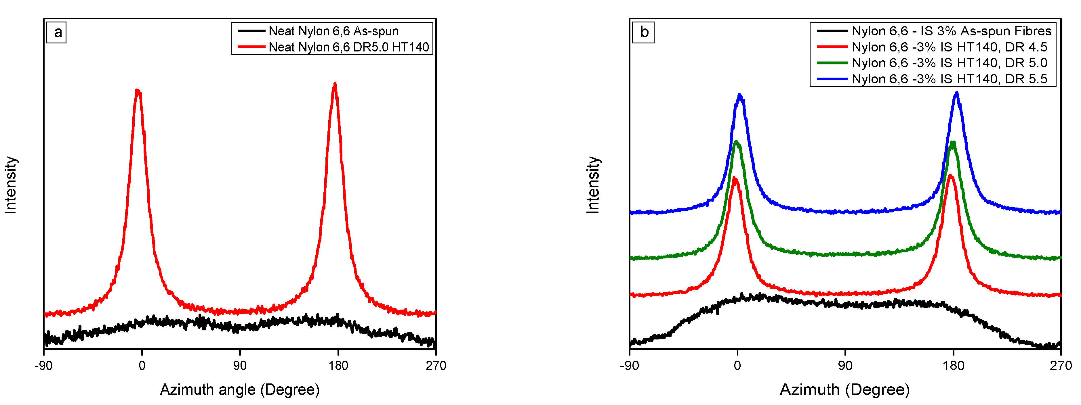
Crystal Orientation
Crystallinity
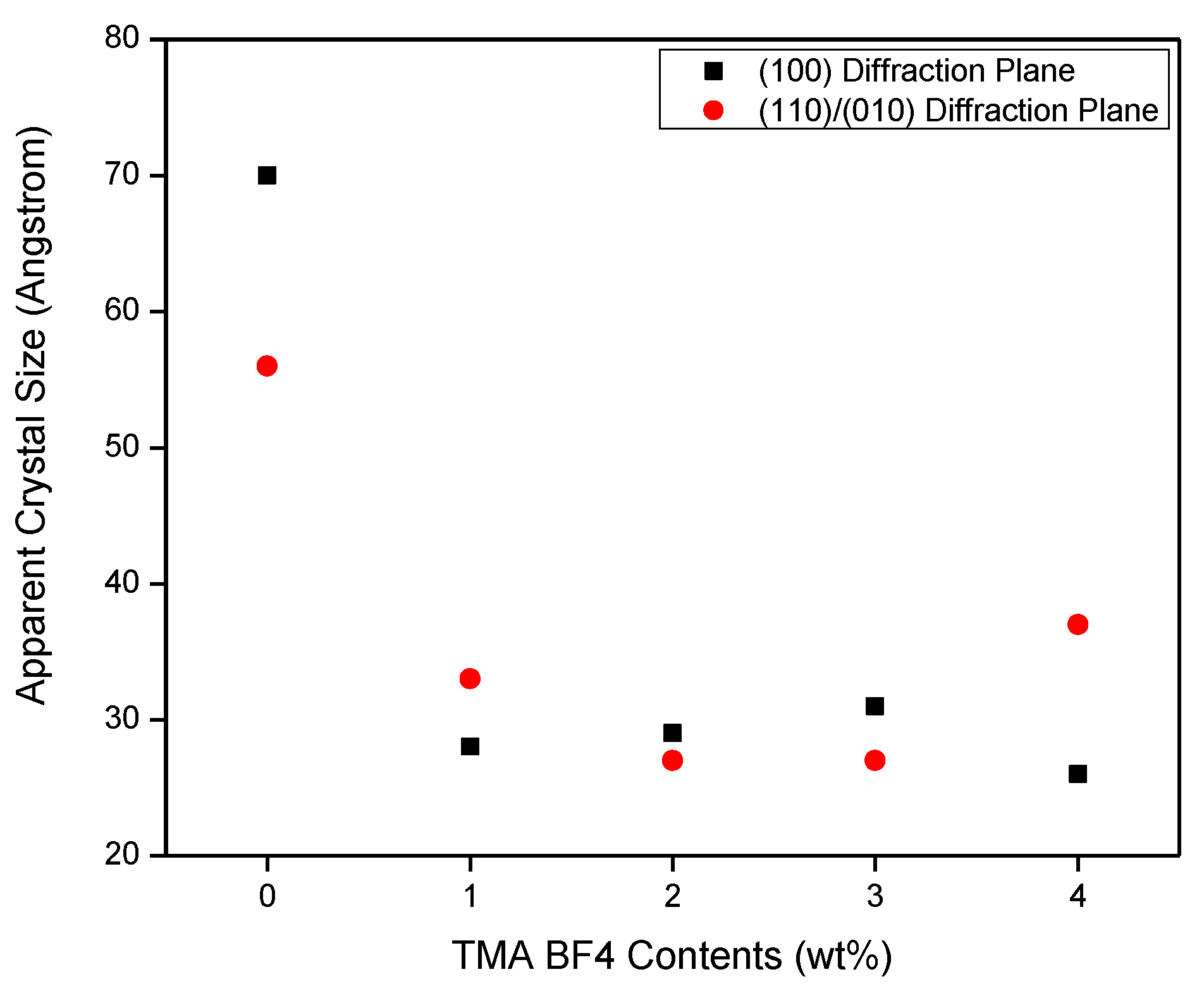
The Apparent Crystal Size (ACS) and The Crystal Perfection Index (CPI)
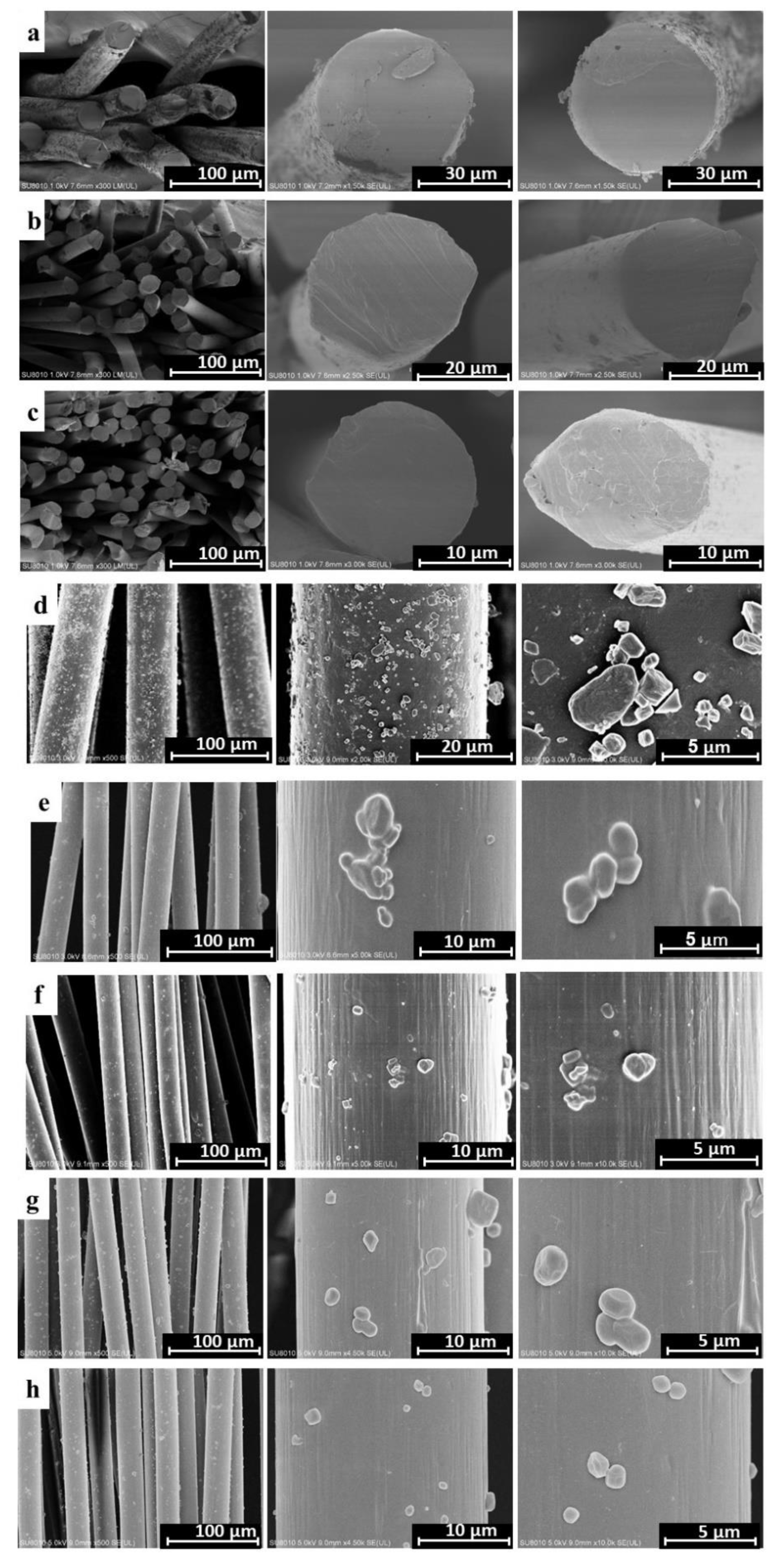
3.1.3. Scanning Electron Microscopy (SEM)
3.2. Mechanical Properties
3.3. The Extraction of the Confined TMA BF4 Salt and the Thermal Stabilization Processes
4. Conclusions
Supplementary Materials
Author Contributions
Funding
Institutional Review Board Statement
Informed Consent Statement
Data Availability Statement
Acknowledgments
Conflicts of Interest
References
- Keller, A. Routes to High Modulus by Ultra-Orientation of Flexible Molecules. In Ultra-High Modulus Polymers; Ciferri, A., Ward, I.M., Eds.; Applied Science Publishers: London, UK, 1979; p. 321. [Google Scholar]
- Yao, J.; Bastiaansen, C.W.M.; Peijs, T. High Strength and High Modulus Electrospun Nanofibers. Fibers 2014, 2, 158–186. [Google Scholar] [CrossRef]
- Ward, I.M. Structure and Properties of Oriented Polymers; Holliday, L., Kelly, A., Eds.; Materials Science Series; Springer Science & Business Media: Ripple Road, Barking, Essex, England, 1975. [Google Scholar]
- Smith, P.; Lemstra, P.J. Ultra-drawing of high molecular weight polyethylene cast from solution. Colloid Polym. Sci. 1980, 258, 891–894. [Google Scholar] [CrossRef]
- Smith, P.; Lemstra, P.J. Ultra-high-strength polyethylene filaments by solution spinning/drawing. J. Mater. Sci. 1980, 15, 505–514. [Google Scholar] [CrossRef]
- Mark, H.; Whitby, G.S. (Eds.) Collected Papers of Wallace Hume Carothers on High Polymeric Substances. In High Polymers; Interscience Publishers, Inc.: New York, NY, USA, 1940; Volume 1. [Google Scholar]
- Carothers, W.H.; Hill, J.W. Studies of polymerization and ring formation. XV. Artificial fibers from synthetic linear condensation superpolymers. J. Am. Chem. Soc. 1932, 54, 1579–1587. [Google Scholar] [CrossRef]
- Lotz, B. Original Crystal Structures of Even–Even Polyamides Made of Pleated and Rippled Sheets. Macromolecules 2021, 54, 551–564. [Google Scholar] [CrossRef]
- Hsiao, B.S.; Kennedy, A.D.; Barton, R., Jr.; Harlow, R.; Ross, R.; Seifert, S.; Zachmann, H.G. In-Situ Structural Characterization During Fiber Melt Spinning Via Synchrotron X-ray Diffraction Measurement. ACS Polym. Prep. 1995, 36, 340–341. [Google Scholar]
- Starkweather, H.W., Jr.; Whitney, J.F.; Johnson, D.R. Crystalline order in nylon 66. J. Polym. Sci. Part A Gen. Pap. 1963, 1, 715–723. [Google Scholar] [CrossRef]
- Ramesh, C.; Keller, A.; Eltink, S. Studies on the crystallization and melting of nylon-6,6: The dependence of the Brill transition on the crystallization temperature. Polymer 1994, 35, 2483–2487. [Google Scholar] [CrossRef]
- Vergelati, C.; Imberty, A.; Perez, S. Water-induced crystalline transition of polyamide 66: A combined x-ray and molecular modeling approach. Macromolecules 1993, 26, 4420–4425. [Google Scholar] [CrossRef]
- Militky, J.; Venkataraman, M.; Mishra, R. The chemistry, manufacture, and tensile behavior of polyamide fibers. In Handbook of Properties of Textile and Technical Fibres, 2nd ed.; Bunsell, A.R., Ed.; Woodhead Publishing Limited: Cambridge, UK, 2018; pp. 367–419. [Google Scholar] [CrossRef]
- Tatsuya, H.; Phillips, G.; Takigami, M. New Millennium Fibers; Woodhead Publishing Limited: Cambridge, UK, 2005. [Google Scholar]
- Lotz, B. Brill Transition in Nylons: The Structural Scenario. Macromolecules 2021, 54, 565–583. [Google Scholar] [CrossRef]
- Danford, M.D.; Spruiell, J.E.; White, J.L. Structure development in the melt spinning of nylon 66 fibers and comparison to nylon. J. Appl. Polym. Sci. 1978, 22, 3351–3361. [Google Scholar] [CrossRef]
- Postema, A.; Smith, P.; English, A.D. Ultra-drawing of polyamide: The hydrogen bond barrier. Polym. Commun. 1990, 31, 444. [Google Scholar]
- Wendoloski, J.J.; Gardner, K.H.; Hirschinger, J.; Miura, H.; English, A.D. Molecular Dynamics in Ordered Structures: Computer Simulation and Experimental Results for Nylon 66 Crystals. Science 1990, 247, 431–436. [Google Scholar] [CrossRef]
- Ward, I.M.; Coated, P.D. Introduction in Solid Phase Processing of Polymers; Ward, I.M., Coated, P.D., Dumoulin, M.M., Eds.; Hanser Publisher: Munich, Germany, 2000. [Google Scholar]
- Mukhopadhyay, S.K. The Structure and Properties of Typical Melt-spun Fibres. Text. Prog. 1988, 18, 1–77. [Google Scholar] [CrossRef]
- Zieminski, K.F.; Spruiell, J.E. On-line studies and computer simulation of the melt spinning of nylon-66 filaments. J. Appl. Polym. Sci. 1988, 35, 2223–2245. [Google Scholar] [CrossRef]
- Shimizu, J. The Fine Structure of Super High Speed Spun Fibers and its Structure Development. Sen’i Gakkaishi 1982, 38, P499–P507. [Google Scholar] [CrossRef]
- Shimizu, J.; Okui, N.; Kikutani, T. Fine Structure and Ohyscal Properties of Fibers Melt-Spun at High Speeds from Various Polymers; Ziabicki, A., Kawai, H., Eds.; John Wiley & Sons: New York, NY, USA, 1985; p. 429. [Google Scholar]
- Hancock, T.A.; Spruiell, J.E.; White, J.L. Wet spinning of aliphatic and aromatic polyamides. J. Appl. Polym. Sci. 1977, 21, 1227–1247. [Google Scholar] [CrossRef]
- Roberts, M.F.; Jenekhe, S.A. Site-specific reversible scission of hydrogen bonds in polymers: An investigation of polyamides and their Lewis acid-base complexes by infrared spectroscopy. Macromolecules 1991, 24, 3142–3146. [Google Scholar] [CrossRef]
- Jenekhe, S.A. Complexation-Mediated Solubilization of Polymers. U.S. Patent 4,963,616, 16 October 1990. [Google Scholar]
- Vasanthan, N.; Kotek, R.; Jung, D.W.; Shin, D.; Tonelli, A.E.; Salem, D.R. Lewis acid–base complexation of polyamide 66 to control hydrogen bonding, extensibility and crystallinity. Polymer 2004, 45, 4077–4085. [Google Scholar] [CrossRef]
- Afshari, M.; Gupta, A.; Jung, D.; Kotek, R.; Tonelli, A.; Vasanthan, N. Properties of films and fibers obtained from Lewis acid–base complexed nylon 6,6. Polymer 2008, 49, 1297–1304. [Google Scholar] [CrossRef]
- Kanamoto, T.; Zachariades, A.E.; Porter, R.S. The effect of anhydrous ammonia on the crystalline-state deformation of nylons 6 and 6,6. J. Polym. Sci. Polym. Phys. Ed. 1982, 20, 1485–1496. [Google Scholar] [CrossRef]
- Salem, D.R. Draw-Induced Structure Development in Flexible-Chain Polymers. In Structure Formation in Polymeric Fibers; Hanser: Munich, Germany, 2000; pp. 118–184. [Google Scholar]
- Murthy, N.S. Structure of iodide ions in iodinated nylon 6 and the evolution of hydrogen bonds between parallel chains in nylon 6. Macromolecules 1987, 20, 309–316. [Google Scholar] [CrossRef]
- Harings, J.A.W.; Deshmukh, Y.S.; Hansen, M.R.; Graf, R.; Rastogi, S. Processing of Polyamides in the Presence of Water via Hydrophobic Hydration and Ionic Interactions. Macromolecules 2012, 45, 5789–5797. [Google Scholar] [CrossRef]
- Suzuki, A.; Murata, H.; Kunugi, T. Application of a high-tension annealing method to nylon 66 fibres. Polymer 1998, 39, 1351–1355. [Google Scholar] [CrossRef]
- Dumbleton, J.H.; Buchanan, D.R. Annealing experiments on drawn nylon 66 fibers. J. Polym. Sci. Part A Polym. Phys. 1968, 6, 1527–1533. [Google Scholar] [CrossRef]
- Dumbleton, J.H.; Buchanan, D.R.; Bowles, B.B. Characterization of nylon 66 structure from x-ray diffraction. J. Appl. Polym. Sci. 1968, 12, 2067–2078. [Google Scholar] [CrossRef]
- Buchanan, D.R.; Dumbleton, J.H. Effect of annealing conditions on the structure of drawn nylon 66 yarns. J. Polym. Sci. Part A Polym. Phys. 1969, 7, 113–122. [Google Scholar] [CrossRef]
- Suzuki, A.; Chen, Y.; Kunugi, T. Application of a continuous zone-drawing method to nylon 66 fibres. Polymer 1998, 39, 5335–5341. [Google Scholar] [CrossRef]
- Zhang, Q.-X.; Yu, Z.-Z.; Yang, M.; Ma, J.; Mai, Y.-W. Multiple melting and crystallization of nylon-66/montmorillonite nanocomposites. J. Polym. Sci. Part B Polym. Phys. 2003, 41, 2861–2869. [Google Scholar] [CrossRef]
- Lin, B.; Thümen, A.; Heim, H.P.; Scheel, G.; Sundararaj, U. Nylon 66/clay nanocomposite structure development in a twin screw extruder. Polym. Eng. Sci. 2009, 49, 824–834. [Google Scholar] [CrossRef]
- Mert, M.; Yilmazer, U. Processing and properties of modified polyamide 66-organoclay nanocomposites. J. Appl. Polym. Sci. 2008, 108, 3890–3900. [Google Scholar] [CrossRef]
- Li, L.; Li, C.Y.; Ni, C.; Rong, L.; Hsiao, B. Structure and crystallization behavior of Nylon 66/multi-walled carbon nanotube nanocomposites at low carbon nanotube contents. Polymer 2007, 48, 3452–3460. [Google Scholar] [CrossRef]
- Meng, Q.-J.; Wang, Z.-M.; Zhang, X.-X.; Wang, X.-C.; Bai, S.-H. Fabrication and Properties of Polyamide-6,6-functionalized Carboxylic Multi-walled Carbon Nanotube Composite Fibers. High Perform. Polym. 2010, 22, 848–862. [Google Scholar] [CrossRef]
- Choi, E.-Y.; Kim, K.; Kim, C.-K.; Kang, E. Reinforcement of nylon 6,6/nylon 6,6 grafted nanodiamond composites by in situ reactive extrusion. Sci. Rep. 2016, 6, 37010. [Google Scholar] [CrossRef] [PubMed]
- Wu, Y.; Xu, Y.; Wang, D.; Zhao, Y.; Weng, S.; Xu, D.; Wu, J. FT-IR spectroscopic investigation on the interaction between nylon 66 and lithium salts. J. Appl. Polym. Sci. 2004, 91, 2869–2875. [Google Scholar] [CrossRef]
- Karacan, I.; Tunçel, K. Şahin Thermal stabilization of poly(hexamethylene adipamide) fibers in the presence of ferric chloride prior to carbonization. Polym. Degrad. Stab. 2013, 98, 1869–1881. [Google Scholar] [CrossRef]
- Prasad, M.; Krishnan, K.; Ninan, K.; Krishnamurthy, V. Thermal decomposition of tetraalkyl ammonium tetrafluoroborates. Thermochim. Acta 1997, 297, 207–210. [Google Scholar] [CrossRef]
- Ue, M. Mobility and Ionic Association of Lithium and Quaternary Ammonium Salts in Propylene Carbonate and γ-Butyrolactone. J. Electrochem. Soc. 1994, 141, 3336–3342. [Google Scholar] [CrossRef]
- Park, S.; Kim, K. Tetramethylammonium tetrafluoroborate: The smallest quaternary ammonium tetrafluoroborate salt for use in electrochemical double layer capacitors. J. Power Sources 2017, 338, 129–135. [Google Scholar] [CrossRef]
- Torre, S.; Ferloni, P. Molecular Motion in Solid Tetramethylammonium Tetrafluoroborate. Z. Nat. A 1992, 47, 721–727. [Google Scholar] [CrossRef]
- Kumiko Sonoda, A.U.; Iwamoto, K. Non-Aqueous Electrolyte and Electrochemical Device Comprising the Same. U.S. Patent US20020028389A1, 7 March 2002. [Google Scholar]
- Zabinska, G.; Ferloni, P.; Sanesi, M. On the thermal behaviour of some tetraalkylammonium tetrafluoroborates. Thermochim. Acta 1987, 122, 87–94. [Google Scholar] [CrossRef]
- Delmerico, S.; McDaniel, J.G. Free energy barriers for TMEA+, TMA+, and BF4- ion diffusion through nanoporous carbon electrodes. Carbon 2020, 161, 550–561. [Google Scholar] [CrossRef]
- Shivanyuk, A. Nanoencapsulation of Calix[4]arene Inclusion Complexes. J. Am. Chem. Soc. 2007, 129, 14196–14199. [Google Scholar] [CrossRef]
- Kvasnica, M.; Purse, B.W. Specific tetramethylammonium recognition drives general anion positioning in tandem sites of a deep cavitand. New J. Chem. 2010, 34, 1097–1099. [Google Scholar] [CrossRef]
- Smith, J.A.; Jaffe, P.R.; Chiou, C.T. Effect of ten quaternary ammonium cations on tetrachloromethane sorption to clay from water. Environ. Sci. Technol. 1990, 24, 1167–1172. [Google Scholar] [CrossRef]
- Colclough, M.L.; Baker, R. Polymorphism in nylon. J. Mater. Sci. 1978, 13, 2531–2540. [Google Scholar] [CrossRef]
- Galimberti, D.; Quarti, C.; Milani, A.; Brambilla, L.; Civalleri, B.; Castiglioni, C. IR spectroscopy of crystalline polymers from ab initio calculations: Nylon 6,6. Vib. Spectrosc. 2013, 66, 83–92. [Google Scholar] [CrossRef]
- Vasanthan, N.; Salem, D.R. Infrared spectroscopic characterization of oriented polyamide 66: Band assignment and crystallinity measurement. J. Polym. Sci. Part B Polym. Phys. 2000, 38, 516–524. [Google Scholar] [CrossRef]
- Vasanthan, N.; Ruetsch, S.B.; Salem, D.R. Structure development of polyamide-66 fibers during drawing and their microstructure characterization. J. Polym. Sci. Part B Polym. Phys. 2002, 40, 1940–1948. [Google Scholar] [CrossRef]
- Palacios, E.; Melero, J.J.; Burriel, R.; Ferloni, P. Structural, calorimetric, and Monte Carlo investigation of the order-disorder transition of BF4 in (CH 3)4NBF4. Phys. Rev. B 1996, 54, 9099–9108. [Google Scholar] [CrossRef]
- Shodai, Y.; Kohara, S.; Ohishi, Y.; Inaba, M.; Tasaka, A. Anionic Species (FH)xF- in Room-Temperature Molten Fluorides (CH3)4NF·mHF. J. Phys. Chem. A 2004, 108, 1127–1132. [Google Scholar] [CrossRef]
- Parravicini, G.; Marabelli, F.; Floris, F.M.; Pasquali, V.; Parravicini, J.; Ferloni, P. Thermal evolution of tetramethylammonium tetrafluoborate and perchlorate investigated through dielectric and IR spectroscopy. Mater. Chem. Phys. 2014, 147, 120–126. [Google Scholar] [CrossRef]
- Koller, J.; Grdadolnik, J.; Hadzi, D. Tetramethylammonium as proton donor in hydrogen bonding: An ab initio and infrared study. J. Mol. Struct. Theochem. 1992, 259, 199–209. [Google Scholar] [CrossRef]
- Cannon, C. The infra-red spectra and molecular configurations of polyamides. Spectrochim. Acta 1960, 16, 302–319. [Google Scholar] [CrossRef]
- Kang, E.; Kim, M.; Oh, J.S.; Park, D.W.; Shim, S.E. Electrospun BMIMPF6/nylon 6,6 nanofiber chemiresistors as organic vapour sensors. Macromol. Res. 2012, 20, 372–378. [Google Scholar] [CrossRef]
- Bunn, C.W.; Garner, E.V. The Crystal Structures of Two Polyamides (‘Nylons’). Proc. R. Soc. Lond. Ser. A Math. Phys. Sci. 1947, 189, 39–68. [Google Scholar]
- Holmes, D.R.; Bunn, C.W.; Smith, D.J. The crystal structure of polycaproamide: Nylon 6. J. Polym. Sci. 1955, 17, 159–177. [Google Scholar] [CrossRef]
- Matsumoto, K.; Harinaga, U.; Tanaka, R.; Koyama, A.; Hagiwara, R.; Tsunashima, K. The structural classification of the highly disordered crystal phases of [Nn][BF4], [Nn][PF6], [Pn][BF4], and [Pn][PF6] salts (Nn+ = tetraalkylammonium and Pn+ = tetraalkylphosphonium). Phys. Chem. Chem. Phys. 2014, 16, 23616–23626. [Google Scholar] [CrossRef]
- Hsiao, B.S.; Kennedy, A.D.; Leach, R.A.; Chu, B.; Harney, P. Studies of Structure and Morphology Development During the Heat-Draw Process of Nylon 66 Fiber by Synchrotron X-ray Diffraction and Scattering Techniques. J. Appl. Crystallogr. 1997, 30, 1084–1095. [Google Scholar] [CrossRef]
- Ran, S.; Cruz, S.; Zong, X.; Fang, D.; Chu, B.; Hsiao, B.S.; Ross, R.; Chang, H.; Londono, D. Structure Development during the Heat-Draw Process of Nylon 66 Fiber by Synchrotron X-ray Diffraction. Adv. X-ray Anal. 2000, 43, 313–318. [Google Scholar]
- Keller, A. Crystal configurations and their relevance to the crystalline texture and crystallization mechanism in polymers. Kolloid Z. Z. Polym. 1964, 197, 98–115. [Google Scholar] [CrossRef]
- Choy, C.L.; Leung, W.P.; Ong, E.L.; Wang, Y. Mechanical anisotropy in rolled nylon. J. Polym. Sci. Part B Polym. Phys. 1988, 26, 1569–1584. [Google Scholar] [CrossRef]
- Ziabicki, A. Fundamentals of Fibre Formation; A Wiley-Interscience Publication: New York, NY, USA, 1976. [Google Scholar]


| Sample | Crystallinity (%) | Interplanar Space (d-Spacing), Å | Crystal Perfection, CPI (%) | Apparent Crystal Size, ACS (Å) | Orientation Angle (Degree) | ||||
|---|---|---|---|---|---|---|---|---|---|
| (100) | (010) | (100) | (010) | ||||||
| Neat nylon 6,6, as-spun fibres | 38.24 | 4.3671 | 3.8541 | 70.426 | 70 | 56 | 0.238 | −0.144 | 60.84 |
| Nylon 6,6-1% IS as-spun fibre | 58.60 | 4.3247 | 3.8473 | 65.655 | 28 | 33 | 0.625 | 0.438 | 37.76 |
| Nylon 6,6-2% IS as-spun fibre | 64.76 | 4.3344 | 3.8418 | 67.842 | 29 | 27 | 0.653 | 0.480 | 36.10 |
| Nylon 6,6-3% IS as-spun fibre | 63.33 | 4.3184 | 3.8419 | 65.623 | 31 | 27 | 0.460 | 0.191 | 47.27 |
| Nylon 6,6-4% IS as-spun fibre | 59.23 | 4.3195 | 3.8048 | 71.575 | 26 | 37 | 0.618 | 0.428 | 38.16 |
| Samples | Crystallinity (%) | Interplanar Space (d-Spacing), Å | Crystal Perfection, CPI (%) | Apparent Crystal Size, ACS (Å) | Orientation Angle (Degree) | ||||
|---|---|---|---|---|---|---|---|---|---|
| (100) | (010) | (100) | (010) | ||||||
| Nylon 6,6-3% IS as-spun fibre | 63.33 | 4.3184 | 3.8419 | 65.623 | 31 | 27 | 0.460 | 0.191 | 47.27 |
| Nylon 6,6-3% IS DR 4.5 HT120 | 71.24 | 4.3243 | 3.8142 | 70.760 | 31 | 29 | 0.741 | 0.612 | 30.57 |
| Nylon 6,6-3% IS DR 5.0 HT120 | 69.17 | 4.3297 | 3.8028 | 73.31 | 32 | 28 | 0.868 | 0.803 | 21.28 |
| Nylon 6,6-3% IS DR 5.5 HT120 | 72.58 | 4.3489 | 3.8266 | 72.218 | 35 | 29 | 0.760 | 0.640 | 29.34 |
| Nylon 6,6-3% IS DR 4.5 HT140 | 58.36 | 4.3520 | 3.8549 | 68.23 | 47 | 33 | 0.843 | 0.764 | 23.35 |
| Nylon 6,6-3% IS DR 5.0 HT140 | 50.09 | 4.3444 | 3.8627 | 65.98 | 44 | 31 | 0.790 | 0.686 | 27.24 |
| Nylon 6,6-3% IS DR 5.5 HT140 | 58.02 | 4.3713 | 3.8455 | 72.35 | 44 | 30 | 0.928 | 0.892 | 15.55 |
| Nylon 6,6-3% IS DR 4.5 HT160 | 50.39 | 4.3405 | 3.8537 | 66.84 | 41 | 32 | 0.825 | 0.738 | 24.70 |
| Nylon 6,6-3% IS DR 5.0 HT160 | 52.64 | 4.3460 | 3.8527 | 67.75 | 42 | 29 | 0.935 | 0.903 | 14.76 |
| Nylon 6,6-3% IS DR 5.5 HT160 | 54.86 | 4.3516 | 3.8577 | 67.74 | 49 | 27 | 0.886 | 0.829 | 19.72 |
| Drawing Temperature (°C) | Neat Nylon 6,6 Fibres | Salt-Confined Nylon 6,6 Fibres | ||||||
|---|---|---|---|---|---|---|---|---|
| Draw Ratio | Tensile Modulus (cN/dtex) | Tensile Strength (cN/dtex) | Elongation(%) | Draw Ratio | Tensile Modulus (cN/dtex) | Tensile Strength (cN/dtex) | Elongation(%) | |
| 120 | 4.0 | 13.3 | 2.9 | 70.9 | 4.5 | 19.9 | 3.1 | 15.6 |
| 120 | 4.5 | 13.7 | 3.1 | 67.5 | 5.0 | 26.5 | 3.7 | 14.0 |
| 120 | 5.0 | 23.3 | 4.1 | 29.6 | 5.5 | 32.8 | 5.0 | 15.1 |
| 140 | 4.0 | 13.2 | 3.1 | 78.8 | 4.5 | 20.8 | 2.8 | 13.6 |
| 140 | 4.5 | 16.9 | 3.3 | 47.0 | 5.0 | 31.8 | 4.1 | 12.8 |
| 140 | 5.0 | 21.8 | 3.9 | 33.7 | 5.5 | 35.8 | 4.2 | 11.6 |
| 160 | 4.5 | 16.5 | 3.7 | 67.7 | 4.5 | 27.3 | 3.1 | 11.1 |
| 160 | 5.0 | 20.8 | 4.0 | 41.4 | 5.0 | 31.0 | 3.7 | 11.9 |
| 160 | 5.5 | 26.3 | 4.7 | 30.7 | 5.5 | 33.4 | 4.5 | 13.5 |
| Fibre Type * | Drawing Temperature (°C) | Tension (Gram Force) | Tensile Modulus (cN/dtex) | Tensile Strength (cN/dtex) | Elongation (%) |
|---|---|---|---|---|---|
| Regenerated Nylon 6,6 Fibres -1# | RT | - | 35.62 | 6.31 | 26.57 |
| Stabilized Nylon 6,6 Fibres 1-1 | 190 | 98 cN | 39.94 | 6.81 | 26.07 |
| Stabilized Nylon 6,6 Fibres 1-2 | 190 | 196 cN | 43.32 | 6.99 | 25.06 |
| Regenerated Nylon 6,6 Fibres -2# | RT | - | 39.81 | 6.48 | 31.70 |
| Stabilized Nylon 6,6 Fibres 2-1 | 190 | 98 cN | 33.44 | 6.55 | 29.23 |
| Stabilized Nylon 6,6 Fibres 2-2 | 190 | 196 cN | 35.96 | 6.94 | 29.20 |
Publisher’s Note: MDPI stays neutral with regard to jurisdictional claims in published maps and institutional affiliations. |
© 2021 by the authors. Licensee MDPI, Basel, Switzerland. This article is an open access article distributed under the terms and conditions of the Creative Commons Attribution (CC BY) license (https://creativecommons.org/licenses/by/4.0/).
Share and Cite
Dawelbeit, A.; Yu, M. Transient Confinement of the Quaternary Tetramethylammonium Tetrafluoroborate Salt in Nylon 6,6 Fibres: Structural Developments for High Performance Properties. Materials 2021, 14, 2938. https://doi.org/10.3390/ma14112938
Dawelbeit A, Yu M. Transient Confinement of the Quaternary Tetramethylammonium Tetrafluoroborate Salt in Nylon 6,6 Fibres: Structural Developments for High Performance Properties. Materials. 2021; 14(11):2938. https://doi.org/10.3390/ma14112938
Chicago/Turabian StyleDawelbeit, Ahmed, and Muhuo Yu. 2021. "Transient Confinement of the Quaternary Tetramethylammonium Tetrafluoroborate Salt in Nylon 6,6 Fibres: Structural Developments for High Performance Properties" Materials 14, no. 11: 2938. https://doi.org/10.3390/ma14112938
APA StyleDawelbeit, A., & Yu, M. (2021). Transient Confinement of the Quaternary Tetramethylammonium Tetrafluoroborate Salt in Nylon 6,6 Fibres: Structural Developments for High Performance Properties. Materials, 14(11), 2938. https://doi.org/10.3390/ma14112938