Effect of Internal Support on the Tensile Properties and Fracture Mode of 304 Stainless Steel Thin-Walled Tubes


Abstract
1. Introduction
2. Materials and Methods
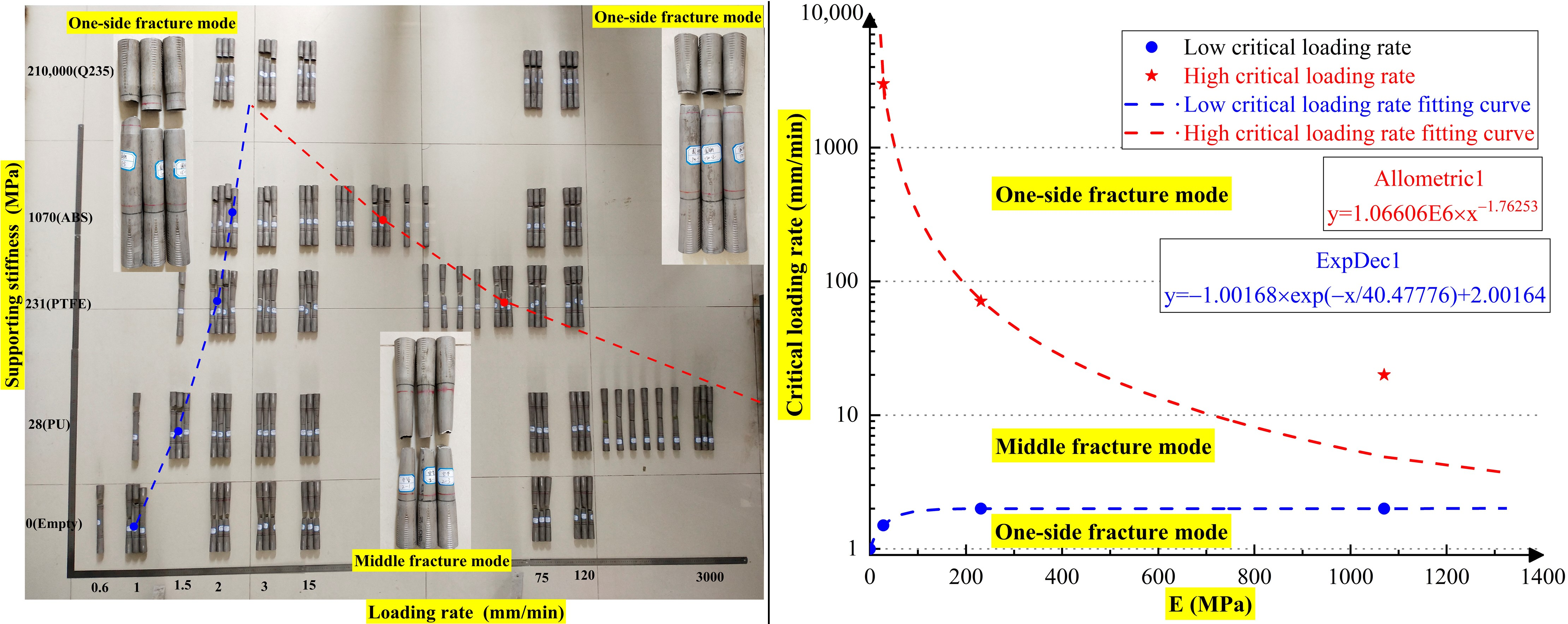
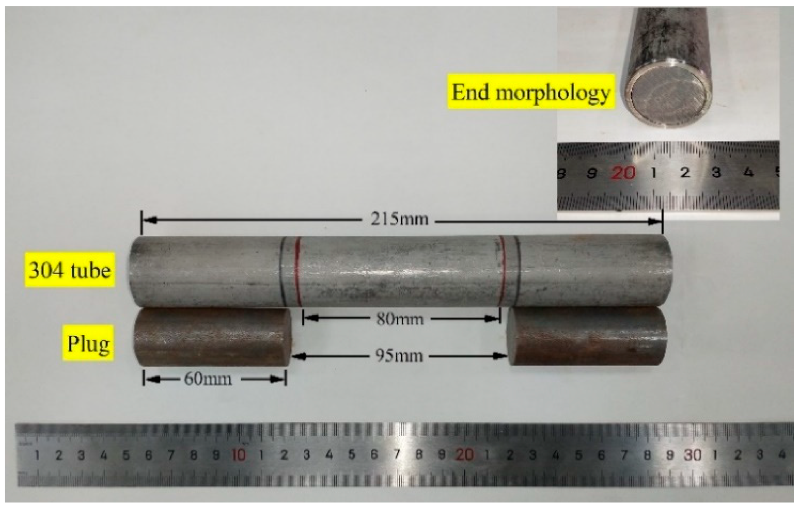
2.1. Sample Preparation
2.2. Loading Method
- (a)
- Loading equipment: Under the condition of a loading rate below 120 mm/min, the Shenzhen Wance 100-ton HUT106D microcomputer-controlled electrohydraulic servo universal testing machine (vmax = 120 mm/min, located at the Army Engineering University of PLA in Nanjing, China) was used. For loading rates above 120 mm/min, the w+b servohydraulic dynamic fatigue testing system (vmax = 3000 mm/min, located at Southeast University in Nanjing, China) was employed.
- (b)
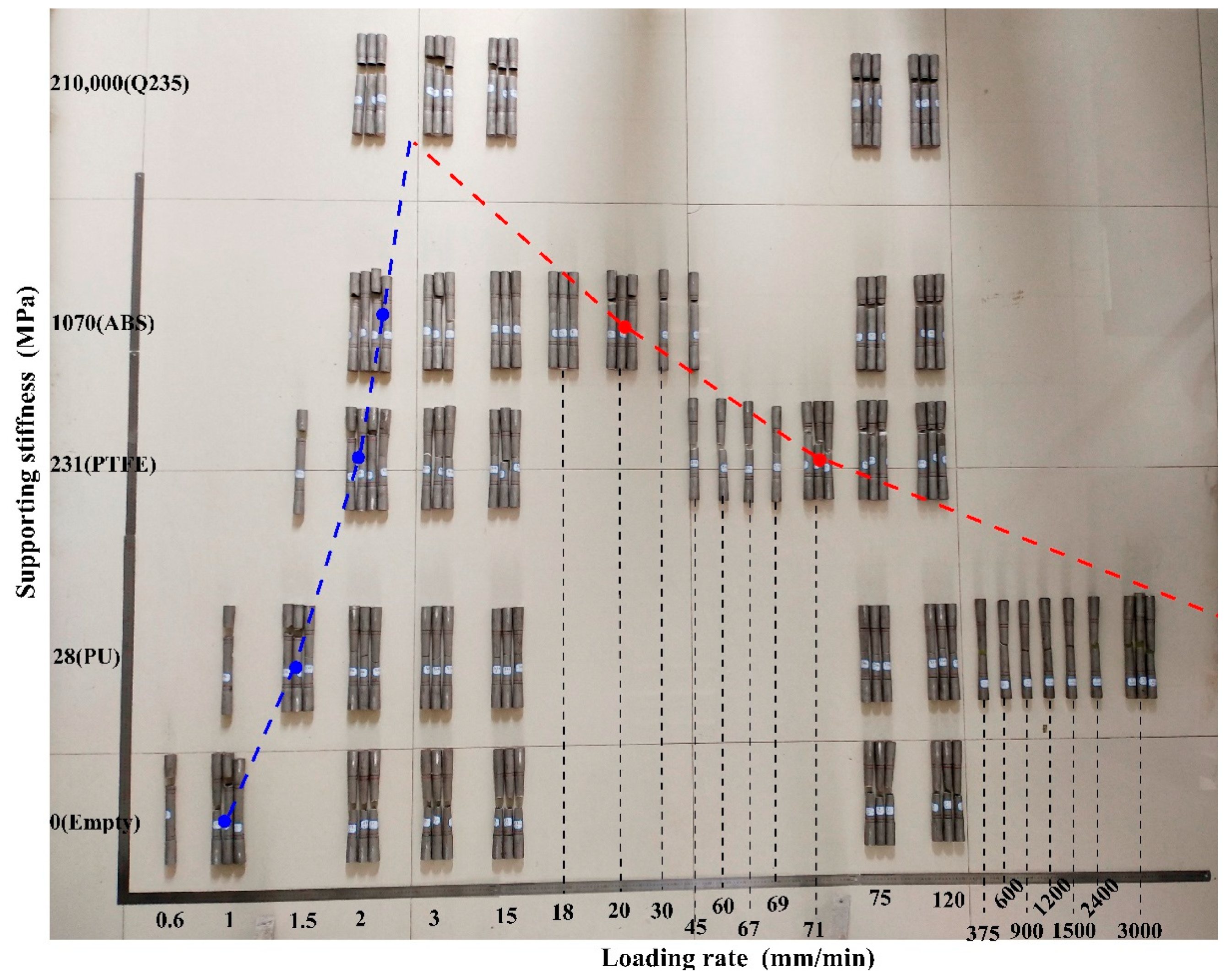
- Loading rate: Five levels of loading rates were set: 2, 3, 15, 75, and 120 mm/min. The fracture matrix of the specimen was obtained based on these five support conditions. To explore the critical loading rate for the switching of fracture mode under different support conditions, a loading rate within the range of 0.6–3000 mm/min was set for some specimens. A quasistatic strain rate in the order of 1.05 × 10⁻⁴−5.26 × 10⁻¹ s−1 was achieved.
- (c)
- Sampling frequency: When the loading rate was below 120 mm/min, the sampling frequency was 10 Hz. When the loading rate was above 120 mm/min, the sampling frequency was 200 Hz.
2.3. Testing Procedure
- (a)
- Calibration of the testing machine: Through a series of elastic tensile tests on the circular steel specimens, it was found that the inherent displacement and the tensile force of the testing machine exhibited a good linear relation, which satisfied repeatability. During data processing, the displacement of the testing machine caused by the tensile force was deducted. After the above calibration process, the displacement value became closer to the true extension of the specimen.
- (b)
- The specimens and fixtures were cleaned and degreased before stretching to prevent them from slipping off during the stretching process.
- (c)
- The specimen was installed and then stretched until it broke according to the set loading rate.
- (d)
- The test data were recorded and then processed using the Origin data processing software.
3. Results and Analysis
3.1. Effect of Internal Support on the Fracture Mode of 304 SSTWTs
3.2. Failure Test Results of Standard Specimens of 304 SSTWTs
3.3. Effect of Internal Support on the Mechanical Properties of 304 SSTWTs
- (a)
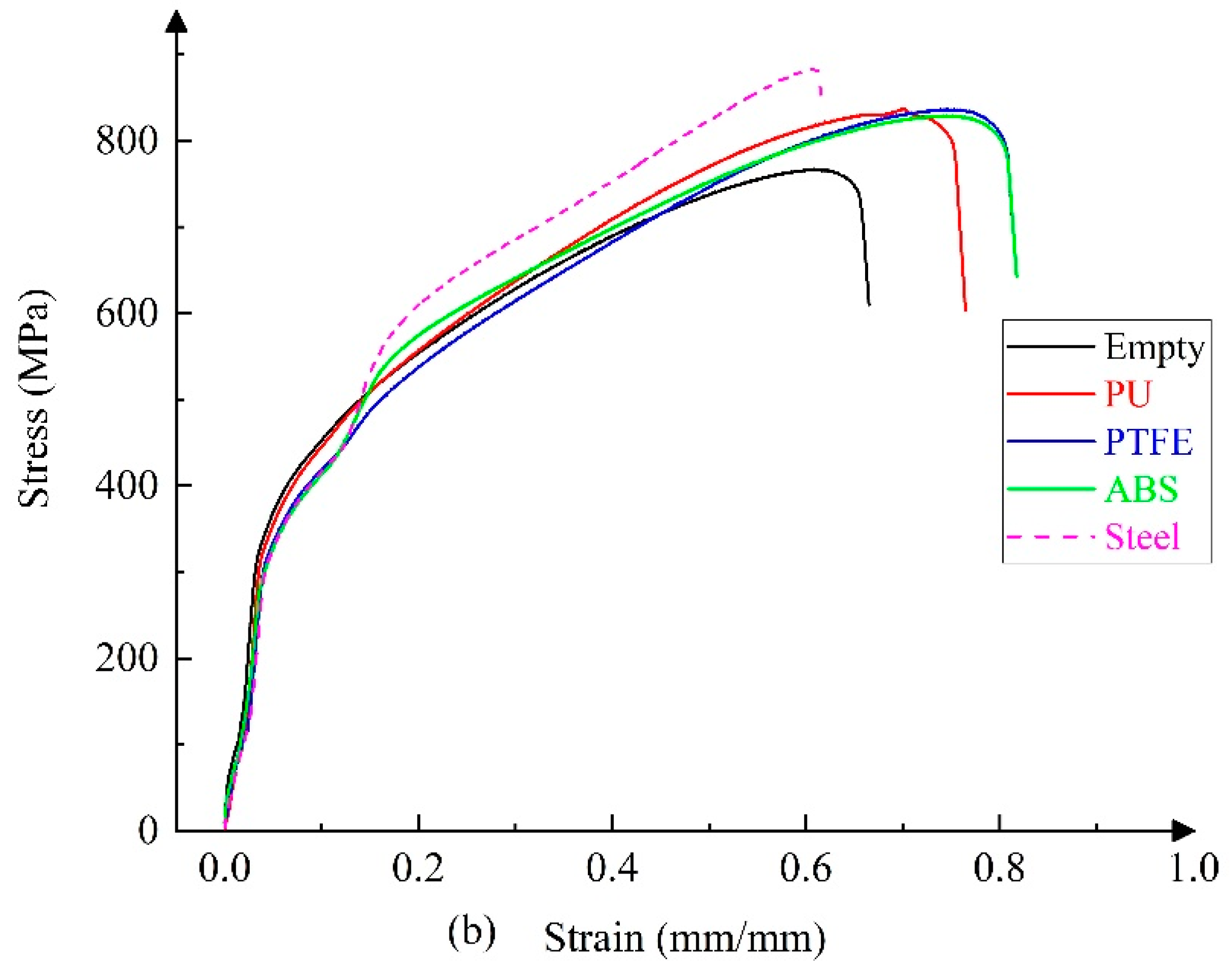
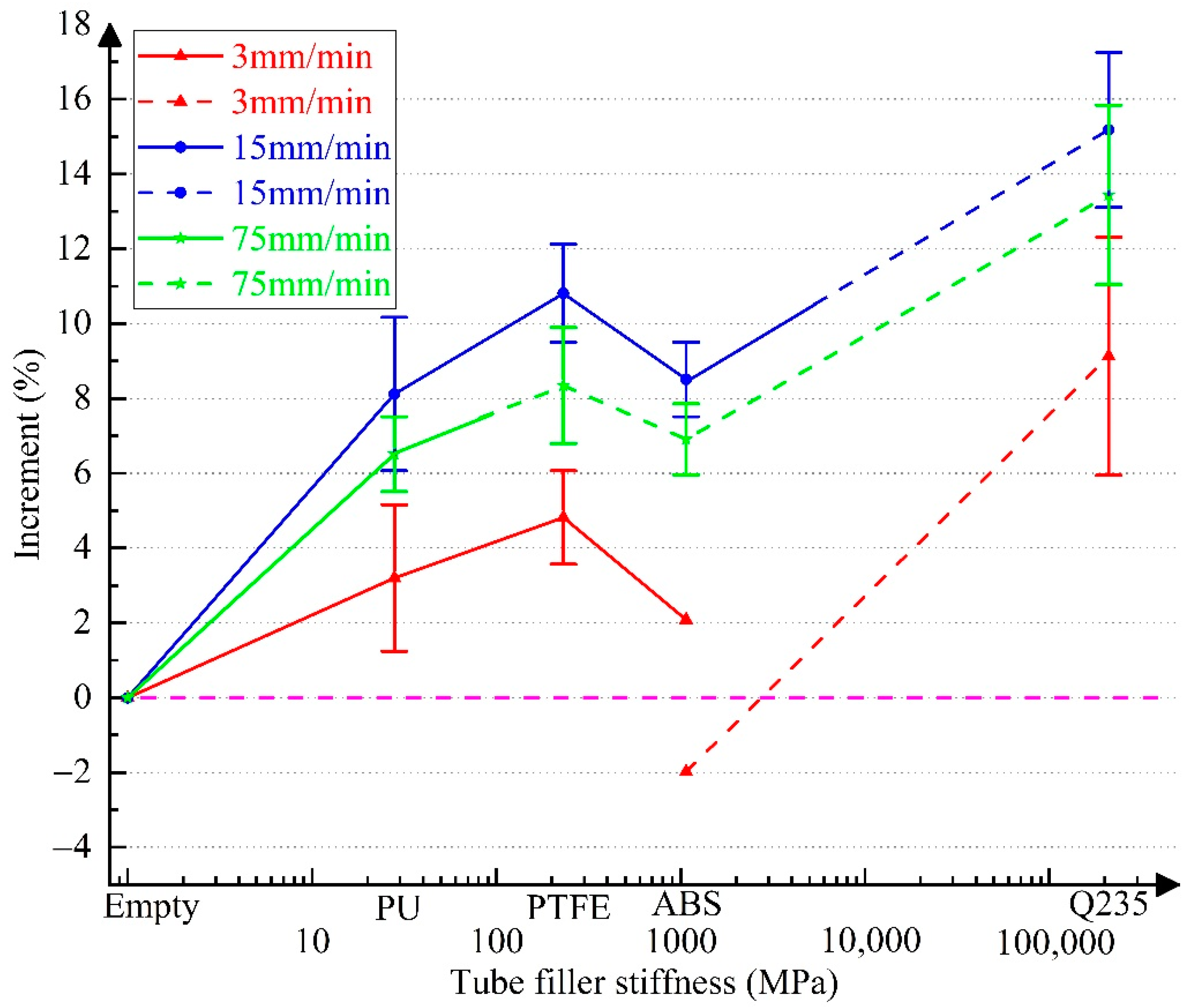
- As the tube filler stiffness increases, the ultimate strength initially increases and then decreases. After the fracture mode switches, the ultimate strength is still higher than that of the empty tube.
- (b)
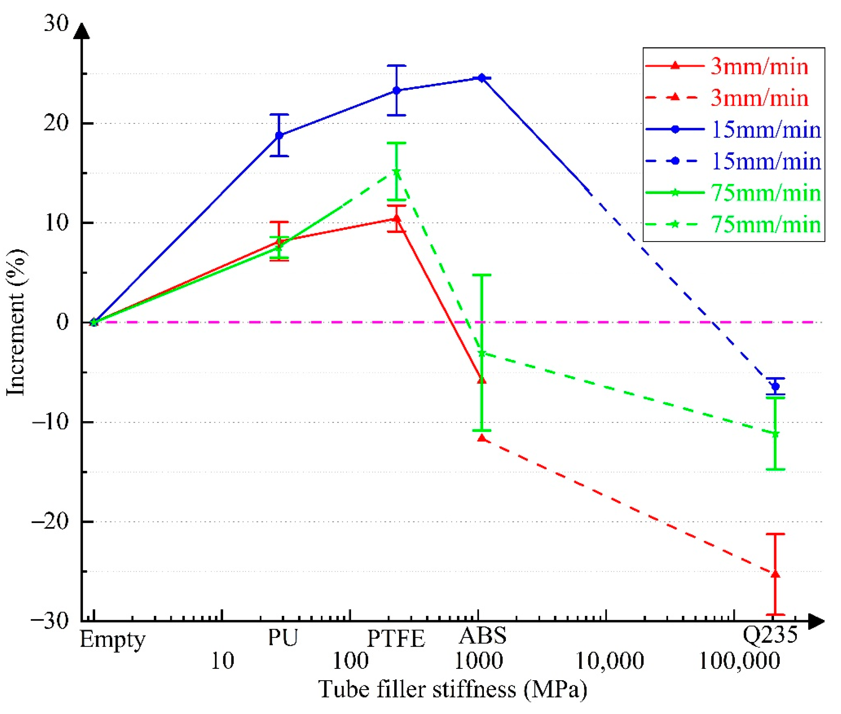
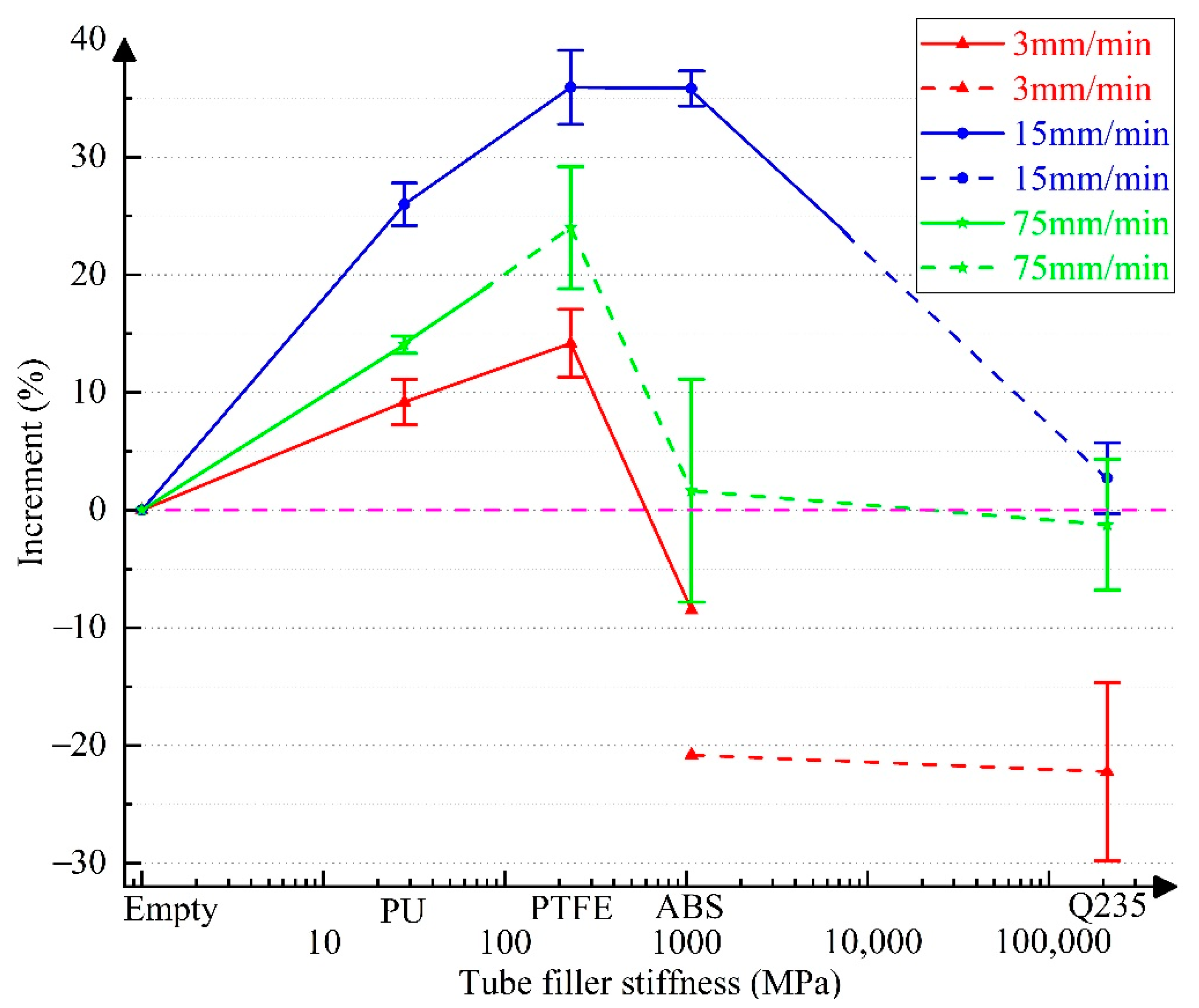
- As the tube filler stiffness increases, both extension and fracture energy increase first and then decrease.
- (c)
- When the tube filler stiffness reaches ~500–1000 MPa, the tube extension begins to demonstrate a negative increment. As the tube filler stiffness further increases, the decreasing trend becomes more obvious. Therefore, the rising trend of fracture energy is also reversed.
- (d)
- When the loading rate is 15 mm/min, the increment in the mechanical properties of the tube becomes maximum. In the middle fracture mode of the tube section, the ultimate strength, extension, and fracture energy exhibit a maximum increment of 10.81% (PTFE), 24.56% (ABS), and 35.94%. (PTFE), respectively.
- (a)
- ABS and PTFE cause the most significant improvement in the mechanical performance of 304 SSTWTs at the ideal loading rate (15 mm/min). The increment in the fracture energy exceeds 35%. Tubular specimens filled with PU under the same loading rate have a slightly inferior performance, where the fracture energy increases by 26.01%.
- (b)
- From the perspective of the applicability of loading rates, when the supporting material is ABS and PTFE with a larger elastic modulus, the tube is prone to fracture on the clamping side under higher and lower loading rates. This causes relatively large uncertainty in the mechanical properties of tubular specimens. When the supporting material is PU with a smaller elastic modulus, the tube tends to fracture on the clamping side only under extremely low loading rate conditions.
- (c)
- It is noteworthy that PTFE has a large density and high cost. ABS has the smallest density, but it is expensive. PU has a lower density, which is only ½ of the PTFE density, and the unit volume price is about 1/3 of that of PTFE and ABS. In addition, PU exhibits strong deformability with a wide elastic range. Thus, it does not break due to excessive deformation and can maintain the integrity of failed tubular specimens.
4. Mechanism of Enhancement Effect of Internal Support
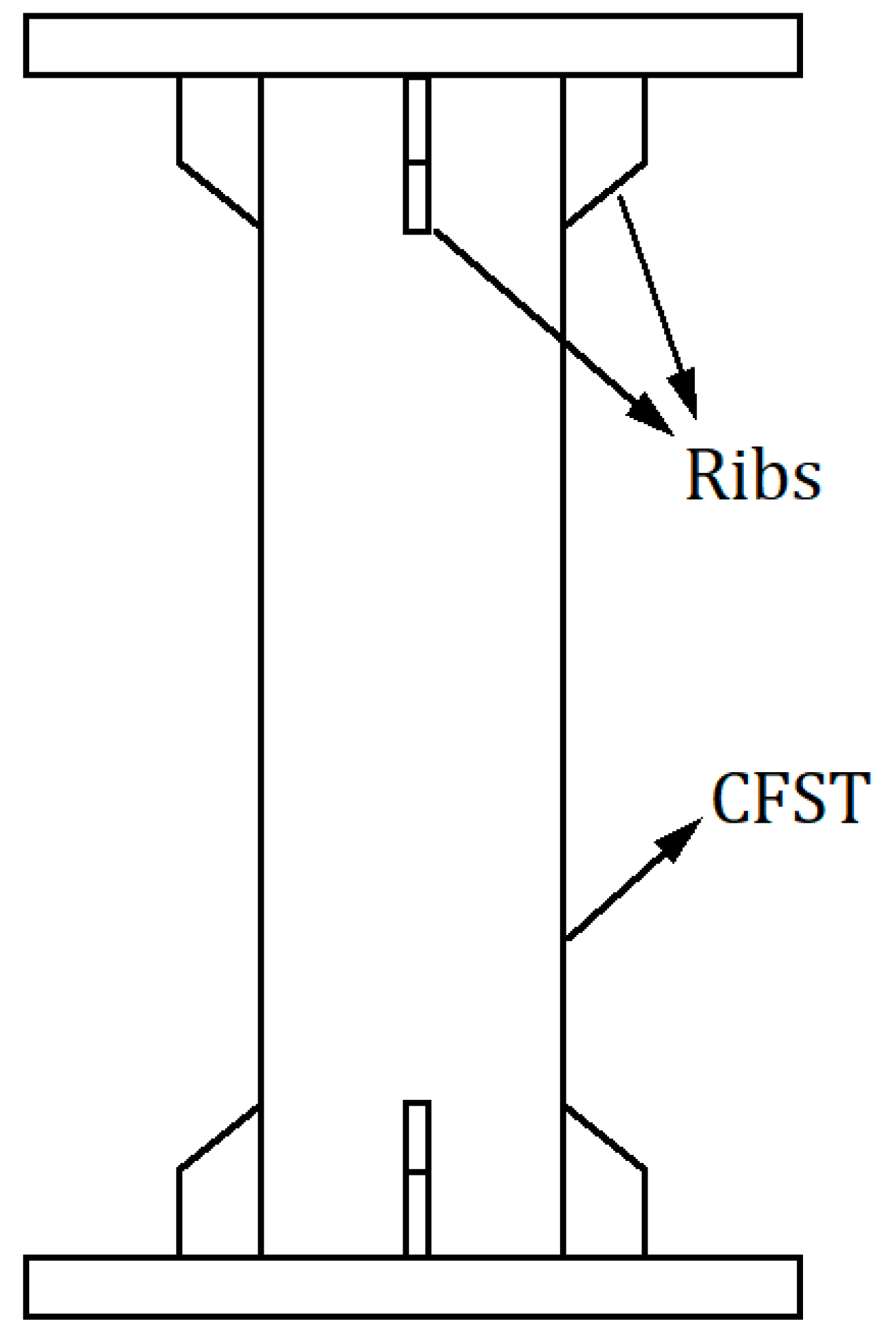
4.1. Stress State Analysis of the CFST Specimen
4.2. Stress States of 304 SSTWTs under Different Internal Supports
4.3. Working Mechanism
- (a)
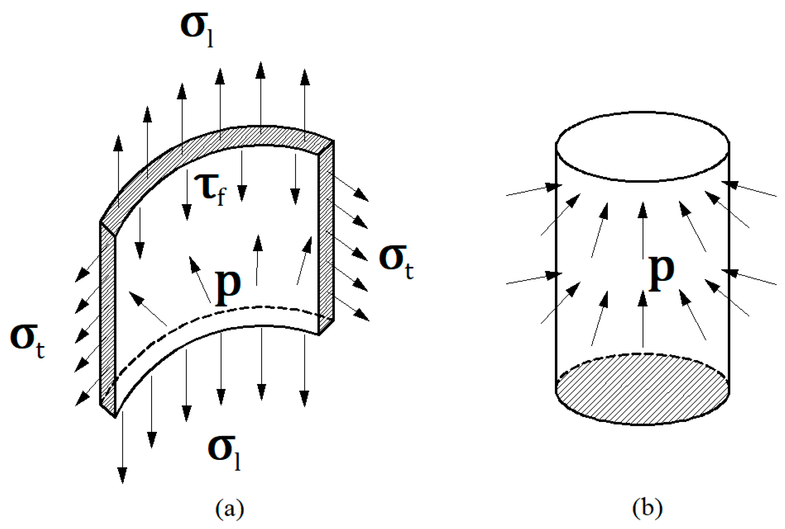
- Since is much smaller than , , and p, the longitudinal shear stress in the middle of the tube section is ignored.
- (b)
- is constant in the thickness direction, so and p satisfy the following relation: . Substituting the specimen size in this test yields (assuming that does not change during the stretching process). With internal support, the stress state of a 304 SSTWT in the middle of the tube section is shown in Figure 13.
- (c)
- The second invariant of the deviator stress under the fracture of a 304 SSTWT is constant.
- (a)
- When , as p increases, the maximum increment of reaches 8.5%, i.e., when the elastic modulus of tube filler is less than a certain critical value, rises with the increase in E.
- (b)
- A large value of tube filler stiffness is not always favorable. When the tube filler stiffness becomes greater than a certain critical value (i.e., when p exceeds the critical value), as E increases, exhibits a decreasing trend. This also explains the observations in Figure 7, i.e., why the elastic modulus of ABS is greater than that of PTFE, whereas the improvement in ultimate tensile strength by ABS is less than that by FTFE.
5. Discussion
5.1. Comparative Analysis of the Effect of Internal Support on the Mechanical Properties of Tubes
- (a)
- According to the tensile properties of tubular specimens in Refs. [32,33,34,35,36,37] (Ref. [38] proposed a double-layer CFST sandwich structure, which is different from Refs. [32,33,34,35,36,37]), the filling of concrete in a hollow steel tube can increase the ultimate bearing capacity by 5–11%. The present results indicate that the filling of PU can improve the ultimate bearing capacity of tubes by 2.85–8.12%. Basically, the flexible support can provide the equivalent improvement as a rigid support.
- (b)
- The typical PU flexible support can significantly improve the ultimate deformability of tubular specimens while increasing the ultimate bearing capacity. At a loading rate of 15 mm/min, the tube extension can be increased by 1.73–18.78% if PU is used as the filling material. The variation in the extension rate of CFST has not been clarified in the existing literature. However, from the perspective of the fracture mode of a rigid support (Q235 circular steel) specimen, if the end is not reinforced, the tube is prone to fracture on the clamping side. Therefore, the extension rate is significantly reduced, which is not conducive to the safety of components and structures.
- (c)
- When PU is used as the filling material, the fracture energy of tubes can be increased by 5.55–26.01%. When a rigid support (Q235 circular steel) is used, the increment in the fracture energy of tubes is −22.23–2.73%. The increase in the ultimate bearing capacity can barely compensate for the adverse effect on the extension rate at the optimal loading rate (under 15 mm/min). In most cases, the fracture energy is considerably reduced. Generally, the elastic modulus of concrete is 25–40 GPa, and the deformability is weak. Its effect is close to that of the rigid support, i.e., it has a negative effect on the toughness of tubular specimens.
- (d)
- From the perspective of weight, the density of PU is less than half of the concrete density, which is more conducive for the lightweight design of structures. In terms of construction technology, the use of PU for filling is convenient and does not require maintenance, and it is also suitable for assembled steel–tube composite structures. On the contrary, a CFST structure requires a longer maintenance period, complicated processing and manufacturing, stricter requirements for site and equipment, and higher overall cost.
5.2. Comparative Analysis of the Effect of Internal Support on the Fracture Mode of Tubes
5.3. Application and Future Directions
- (a)
- In this experiment, only one type of 304 stainless steel tube was tested, and the effects of tube material, length–diameter ratio, and –diameter ratio on the effect of internal support were not considered.
- (b)
- This test focuses on the impact of internal support on the tensile properties and fracture mode of tubes. The improvement in the mechanical properties of tubes under complex stress conditions such as bending, tension, torsion, and impacts needs to be further investigated.
- (c)
- Through the comparison of four supporting materials, it is concluded that PU has the best overall performance, but it is relatively expensive. Finding inexpensive tube fillers with a suitable elastic modulus, further reducing the manufacturing cost and structural weight, and the industrialization of internal support structures are worth exploring.
6. Conclusions
- (1)
- Due to the supporting effect of internal filling materials, the lateral necking of circular tubes toward the axis of symmetry during stretching was restricted. The ultimate tensile bearing capacity, extension, and fracture energy of the specimens were significantly increased. The flexible tube filler and the thin-walled tension tube formed an efficient composite structure. When the loading rate was 15 mm/min and the fracture corresponded to the middle fracture mode, the maximum increments in the ultimate tensile strength, extension, and fracture energy of tubes were 10.81% (PTFE), 24.56% (ABS), and 35.94% (PTFE), respectively.
- (2)
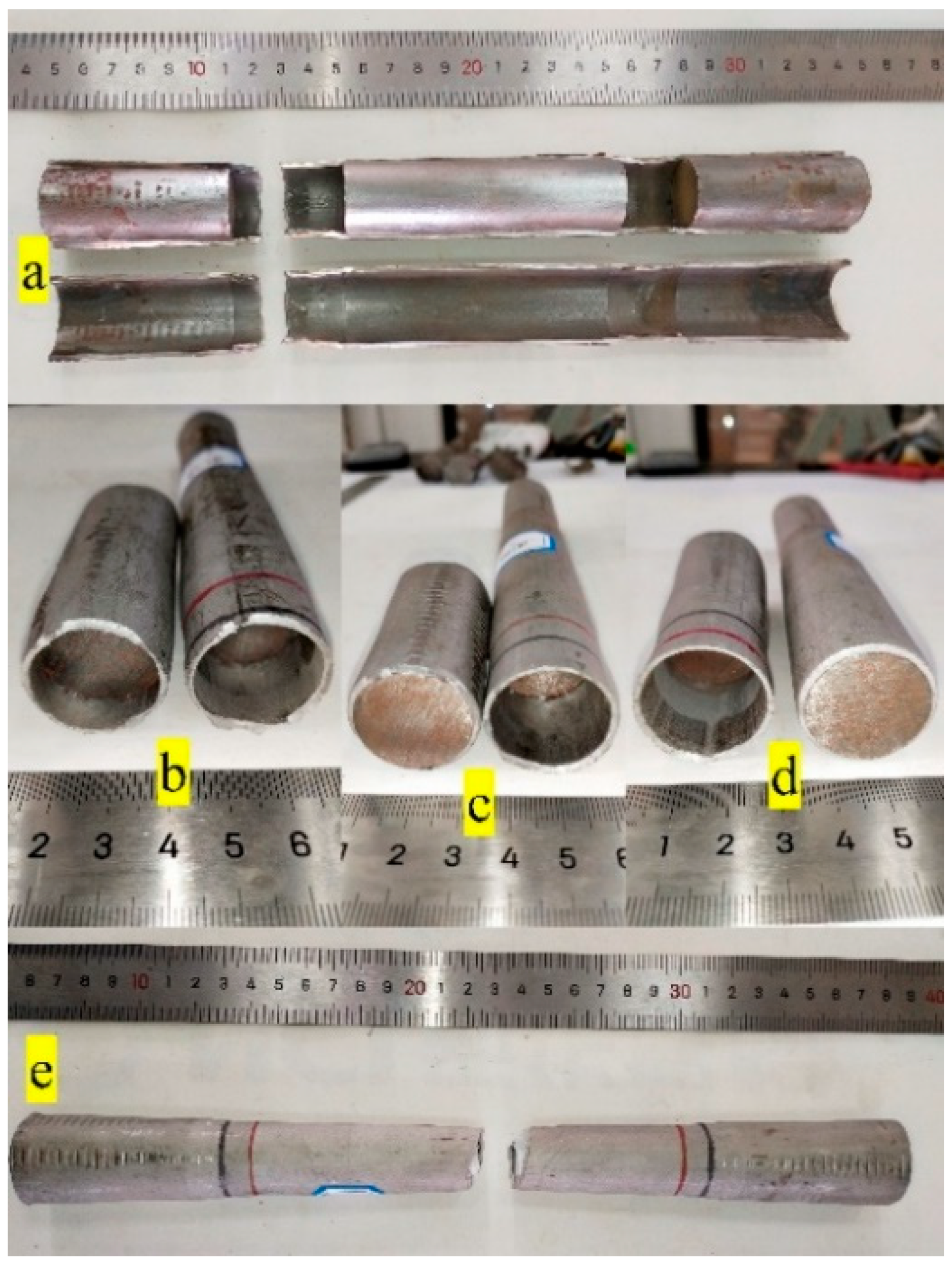
- Two fracture modes were obtained: the middle fracture mode and the clamping-side fracture mode. Under the middle fracture mode, internal support had a positive effect on the ultimate strength and extension of tubes (only one case showed reduction). Under the clamping-side fracture mode, the effect of internal support had a negative effect on the ultimate strength under low loading rates and a positive effect under high loading rates. The effect on the tube extension was primarily negative.
- (3)
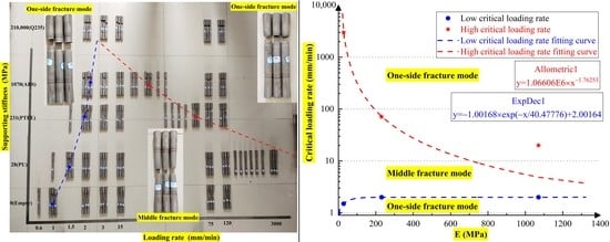
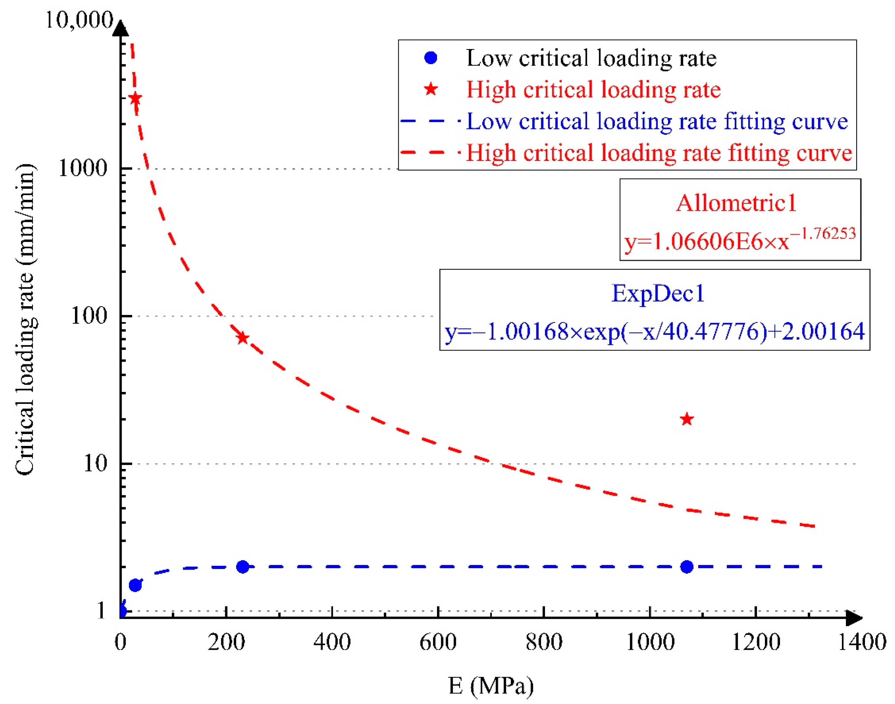
- Different internally filled specimens exhibited upper and lower critical loading rates where the fracture mode switched. The upper critical loading rate was more sensitive to the variations in the tube filler stiffness, whereas the lower critical loading rate was insensitive to these variations. When the loading rate was between the upper and lower critical loading rates, the failure of the composite structure corresponded to the middle fracture mode, which facilitated an improvement in the ultimate tensile properties of composite structures. Under flexible internal support, the applicable loading rate of the middle fracture mode had a wide range. As the tube filler stiffness increased, the range of loading rate gradually decreased. When the elastic modulus of the tube filler was greater than a certain value (estimated to be 1.77 GPa), the 304 SSTWTs could only be fractured near the clamping side.
- (4)
- Given the increase in the mechanical properties and the fracture mode, flexible support was found to be better than rigid support for improving the ultimate tensile properties of tubes to a certain extent. Among the three flexible tube fillers tested, PU exhibited the best overall performance. Using PU as the tube filler, the UNTS, extension, and fracture energy of the tube at a loading rate of 15 mm/min were enhanced by 8.12%, 18.78%, and 26.01%, respectively, without significantly affecting the weight and cost. Additionally, the applicable range of loading rate was wide.
Author Contributions
Funding
Institutional Review Board Statement
Informed Consent Statement
Data Availability Statement
Acknowledgments
Conflicts of Interest
Notations
| Original external diameter of tube (mm) | |
| Original internal diameter of tube (mm) | |
| Wall thickness of tube (mm) | |
| Original cross-sectional area (mm2) | |
| Original gauge length (mm) | |
| Parallel length (mm) | |
| Clamping length (mm) | |
| Total length of test piece (mm) | |
| Length of plug head (mm) | |
| Elastic modulus (MPa) | |
| Density of filler (kg/m3) | |
| N | Axial tensile force (N) |
| SSTWT | Stainless steel thin-walled tube |
| UNTS | Ultimate nominal tensile strength |
| CFST | Concrete-filled steel tubes |
| CFDST | Concrete-filled double-skin steel tube |
| SCFST | Squared concrete-filled steel tubes |
| CCFST | Circular concrete-filled steel tube |
| CFSST | Concrete-filled stainless steel tube |
| STD | Standard deviation |
| Longitudinal tensile stress (MPa) | |
| Transverse tensile stress (MPa) | |
| Ultimate tensile breaking strength of hollow tube (MPa) | |
| Ultimate longitudinal fracture stress (MPa) | |
| Contact compressive stress (MPa) | |
| Longitudinal shear stress (MPa) | |
| Transverse shear stress on the gripping side (MPa) | |
| Longitudinal shear stress in the middle of the tube (MPa) | |
| Loading rate (mm/min) | |
| Loading rate range of middle fracture modes (mm/min) | |
| Second invariant of deviatoric stress |
References
- Liu, S.; Ding, X.; Li, X.; Liu, Y.; Zhao, S. Behavior of Rectangular-Sectional Steel Tubular Columns Filled with High-Strength Steel Fiber Reinforced Concrete Under Axial Compression. Materials 2019, 12, 2716. [Google Scholar] [CrossRef] [PubMed]
- Alatshan, F.; Osman, S.A.; Mashiri, F.; Hamid, R. Explicit Simulation of Circular CFST Stub Columns with External Steel Confinement under Axial Compression. Materials 2020, 13, 23. [Google Scholar] [CrossRef] [PubMed]
- Lv, J.; Zhou, T.; Du, Q.; Li, K.; Jin, L. Research on the Bond Behavior of Preplaced Aggregate Concrete-Filled Steel Tube Columns. Materials 2020, 13, 300. [Google Scholar] [CrossRef] [PubMed]
- Yang, Z.; Xu, C. Research on Compression Behavior of Square Thin-Walled CFST Columns with Steel-Bar Stiffeners. Appl. Sci. 2018, 8, 1602. [Google Scholar] [CrossRef]
- Zhao, L.; Cao, W.; Guo, H.; Zhao, Y.; Song, Y.; Yang, Z. Experimental and Numerical Analysis of Large-Scale Circular Concrete-Filled Steel Tubular Columns with Various Constructural Measures under High Axial Load Ratios. Appl. Sci. 2018, 8, 1894. [Google Scholar] [CrossRef]
- Ro, K.M.; Kim, M.S.; Lee, Y.H. Experimental Study on Seismic Retrofitting of Reinforced Concrete Frames Using Welded Concrete-Filled Steel Tubes. Appl. Sci. 2020, 10, 7061. [Google Scholar] [CrossRef]
- Wang, T. Research on Seismic Performance of Hollow Sandwich Steel Tube Concrete Column after High Temperature. Tsinghua University 2018. Available online: http://kns.cnki.net/KCMS/detail/detail.aspx?FileName=1019603183.nh&DbName=CMFD2020 (accessed on 1 June 2018). (In Chinese).
- Cai, Y.; Wang, X.-S.; Yuan, S.-J. Quantitative analysis of orange peel during tension of 6063 alloy spun tubes. Trans. Nonferrous Met. Soc. China 2018, 28, 858–865. [Google Scholar] [CrossRef]
- Khandelwal, H.; Singh, R.; Bind, A.; Sunil, S.; Chakravartty, J.; Ghosh, A.K.; Dhandharia, P.; Bhachawat, D.; Shekhar, R.; Kumar, S.J. Tensile properties and fracture toughness of Zr–2.5Nb alloy pressure tubes of IPHWR220. Nucl. Eng. Des. 2015, 293, 138–149. [Google Scholar] [CrossRef]
- Guo, K.; Meng, K.; Miao, D.; Wang, Q.; Zhang, C.; Wang, T. Effect of annealing on microstructure and tensile properties of skew hot rolled Ti–6Al–3Nb–2Zr–1Mo alloy tube. Mater. Sci. Eng. A 2019, 766, 138346. [Google Scholar] [CrossRef]
- Chen, J.; E, D.X.; Zhang, J. Research on crack propagation in the crack process of 1Cr18Ni9Ti tube under uniaxial tension. Acta Armamentarium 2013, 34, 865–868. (In Chinese) [Google Scholar] [CrossRef]
- Yang, B.; Sun, W.; Jiang, W.; Zhao, Y. Degradation of microstructure and tensile properties of 12Cr1MoV steel tubes after long service life. Mater. Mech. Eng. 2019, 43, 24–27. (In Chinese) [Google Scholar] [CrossRef]
- Qu, J.; Zhou, J.; Shi, M.; Tian, F.; Zhang, J.; Chen, X. Study on axial tensile properties of annealed and martensitic M5 zirconium alloy tubes. Titan. Ind. Prog. 2015, 32, 23–26. (In Chinese) [Google Scholar]
- Liu, Z.; Lu, Y.; Li, S.; Yi, S. Behavior of steel tube columns filled with steel-fiber-reinforced self-stressing recycled aggregate concrete under axial compression. Thin Walled Struct. 2020, 149, 106521. [Google Scholar] [CrossRef]
- Hao, Z.; Zhang, R.; Ma, L.; Alan, K.; Ning, G.; Li, Z.; Experimental study and numerical analysis of bearing capacity of steel tube filled concrete components with defects. Industrial Construction 2020. Available online: http://kns.cnki.net/kcms/detail/11.2068.tu.20200416.2025.002.html (accessed on 17 April 2018).
- Liu, J.; Qian, Y. Research on bearing capacity of external steel tube reinforced existed ferroconcrete column. Highway Eng 2016, 41, 107–112. (In Chinese) [Google Scholar]
- Zeng, L.; Li, L.; Xiao, P.; Zeng, J.; Liu, F. Experimental study of seismic performance of full-scale basalt FRP-recycled aggregate concrete-steel tubular columns. Thin Walled Struct. 2020, 151, 106185. [Google Scholar] [CrossRef]
- Xu, J.; Chen, Z.; Zhao, X.; DeMartino, C.; Ozbakkaloglu, T.; Xue, J. Seismic performance of circular recycled aggregate concrete-filled steel tubular columns: FEM modelling and sensitivity analysis. Thin Walled Struct. 2019, 141, 509–525. [Google Scholar] [CrossRef]
- Liu, J.; Mao, J.; Yu, Z.; Chen, Y.; Zhou, G.; Ren, D.; Zhang, S. Seismic behavior analysis of steel tube confined recycled concrete columns. Concrete 2018, 3, 1–7. (In Chinese) [Google Scholar]
- He, A.; Wang, F.; Zhao, O. Experimental and numerical studies of concrete-filled high-chromium stainless steel tube (CFHSST) stub columns. Thin Walled Struct. 2019, 144. [Google Scholar] [CrossRef]
- Javed, M.F.; Sulong, N.H.R.; Memon, S.A.; Rehman, S.K.U.; Khan, N.B. FE modelling of the flexural behaviour of square and rectangular steel tubes filled with normal and high strength concrete. Thin Walled Struct. 2017, 119, 470–481. [Google Scholar] [CrossRef]
- Wang, F.; Young, B.; Gardner, L. Compressive testing and numerical modelling of concrete-filled double skin CHS with austenitic stainless steel outer tubes. Thin Walled Struct. 2019, 141, 345–359. [Google Scholar] [CrossRef]
- Mahbod, M.; Asgari, M. Energy absorption analysis of a novel foam-filled corrugated composite tube under axial and oblique loadings. Thin Walled Struct. 2018, 129, 58–73. [Google Scholar] [CrossRef]
- Li, S.; Yang, X.; An, T.; Zheng, Y. Compression and energy absorption properties of thin-walled tube composite filled with aluminum foam. J. Aeronaut. Mater. 2019, 39, 120–127. (In Chinese) [Google Scholar]
- Yang, X.; Xu, J.; Zou, T.; Zhao, N.; Zong, R. Advances in the composite structure of aluminum foam filled metal thin-walled tube. Mater. Rev. 2019, 33, 3637–3643. (In Chinese) [Google Scholar]
- Huang, R.; Liu, Z.; Lu, G.; Yan, Q. Study on energy absorption properties of thin-walled circular tubes filled with aluminum foam under axial compression. J. Taiyuan Univ. Technol. 2016, 47, 101–107. (In Chinese) [Google Scholar]
- Liu, W.; Cheng, H.; Huang, X.; Pan, Z. Quasi-static compression behaviors of cylindrical tubes filled with open-cell aluminum foam. Explos. Shock Waves 2009, 29, 654–658. (In Chinese) [Google Scholar]
- Guo, L.; Yu, J.; Yang, G. Research on the quasi-static axial crushing behavior of foam-filled double cylindrical tubes. J. Exp. Mech. 2011, 26, 181–189. (In Chinese) [Google Scholar]
- Xu, Y.; Feng, Y.; Tang, J.; Zhang, C.; Yang, Q. Numerical simulation of vertical compressing experiments of thin-walled cylindrical aluminum alloy tubes filled with aluminum foam. Rare Metal Mater. Eng. 2011, 40, 875–879. (In Chinese) [Google Scholar]
- Li, Z.; Chen, R.; Lu, F. Comparative analysis of crashworthiness of empty and foam-filled thin-walled tubes. Thin Walled Struct. 2018, 124, 343–349. [Google Scholar] [CrossRef]
- Li, Z.; Yu, J.; Zheng, Z.; Guo, L. An experimental study on the crashworthiness of thin-walled tubes and their metallic foam-filled structures. J. Exp. Mech. 2012, 27, 77–86. (In Chinese) [Google Scholar]
- Han, L.-H.; He, S.-H.; Liao, F.-Y. Performance and calculations of concrete fidoilled steel tubes (CFST) under axial tension. J. Constr. Steel Res. 2011, 67, 1699–1709. [Google Scholar] [CrossRef]
- Zhou, M.; Fan, J.-S.; Tao, M.-X.; Nie, J. Experimental study on the tensile behavior of square concrete-filled steel tubes. J. Constr. Steel Res. 2016, 121, 202–215. [Google Scholar] [CrossRef]
- Xu, L.-Y.; Tao, M.-X.; Zhou, M. Analytical model and design formulae of circular CFSTs under axial tension. J. Constr. Steel Res. 2017, 133, 214–230. [Google Scholar] [CrossRef]
- Chen, J.; Wang, J.; Li, W. Experimental behaviour of reinforced concrete-filled steel tubes under eccentric tension. J. Constr. Steel Res. 2017, 136, 91–100. [Google Scholar] [CrossRef]
- Ye, Y.; Li, W.; Guo, Z.-X. Performance of concrete-filled stainless steel tubes subjected to tension: Experimental investigation. Thin Walled Struct. 2020, 148, 106602. [Google Scholar] [CrossRef]
- Pan, Y.; Zhong, S. Constitutive relation of concrete filled steel tube under axial tension. Ind. Constr. 1990, 4, 30–37. (In Chinese) [Google Scholar]
- Li, W.; Han, L.-H.; Chan, T.-M. Tensile behaviour of concrete-filled double-skin steel tubular members. J. Constr. Steel Res. 2014, 99, 35–46. [Google Scholar] [CrossRef]


| Chemical Composition (%) | ||||||
|---|---|---|---|---|---|---|
| C | Si | Mn | P | S | Ni | Cr |
| 0.065 | 0.54 | 1.27 | 0.033 | 0.019 | 8.02 | 17.32 |
| Tube Filler | Material | Empty | PU | PTFE | ABS | Q235 | Nominal Strain Rate (/s) | |||
|---|---|---|---|---|---|---|---|---|---|---|
| E (MPa) | / | 28 | 231 | 1070 | 210,000 | |||||
| Loading Rate (mm/min) | Fracture Mode | Middle | Middle | Middle | One-Side | Middle | One-Side | One-Side | ||
| UNTS (Mpa) UNTS = N/S0 | 2 | Average | 876.81 | 901.80 | 915.47 | 864.12 | 908.92 | 853.10 | 925.11 | 3.51 × 10⁻⁴ |
| STD | 12.72 | 31.80 | / | / | / | / | 5.60 | |||
| Increment | / | 2.85% | 4.41% | −1.45% | 3.66% | −2.70% | 5.51% | |||
| 3 | Average | 836.10 | 862.83 | 876.42 | / | 853.45 | 819.57 | 912.42 | 5.26 × 10⁻⁴ | |
| STD | 8.88 | 16.40 | 10.42 | / | / | / | 26.57 | |||
| Increment | / | 3.20% | 4.82% | / | 2.08% | −1.98% | 9.13% | |||
| 15 | Average | 766.11 | 828.31 | 848.94 | / | 831.30 | / | 882.44 | 2.63 × 10⁻³ | |
| STD | 4.89 | 15.68 | 10.07 | / | 7.67 | / | 15.86 | |||
| Increment | / | 8.12% | 10.81% | / | 8.51% | / | 15.18% | |||
| 75 | Average | 750.32 | 799.16 | / | 812.95 | / | 802.19 | 851.15 | 1.32 × 10⁻² | |
| STD | 3.43 | 7.52 | / | 11.62 | / | 7.13 | 17.99 | |||
| Increment | / | 6.51% | / | 8.35% | / | 6.91% | 13.44% | |||
| 120 | Average | 744.39 | 799.28 | / | 785.26 | / | 806.89 | 814.44 | 2.11 × 10⁻² | |
| STD | 16.98 | 13.81 | / | 6.60 | / | 10.19 | 13.75 | |||
| Increment | / | 7.37% | / | 5.49% | / | 8.40% | 9.41% | |||
| Loading rate range of the middle fracture modes (mm/min) | 1–?? | 1.5–X X > 3000 | 2–71 | 2–20 | None | / | ||||
| Tube Filler | Material | Empty | PU | PTFE | ABS | Q235 | Nominal Strain Rate (/s) | |||
|---|---|---|---|---|---|---|---|---|---|---|
| E ( MPa) | / | 28 | 231 | 1070 | 210,000 | |||||
| Loading Rate (mm/min) | Fracture Mode | Middle | Middle | Middle | One-Side | Middle | One-Side | One-Side | ||
| Extension (mm) | 2 | Average | 77.52 | 78.86 | 84.87 | 71.56 | 79.98 | 67.74 | 58.45 | 3.51 × 10⁻⁴ |
| STD | 1.60 | 3.28 | / | / | / | / | 2.28 | |||
| Increment | / | 1.73% | 9.48% | −7.69% | 3.17% | −12.62% | −24.60% | |||
| 3 | Average | 76.05 | 82.25 | 83.99 | / | 71.64 | 67.18 | 56.81 | 5.26 × 10⁻⁴ | |
| STD | 0.80 | 1.48 | 1.00 | / | / | / | 3.09 | |||
| Increment | / | 8.15% | 10.44% | / | −5.80% | −11.66% | −25.30% | |||
| 15 | Average | 62.37 | 74.08 | 76.90 | / | 77.69 | / | 58.37 | 2.63 × 10⁻³ | |
| STD | 0.66 | 1.31 | 1.54 | / | 0.03 | / | 0.50 | |||
| Increment | / | 18.78% | 23.30% | / | 24.56% | / | −6.41% | |||
| 75 | Average | 63.23 | 68.00 | / | 72.82 | / | 61.31 | 56.18 | 1.32 × 10⁻² | |
| STD | 1.73 | 0.66 | / | 1.81 | / | 4.94 | 2.27 | |||
| Increment | / | 7.54% | / | 15.17% | / | −3.04% | −11.15% | |||
| 120 | Average | 66.53 | 67.73 | / | 69.86 | / | 58.48 | 53.05 | 2.11 × 10⁻² | |
| STD | 2.29 | 0.41 | / | 0.35 | / | 1.89 | 3.58 | |||
| Increment | / | 1.80% | / | 5.01% | / | −12.10% | −20.26% | |||
| Loading rate range of the middle fracture modes (mm/min) | 1–?? | 1.5–X X > 3000 | 2–71 | 2–20 | None | / | ||||
| Tube Filler | Material | Empty | PU | PTFE | ABS | Q235 | Nominal Strain Rate (/s) | |||
|---|---|---|---|---|---|---|---|---|---|---|
| E (MPa) | / | 28 | 231 | 1070 | 210,000 | |||||
| Loading Rate (mm/min) | Fracture Mode | Middle | Middle | Middle | One-Side | Middle | One-Side | One-Side | ||
| Fractureenergy (J) | 2 | Average | 9853.54 | 10,400.80 | 11,275.25 | 8580.00 | 10,529.71 | 7988.67 | 7673.98 | 3.51 × 10⁻⁴ |
| STD | 136.69 | 641.50 | / | / | / | / | 247.48 | |||
| Increment | / | 5.55% | 14.43% | −12.92% | 6.86% | −18.93% | −22.12% | |||
| 3 | Average | 9413.00 | 10,277.59 | 10,748.17 | / | 8614.44 | 7456.34 | 7320.25 | 5.26 × 10⁻⁴ | |
| STD | 96.72 | 182.34 | 270.66 | / | / | / | 712.04 | |||
| Increment | / | 9.19% | 14.18% | / | −8.48% | −20.79% | −22.23% | |||
| 15 | Average | 7246.40 | 9131.48 | 9850.81 | / | 9843.59 | / | 7444.44 | 2.63 × 10⁻³ | |
| STD | 128.03 | 129.52 | 228.22 | / | 108.34 | / | 218.35 | |||
| Increment | / | 26.01% | 35.94% | / | 35.84% | / | 2.73% | |||
| 75 | Average | 7351.28 | 8384.58 | / | 9116.61 | / | 7472.98 | 7260.53 | 1.32 × 10⁻² | |
| STD | 191.45 | 53.46 | / | 381.64 | / | 695.83 | 409.33 | |||
| Increment | / | 14.06% | / | 24.01% | / | 1.66% | −1.23% | |||
| 120 | Average | 7616.14 | 8372.25 | / | 8378.41 | / | 7298.99 | 6579.16 | 2.11 × 10⁻² | |
| STD | 330.57 | 123.74 | / | 187.63 | / | 387.48 | 528.08 | |||
| Increment | / | 9.93% | / | 10.01% | / | −4.16% | −13.62% | |||
| Loading rate range of the middle fracture modes (mm/min) | 1–?? | 1.5–X X > 3000 | 2–71 | 2–20 | None | / | ||||
| Material | E (MPa) | (kg/m3) | (mm/min) | Maximum Increment (%) | Comprehensive Assessment | ||
|---|---|---|---|---|---|---|---|
| UNTS (Middle) | Extension (Middle) | Fracture Energy (Middle) | |||||
| Q235 | 210,000 | 7867 | None | / | / | / | Worst |
| ABS | 1070 | 1044 | 2–20 | 8.51 | 24.56 | 35.84 | Third |
| PTFE | 231 | 2170 | 2–71 | 10.81 | 23.30 | 35.94 | Second |
| PU | 28 | 1103 | 1.5–X X > 3000 | 8.12 | 18.78 | 26.01 | Best |
| Authors | Ref. | Structure | (kg/m3) | E (MPa) | Loading Rate (mm/min) | Mechanical Property | Maximum Increment (%) | Note |
|---|---|---|---|---|---|---|---|---|
| Han et al. | [32] | CFST | 2200–2500 | 25,000–40,000 | 0.6 | Ultimate tensile strength | About 11 | |
| Zhou et al. | [33] | SCFST | 2 | Ultimate tensile strength | 5.2 | * | ||
| Ye et al. | [36] | CFSST | 0.6 | Ultimate tensile strength | 5–10 | Concentric tension | ||
| Pan et al. | [37] | CFST | / | Yield strength | 10 | |||
| Li et al. | [38] | CFDST | 5 | Ultimate tensile load | 20.8 | Concentric tension | ||
| Gao et al. | This study | PU | 1103 | 28 | 3 | Ultimate tensile strength | 3.20 | Middle fracture modes |
| Extension | 8.15 | |||||||
| Fracture energy | 9.19 | |||||||
| 15 | Ultimate tensile strength | 8.12 | ||||||
| Extension | 18.78 | |||||||
| Fracture energy | 26.01 |
Publisher’s Note: MDPI stays neutral with regard to jurisdictional claims in published maps and institutional affiliations. |
© 2020 by the authors. Licensee MDPI, Basel, Switzerland. This article is an open access article distributed under the terms and conditions of the Creative Commons Attribution (CC BY) license (http://creativecommons.org/licenses/by/4.0/).
Share and Cite
Gao, Y.; Shao, F.; Fan, P.; Xu, Q.; Xie, X. Effect of Internal Support on the Tensile Properties and Fracture Mode of 304 Stainless Steel Thin-Walled Tubes. Materials 2021, 14, 172. https://doi.org/10.3390/ma14010172
Gao Y, Shao F, Fan P, Xu Q, Xie X. Effect of Internal Support on the Tensile Properties and Fracture Mode of 304 Stainless Steel Thin-Walled Tubes. Materials. 2021; 14(1):172. https://doi.org/10.3390/ma14010172
Chicago/Turabian StyleGao, Yue, Fei Shao, Pengxian Fan, Qian Xu, and Xingkun Xie. 2021. "Effect of Internal Support on the Tensile Properties and Fracture Mode of 304 Stainless Steel Thin-Walled Tubes" Materials 14, no. 1: 172. https://doi.org/10.3390/ma14010172
APA StyleGao, Y., Shao, F., Fan, P., Xu, Q., & Xie, X. (2021). Effect of Internal Support on the Tensile Properties and Fracture Mode of 304 Stainless Steel Thin-Walled Tubes. Materials, 14(1), 172. https://doi.org/10.3390/ma14010172