An Amplitude- and Temperature-Dependent Vibration Model of Fiber-Reinforced Composite Thin Plates in a Thermal Environment


Abstract

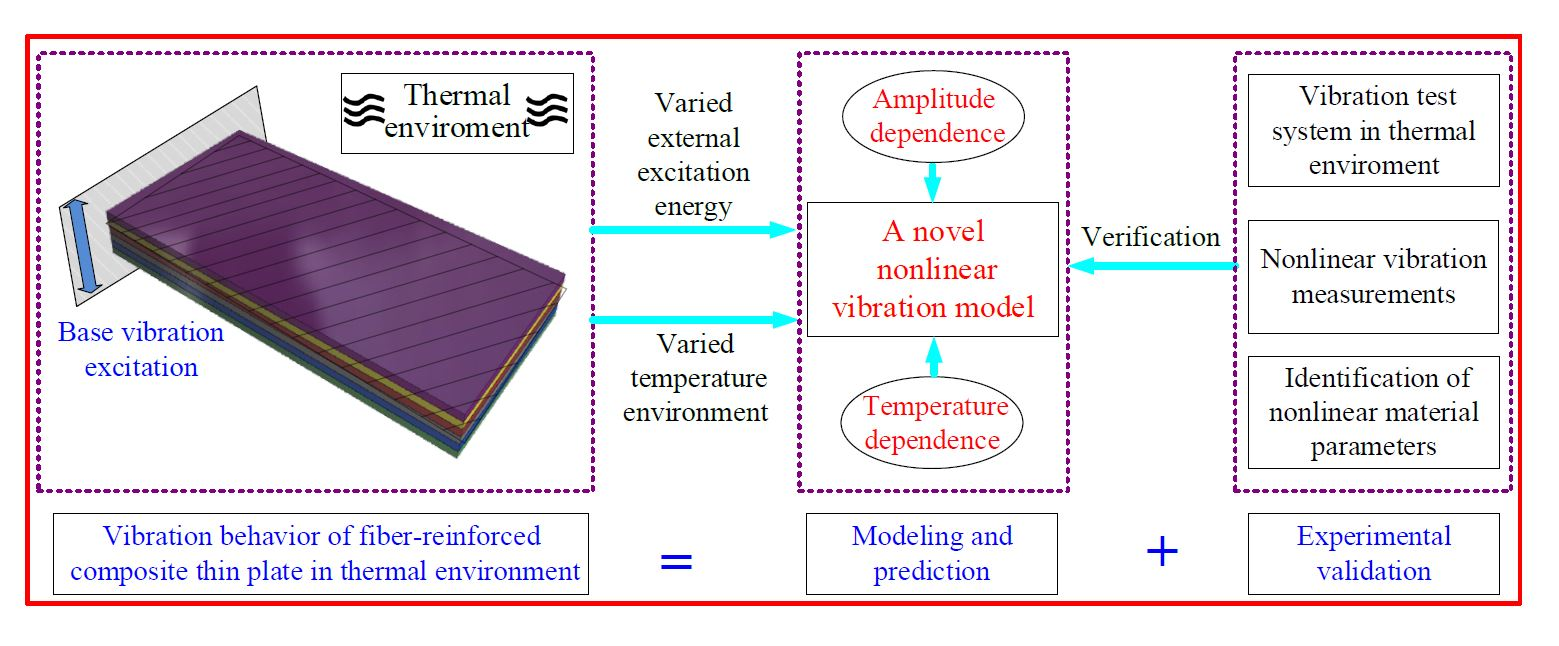
1. Introduction
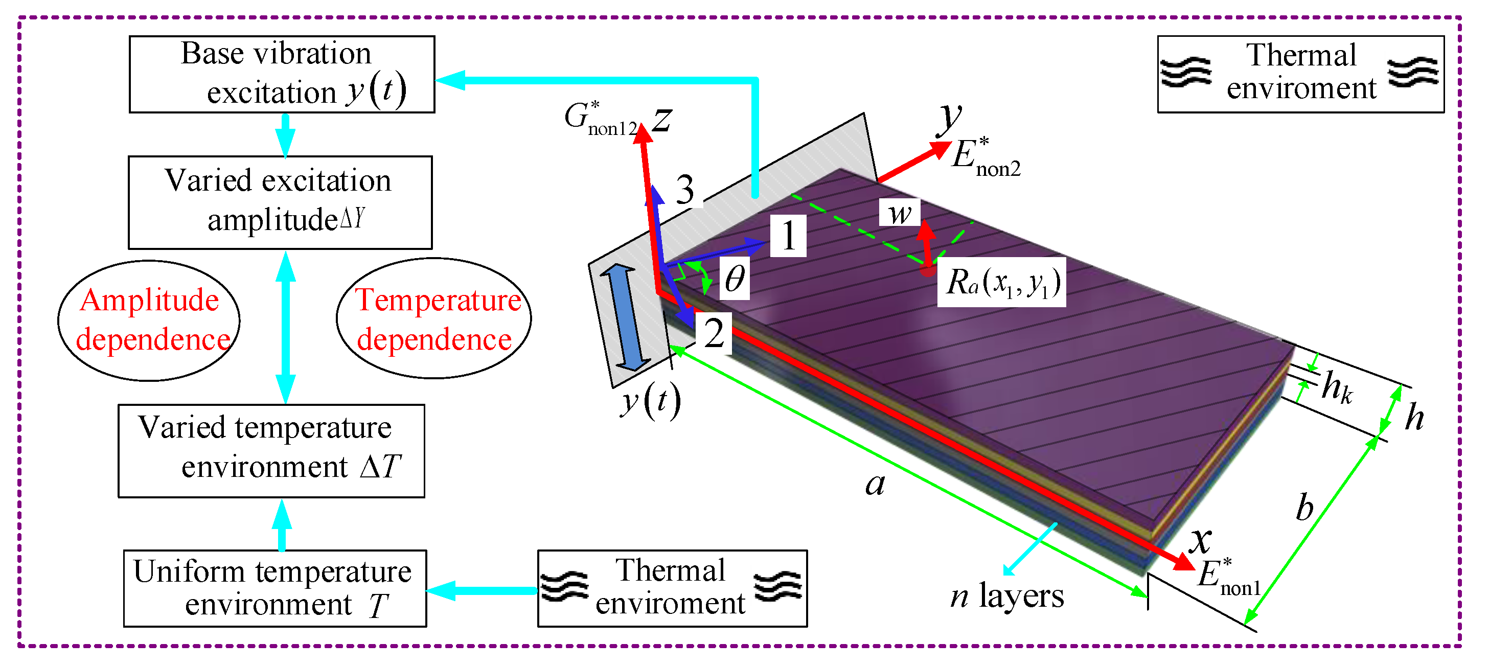
2. Modelling and Solutions
2.1. Model Descriptions and Energy Expressions
2.2. Solutions of the Nonlinear Vibration Parameters with Amplitude and Temperature Dependence
3. Determination of Nonlinear Fitting Coefficients in the Theoretical Model
3.1. Identify the Nonlinear Elastic Moduli and Loss Factors under Different Excitation Amplitudes and Temperatures
3.2. Determine the Nonlinear Stiffness and Damping Fitting Coefficients
4. A Case Study
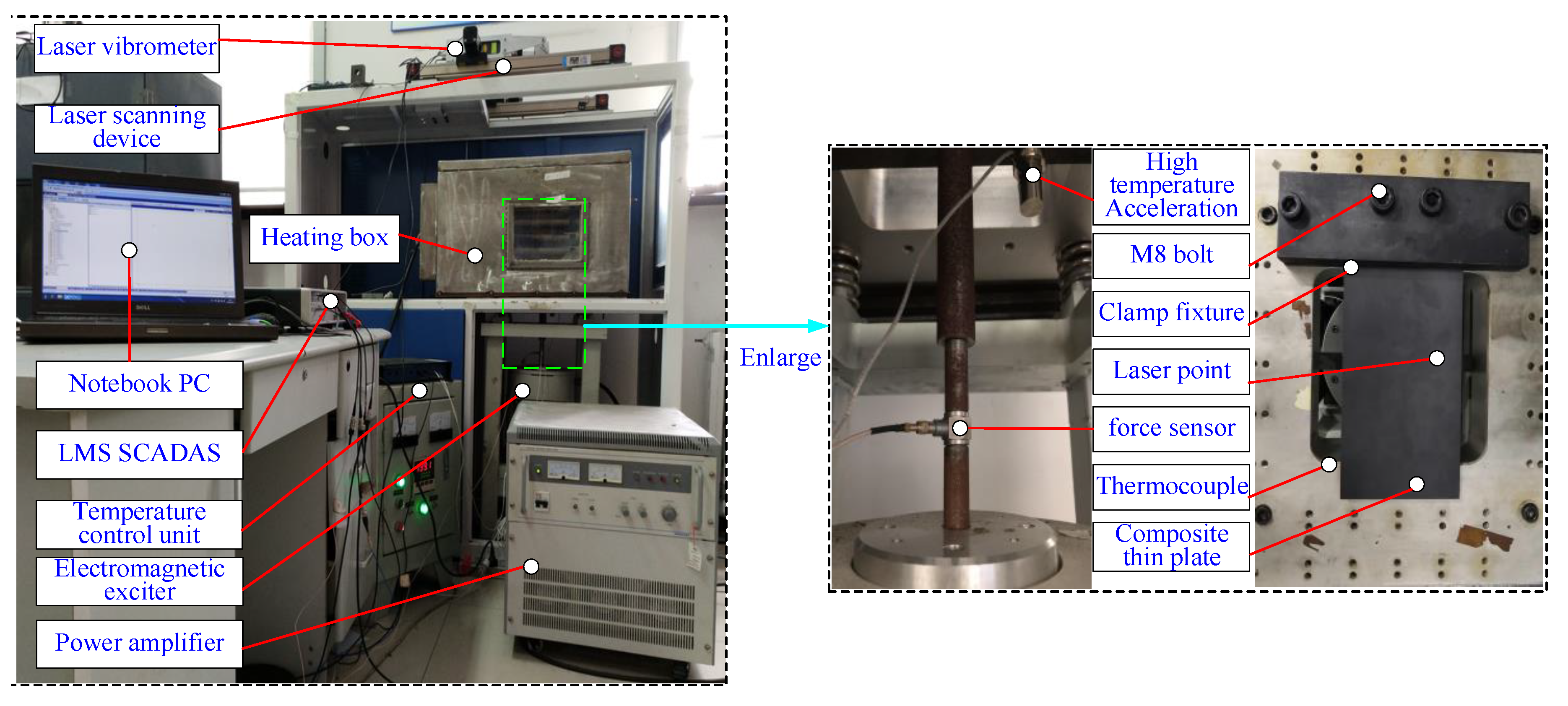
4.1. Test Specimen and System
4.2. Linear Measurements of Inherent Vibration Characteristics
4.3. Nonlinear Vibration Measurements under Different Excitation Amplitude and Temperature Conditions
4.4. Identification of Nonlinear Material Parameters
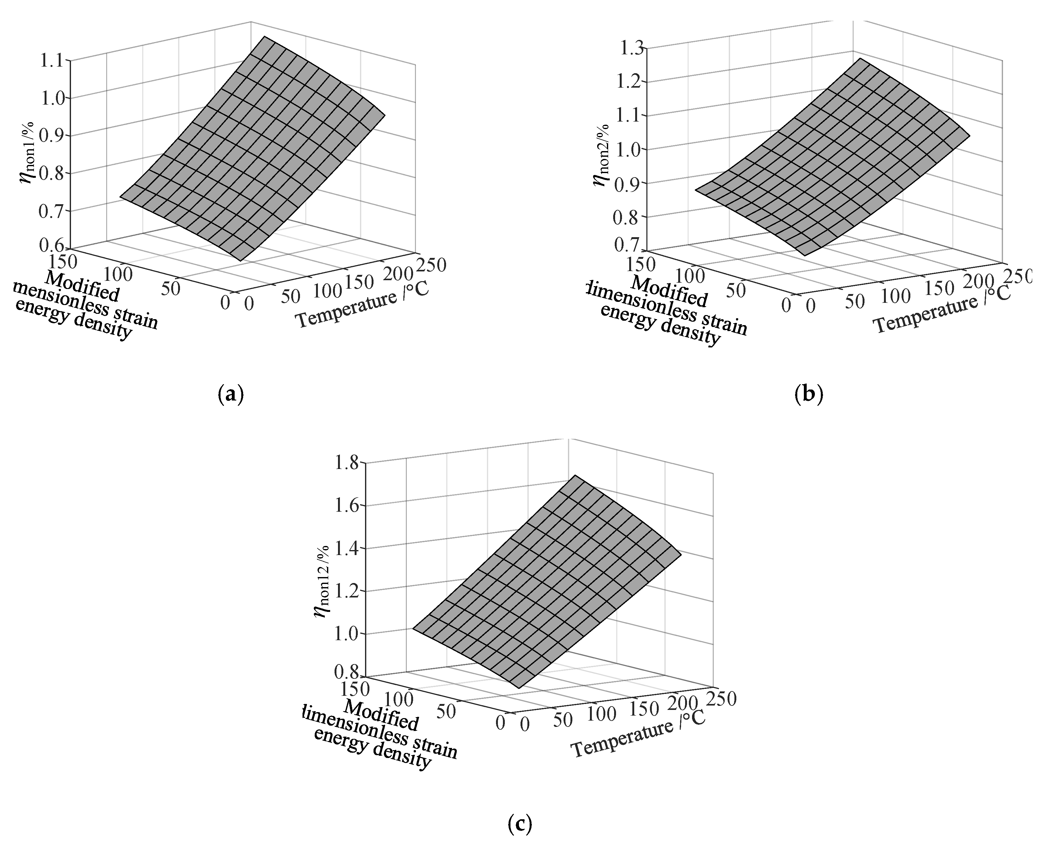
4.5. Data Fitting of Nonlinear Stiffness and Damping Coefficients
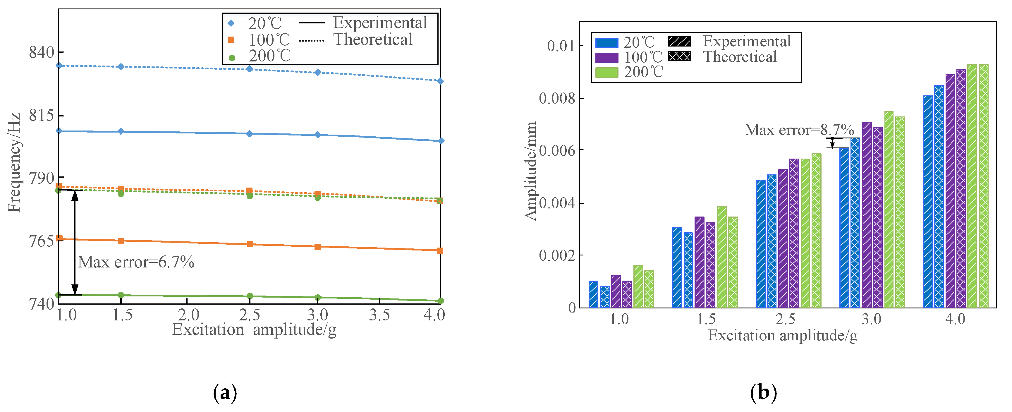
4.6. Comparison and Verification of the Amplitude and Temperature Dependent Model
5. Conclusions
Author Contributions
Funding
Conflicts of Interest
Nomenclature
| plane area | |
| length, width and thickness of FCTP | |
| nonlinear amplitude fitting coefficients related to elastic moduli and loss factors | |
| nonlinear amplitude fitting coefficients related to loss factors of fiber-reinforced composites | |
| complex elastic moduli in 1 and 2 directions of the fibers in a thermal environment | |
| nonlinear elastic moduli (considering amplitude and temperature) and traditional elastic moduli | |
| complex shear modulus in the 1–2 plane | |
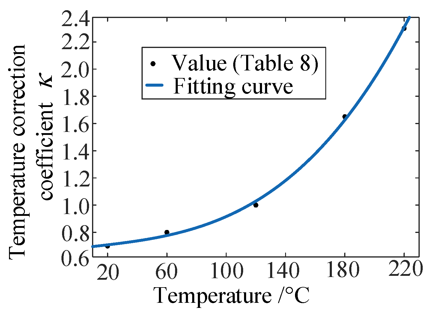
| temperature correction coefficient | |
| plate curvatures | |
| number of modes | |
| error accuracy factor | |
| temperature | |
| variation of temperature | |
| kinetic energy | |
| strain energy density of the composite structure | |
| constant of strain energy density which can make dimensionless | |
| strain energy | |
| excitation angular frequency | |
| vibration displacement | |
| nonlinear vibration response | |
| modal functions along x and y directions | |
| base excitation amplitude | |
| varied excitation amplitude | |
| base excitation load | |
| total complex strain energy | |
| complex strain energy along the ,, and directions | |
| ,, | strain energy along the ,, and directions |
| , , | dissipated energy along the ,, and directions |
| thermal expansion coefficients along the ,, and directions | |
| nonlinear thermal fitting coefficients related to elastic moduli and loss factors | |
| nonlinear thermal fitting coefficients related to loss factors | |
| angle between the 1 direction of the fibers and x-axis | |
| density | |
| loss factors with and without considering amplitude and temperature dependence | |
| mid-plane strains | |
| natural frequency obtained in the experiments and calculations in the ith mode of FCTP | |
| measured and calculated modal damping ratios in the ith mode of FCTP | |
| number of modes | |
| Lagrange energy function |
References
- Vinson, J.R.; Sierakowski, R.L. The Behavior of Structures Composed of Composite Materials; Springer Science & Business Media: Heidelberg, Germany, 2006. [Google Scholar]
- Li, H.; Niu, Y.; Li, Z.; Xu, Z.; Han, Q. Modeling of amplitude-dependent damping characteristics of fiber reinforced composite thin plate. Appl. Math. Model. 2020, 80, 394–407. [Google Scholar] [CrossRef]
- Tsai, Y.; Bosze, E.; Barjasteh, E.; Nutt, S. Influence of hygrothermal environment on thermal and mechanical properties of carbon fiber/fiberglass hybrid composites. Compos. Sci. Technol. 2009, 69, 432–437. [Google Scholar] [CrossRef]
- Jeyaraj, P.; Ganesan, N.; Padmanabhan, C. Vibration and acoustic response of a composite plate with inherent material damping in a thermal environment. J. Sound Vib. 2009, 320, 322–338. [Google Scholar] [CrossRef]
- Qiu, Z.; Wang, X.; Zhang, X.M.; Liu, J. A novel vibration measurement and active control method for a hinged flexible two-connected piezoelectric plate. Mech. Syst. Signal Process. 2018, 107, 357–395. [Google Scholar] [CrossRef]
- Lin, H.J.; Lee, Y.J. On the inelastic impact of composite laminated plate and shell structures. Compos. Struct. 1990, 14, 89–111. [Google Scholar] [CrossRef]
- Ovesy, H.R.; Fazilati, J. Stability analysis of composite laminated plate and cylindrical shell structures using semi-analytical finite strip method. Compos. Struct. 2009, 89, 467–474. [Google Scholar] [CrossRef]
- Qin, Z.Y.; Pang, X.J.; Safaei, B.; Chu, F.L. Free vibration analysis of rotating functionally graded CNT reinforced composite cylindrical shells with arbitrary boundary conditions. Compos. Struct. 2019, 220, 847–860. [Google Scholar] [CrossRef]
- Meunier, M.; Shenoi, R.A. Dynamic analysis of composite sandwich plates with damping modelled using high-order shear deformation theory. Compos. Struct. 2001, 54, 243–254. [Google Scholar] [CrossRef]
- Sulmoni, M.; Gmür, T.; Cugnoni, J.; Matter, M. Modal validation of sandwich shell finite element based on a p-order shear deformation theory including zigzag terms. Int. J. Numer. Methods Eng. 2008, 75, 1301–1319. [Google Scholar] [CrossRef]
- Pradyumna, S.; Bandyopadhyay, J.N. Dynamic instability behavior of laminated hypar and conoid shells using a higher-order shear deformation theory. Thin Walled Struct. 2011, 49, 77–84. [Google Scholar] [CrossRef]
- Qin, Z.Y.; Yang, Z.B.; Zu, J.; Chu, F.L. Free vibration analysis of rotating cylindrical shells coupled with moderately thick annular plate. Int. J. Mech. Sci. 2018, 142–143, 127–139. [Google Scholar] [CrossRef]
- Whitney, J.M.; Ashton, J.E. Effect of environment on the elastic response of layered composite plates. AIAA J. 1971, 9, 1708–1713. [Google Scholar] [CrossRef]
- Tauchert, T.R. Thermally induced flexure, buckling, and vibration of plates. Appl. Mech. Rev. 1991, 44, 347–360. [Google Scholar] [CrossRef]
- Ram, K.S.; Sinha, P.K. Hygrothermal effects on the free vibration of laminated composite plates. J. Sound Vib. 1992, 158, 133–148. [Google Scholar] [CrossRef]
- Liu, C.F.; Huang, C.H. Free vibration of composite laminated plates subjected to temperature changes. Comput. Struct. 1996, 60, 95–101. [Google Scholar] [CrossRef]
- Matsunaga, H. Free vibration and stability of angle-ply laminated composite and sandwich plates under thermal loading. Compos. Struct. 2007, 77, 249–262. [Google Scholar] [CrossRef]
- Praveen, G.N.; Reddy, J.N. Nonlinear transient thermoelastic analysis of functionally graded ceramic-metal plates. Int. J. Solids Struct. 1998, 35, 4457–4476. [Google Scholar] [CrossRef]
- Fakhari, V.; Ohadi, A.; Yousefian, P. Nonlinear free and forced vibration behavior of functionally graded plate with piezoelectric layers under thermal environment. Compos. Struct. 2011, 93, 2310–2321. [Google Scholar] [CrossRef]
- Jagtap, K.R.; Lal, A.; Singh, B.N. Stochastic nonlinear free vibration analysis of elastically supported functionally graded materials plate with system randomness under thermal environment. Compos. Struct. 2011, 93, 3185–3199. [Google Scholar] [CrossRef]
- Fu, Y.; Chen, Y.; Zhong, J. Analysis of nonlinear dynamic response for delaminated fiber–metal laminated beam under unsteady temperature field. J. Sound Vib. 2014, 333, 5803–5816. [Google Scholar] [CrossRef]
- Duc, N.D.; Cong, P.H.; Quang, V.D. Nonlinear dynamic and vibration analysis of piezoelectric eccentrically stiffened FGM plates under thermal environment. Int. J. Mech. Sci. 2016, 115–116, 711–722. [Google Scholar] [CrossRef]
- Gao, K.; Gao, W.; Wu, D.; Song, C. Nonlinear dynamic characteristics and stability of composite orthotropic plate on elastic foundation under thermal environment. Compos. Struct. 2017, 168, 619–632. [Google Scholar] [CrossRef]
- Chen, J.K.; Sun, C.T.; Chang, C.I. Failure Analysis of a Graphite/Epoxy Laminate Subjected to Combined Thermal and Mechanical Loading. J. Compos. Mater. 1985, 19, 408–423. [Google Scholar] [CrossRef]
- Akbulut, H.; Durman, M. Temperature-dependent strength analysis of short fiber reinforced Al–Si metal matrix composites. Mater. Sci. Eng. A 1999, 262, 214–226. [Google Scholar] [CrossRef]
- Melo, J.D.; Radford, D.W. Time and temperature dependence of the viscoelastic properties of CFRP by dynamic mechanical analysis. Compos. Struct. 2005, 70, 240–253. [Google Scholar] [CrossRef]
- Shariyat, M. Thermal buckling analysis of rectangular composite plates with temperature-dependent properties based on a layerwise theory. Thin Walled Struct. 2007, 45, 439–452. [Google Scholar] [CrossRef]
- Cao, S.; Wang, X.; Wu, Z. Evaluation and prediction of temperature-dependent tensile strength of unidirectional carbon fiber-reinforced polymer composites. J. Reinf. Plast. Compos. 2011, 30, 799–807. [Google Scholar]
- Abdelal, G.; Murphy, A. Nonlinear numerical modelling of lightning strike effect on composite panels with temperature-dependent material properties. Compos. Struct. 2014, 109, 268–278. [Google Scholar] [CrossRef]
- Manalo, A.; Maranan, G.; Sharma, S.; Karunasena, W.; Bai, Y. Temperature-sensitive mechanical properties of GFRP composites in longitudinal and transverse directions: A comparative study. Compos. Struct. 2017, 173, 255–267. [Google Scholar] [CrossRef]
- Pourasghar, A.; Moradi-Dastjerdi, R.; Yas, H.; Arani, A.G.; Kamarian, S. Three-dimensional analysis of carbon nanotube-reinforced cylindrical shells with temperature-dependent properties under thermal environment. Polym. Compos. 2018, 39, 1161–1171. [Google Scholar] [CrossRef]
- Cannella, F.; Garinei, A.; Marsili, R.; Speranzini, E. Dynamic mechanical analysis and thermoelasticity for investigating composite structural elements made with additive manufacturing. Compos. Struct. 2018, 185, 466–473. [Google Scholar] [CrossRef]
- Sefrani, Y.; Berthelot, J.M. Temperature effect on the damping properties of unidirectional glass fibre composites. Compos. Part B 2006, 37, 346–355. [Google Scholar] [CrossRef]
- Kar, V.R.; Panda, S.K. Free vibration responses of temperature-dependent functionally graded curved panels under thermal environment. Latin Am. J. Solids Struct. 2015, 12, 2006–2024. [Google Scholar] [CrossRef]
- Attia, A.; Tounsi, A.; Bedia, E.A.; Mahmoud, S.R. Free vibration analysis of functionally graded plates with temperature-dependent properties using various four variable refined plate theories. Steel Compos. Struct. 2015, 18, 187–212. [Google Scholar] [CrossRef]
- Taleb, O.; Houari, M.S.A.; Bessaim, A.; Tounsi, A.; Mahmoud, S.R. A new plate model for vibration response of advanced composite plates in a thermal environment. Struct. Eng. Mech. 2018, 67, 369–383. [Google Scholar]
- Fazzolari, F.A. Thermoelastic vibration and stability of temperature-dependent carbon nanotube-reinforced composite plates. Compos. Struct. 2018, 196, 199–214. [Google Scholar] [CrossRef]
- Li, H.; Wu, H.; Zhang, T.; Wen, B.; Guan, Z. A nonlinear dynamic model of fiber-reinforced composite thin plate with temperature dependence in a thermal environment. Compos. Part B Eng. 2019, 162, 206–218. [Google Scholar] [CrossRef]
- Kim, Y.; Lee, D.H. Identification of fractional-derivative-model parameters of viscoelastic materials from measured FRFs. J. Sound Vib. 2009, 324, 570–586. [Google Scholar] [CrossRef]
- Vasques, C.M.A.; Moreira, R.A.S.; Rodrigues, J.D. Viscoelastic damping technologies-Part I: Modeling and finite element implementation. J. Adv. Res. Mech. Eng. 2010, 1, 76–95. [Google Scholar]
- Li, H.; Xue, P.; Guan, Z.; Han, Q.; Wen, B. A new nonlinear vibration model of fiber-reinforced composite thin plate with amplitude-dependent property. Nonlinear Dyn. 2018, 94, 2219–2241. [Google Scholar] [CrossRef]
- Jones, R.M.; Nelson, D.A.R. A new material model for the nonlinear biaxial behavior of ATJ-S graphite. J. Compos. Mater. 1975, 9, 10–27. [Google Scholar] [CrossRef]
- Jones, M.; Morgan, H.S. Analysis of non-linear stress-strain behavior of fiber-reinforced composite materials. AIAA 1977, 15, 1669–1676. [Google Scholar] [CrossRef]
- Duc, N.D.; Quan, T.Q.; Khoa, N.D. New approach to investigate nonlinear dynamic response and vibration of imperfect functionally graded carbon nanotube reinforced composite double curved shallow shells subjected to blast load and temperature. Compos. Struct. 2017, 71, 360–372. [Google Scholar]
- Shen, H.; Xiang, Y. Nonlinear vibration of nanotube-reinforced composite cylindrical shells in a thermal environments. Compos. Struct. 2012, 213–216, 196–205. [Google Scholar] [CrossRef]
- Li, H.; Sun, W.; Zhu, M.; Xue, P. Experimental study on the influence on vibration characteristics of thin cylindrical shell with hard coating under cantilever boundary condition. Shock Vib. 2017, 2017, 1751870. [Google Scholar] [CrossRef]
- Li, H.; Niu, Y.; Mu, C.; Wen, B. Identification of loss factor of fiber-reinforced composite based on complex modulus method. Shock Vib. 2017, 2017, 6395739. [Google Scholar] [CrossRef]
- Alijani, F.; Amabili, M.; Balasubramanian, P.; Carra, S.; Ferrari, G.; Garziera, R. Damping for large-amplitude vibrations of plates and curved panels, part 1: Modeling and experiments. Int. J. Non Linear Mech. 2016, 85, 23–40. [Google Scholar] [CrossRef]
- Kar, V.R.; Panda, S.K. Large-amplitude vibration of functionally graded doubly-curved panels under heat conduction. AIAA J. 2017, 55, 1–11. [Google Scholar] [CrossRef]
- Li, H.; Chang, Y.; Xu, Z.; Zhu, Q.; Wen, B. Modal shape measurement of fiber-reinforced composite plate with high efficiency and precision based on laser linear scanning method. Meas. Control 2018, 51, 470–487. [Google Scholar] [CrossRef]
- Yin, H.P. A new theoretical basis for the bandwidth method and optimal power ratios for the damping estimation. Mech. Syst. Signal Process. 2008, 22, 1869–1881. [Google Scholar] [CrossRef]
- Bedon, C. Diagnostic analysis and dynamic identification of a glass suspension footbridge via on-site vibration experiments and FE numerical modelling. Compos. Struct. 2019, 216, 366–378. [Google Scholar] [CrossRef]


| Longitudinal Elastic Modulus (GPa) | Transverse Elastic Modulus (GPa) | Shear Modulus (GPa) | Poisson’s Ratio | Density (kg/m3) | Thermal Expansion Coefficient Parallel to Fibre Direction (/°C) | Thermal Expansion Coefficient Perpendicular to Fibre Direction (/°C) |
|---|---|---|---|---|---|---|
| 130 | 8.4 | 5.4 | 0.31 | 1780 | 0.15 × 10⁻⁶ | 1.3 × 10⁻⁶ |
| Device | Manufacturer | Product Model |
|---|---|---|
| Heating box | Changbai, Shenyang, China | T-500 |
| Laser vibrometer | Polytec, Germany | PDV-100 |
| High temperature accelerometer | Lianneng, jiangsu, China | CL-YD-301 |
| Electromagnetic exciter | Lianneng, jiangsu, China | JZK-100 |
| Power amplifier | Lianneng, jiangsu, China | YE5878 |
| Force sensor | NVT, Depew, NY, USA | PCB 208C03 |
| Mobile data acquisition system | LMS, Leuven, Belgium | LMS SCADAS |
| Modal Order | Temperature of 20 °C | Temperature of 220 °C | ||
|---|---|---|---|---|
| Natural Frequency (Hz) | Modal Shape | Natural Frequency (Hz) | Modal Shape | |
| 1 | 39.3 |  | 24.1 |  |
| 2 | 60.2 |  | 38.7 |  |
| 3 | 224.5 |  | 191.7 |  |
| 4 | 298.0 |  | 282.5 |  |
| 5 | 361.9 |  | 343.4 |  |
| 6 | 609.6 |  | 581.6 |  |
| Temperature (°C) | Category | Excitation Amplitude (g) | ||||
|---|---|---|---|---|---|---|
| 0.2 | 0.7 | 1.2 | 1.7 | 2.2 | ||
| 20 | Natural frequency (Hz) | 60.2 | 59.5 | 59.0 | 58 | 57.5 |
| Modal damping ratio (%) | 0.384 | 0.394 | 0.405 | 0.416 | 0.425 | |
| 60 | Natural frequency (Hz) | 56.5 | 55.8 | 55.3 | 54.4 | 54.1 |
| Modal damping ratio (%) | 0.403 | 0.416 | 0.428 | 0.440 | 0.450 | |
| 120 | Natural frequency (Hz) | 49.9 | 49.3 | 48.9 | 48.2 | 47.8 |
| Modal damping ratio (%) | 0.462 | 0.477 | 0.490 | 0.504 | 0.516 | |
| 180 | Natural frequency (Hz) | 44.6 | 44.1 | 43.6 | 43 | 42.7 |
| Modal damping ratio (%) | 0.536 | 0.553 | 0.569 | 0.585 | 0.599 | |
| 220 | Natural frequency (Hz) | 38.7 | 38.3 | 37.9 | 37.4 | 37.2 |
| Modal damping ratio (%) | 0.565 | 0.585 | 0.605 | 0.622 | 0.640 | |
| Temperature (°C) | Category | Excitation Amplitude (g) | ||||
|---|---|---|---|---|---|---|
| 0.5 | 1 | 1.25 | 1.75 | 2 | ||
| 20 | Natural frequency (Hz) | 298.0 | 296.5 | 295.5 | 293.9 | 293.0 |
| Modal damping ratio (%) | 0.337 | 0.349 | 0.356 | 0.366 | 0.373 | |
| 60 | Natural frequency (Hz) | 296.0 | 294.6 | 293.7 | 292.2 | 291.4 |
| Modal damping ratio (%) | 0.357 | 0.370 | 0.378 | 0.389 | 0.397 | |
| 120 | Natural frequency (Hz) | 287.9 | 286.6 | 285.8 | 284.4 | 283.7 |
| Modal damping ratio (%) | 0.402 | 0.416 | 0.426 | 0.438 | 0.448 | |
| 180 | Natural frequency (Hz) | 285.4 | 284.2 | 283.5 | 282.0 | 281.4 |
| Modal damping ratio (%) | 0.452 | 0.468 | 0.480 | 0.494 | 0.505 | |
| 220 | Natural frequency (Hz) | 282.5 | 281.5 | 280.9 | 279.7 | 279.2 |
| Modal damping ratio (%) | 0.493 | 0.510 | 0.522 | 0.538 | 0.550 | |
| Temperature (°C) | Category (GPa) | Excitation Amplitude (g) | ||||
|---|---|---|---|---|---|---|
| 0.5 | 1 | 1.25 | 1.75 | 2 | ||
| 20 | E1 | 129.90 | 129.44 | 129.20 | 128.68 | 128.37 |
| E2 | 8.51 | 8.24 | 8.08 | 7.71 | 7.51 | |
| G12 | 5.58 | 5.49 | 5.44 | 5.34 | 5.30 | |
| 60 | E1 | 126.68 | 126.23 | 126.01 | 125.51 | 125.21 |
| E2 | 8.20 | 7.95 | 7.79 | 7.42 | 7.23 | |
| G12 | 5.43 | 5.35 | 5.29 | 5.21 | 5.16 | |
| 120 | E1 | 121.01 | 120.56 | 120.35 | 119.90 | 119.60 |
| E2 | 7.51 | 7.29 | 7.14 | 6.79 | 6.62 | |
| G12 | 5.08 | 5.00 | 4.97 | 4.88 | 4.85 | |
| 180 | E1 | 114.42 | 114.02 | 113.83 | 113.43 | 113.17 |
| E2 | 6.77 | 6.58 | 6.44 | 6.11 | 5.96 | |
| G12 | 4.65 | 4.59 | 4.56 | 4.49 | 4.46 | |
| 220 | E1 | 109.47 | 109.11 | 108.94 | 108.58 | 108.34 |
| E2 | 6.11 | 5.95 | 5.83 | 5.52 | 5.39 | |
| G12 | 4.33 | 4.28 | 4.26 | 4.20 | 4.17 | |
| Temperature (°C) | Category (%) | Excitation Amplitude (g) | ||||
|---|---|---|---|---|---|---|
| 0.5 | 1 | 1.25 | 1.75 | 2 | ||
| 20 | 0.673 | 0.701 | 0.714 | 0.741 | 0.753 | |
| 0.806 | 0.838 | 0.854 | 0.884 | 0.899 | ||
| 0.904 | 0.952 | 0.976 | 1.025 | 1.049 | ||
| 60 | 0.720 | 0.749 | 0.766 | 0.795 | 0.809 | |
| 0.842 | 0.876 | 0.895 | 0.929 | 0.945 | ||
| 1.003 | 1.051 | 1.084 | 1.141 | 1.168 | ||
| 120 | 0.811 | 0.843 | 0.861 | 0.896 | 0.911 | |
| 0.925 | 0.962 | 0.981 | 1.019 | 1.036 | ||
| 1.161 | 1.219 | 1.253 | 1.323 | 1.355 | ||
| 180 | 0.907 | 0.942 | 0.961 | 1.002 | 1.020 | |
| 1.016 | 1.055 | 1.075 | 1.120 | 1.140 | ||
| 1.318 | 1.385 | 1.421 | 1.505 | 1.542 | ||
| 220 | 0.976 | 1.012 | 1.032 | 1.076 | 1.095 | |
| 1.084 | 1.124 | 1.145 | 1.193 | 1.214 | ||
| 1.432 | 1.500 | 1.537 | 1.629 | 1.669 | ||
| The Modified Dimensionless Strain Energy Density | Temperature (°C) | Excitation Amplitude (g) | ||||
|---|---|---|---|---|---|---|
| 0.5 | 1 | 1.25 | 1.75 | 2 | ||
| 20 | 12.0 | 39.8 | 56.6 | 95.0 | 115.6 | |
| 60 | 11.3 | 35.8 | 56.0 | 96.0 | 117.0 | |
| 120 | 10.5 | 37.0 | 54.2 | 96.1 | 117.2 | |
| 180 | 8.8 | 33.6 | 50.0 | 94.0 | 115.3 | |
| 220 | 9.9 | 32.8 | 49.0 | 93.0 | 114.5 | |
| Temperature Correction Coefficient | Temperature (°C) | ||||
|---|---|---|---|---|---|
| 20 | 60 | 120 | 180 | 220 | |
| 0.7 | 0.8 | 1 | 1.65 | 2.3 | |
| Material | Longitudinal Direction | Transverse Direction | Shear Direction | |||
|---|---|---|---|---|---|---|
| CF130 carbon/epoxy composite | 0.0002329 | 0.000389 | 0.0001658 | |||
| 1.23 | 1.243 | 1.358 | ||||
| A1 | 0.0000694 | A2 | 0.0009951 | A12 | 0.00117 | |
| B1 | 1.11 | B2 | 1.005 | B12 | 0.7924 | |
| −0.001149 | −0.0005482 | −0.002435 | ||||
| 1.129 | 1.22 | 1.037 | ||||
| C1 | −0.007079 | C2 | −0.0006355 | C12 | −0.006214 | |
| D1 | 0.6548 | D2 | 0.6691 | D12 | 0.737 | |
| Category | E1 (GPa) | E2 (GPa) | G12 (GPa) | η1 (%) | η2 (%) | η12 (%) |
|---|---|---|---|---|---|---|
| Value | 130 | 8.6 | 5.6 | 0.65 | 0.78 | 0.87 |
© 2020 by the authors. Licensee MDPI, Basel, Switzerland. This article is an open access article distributed under the terms and conditions of the Creative Commons Attribution (CC BY) license (http://creativecommons.org/licenses/by/4.0/).
Share and Cite
Zu, X.; Wu, H.; Lv, H.; Zheng, Y.; Li, H. An Amplitude- and Temperature-Dependent Vibration Model of Fiber-Reinforced Composite Thin Plates in a Thermal Environment. Materials 2020, 13, 1590. https://doi.org/10.3390/ma13071590
Zu X, Wu H, Lv H, Zheng Y, Li H. An Amplitude- and Temperature-Dependent Vibration Model of Fiber-Reinforced Composite Thin Plates in a Thermal Environment. Materials. 2020; 13(7):1590. https://doi.org/10.3390/ma13071590
Chicago/Turabian StyleZu, Xudong, Huaishuai Wu, Haiyu Lv, Yu Zheng, and Hui Li. 2020. "An Amplitude- and Temperature-Dependent Vibration Model of Fiber-Reinforced Composite Thin Plates in a Thermal Environment" Materials 13, no. 7: 1590. https://doi.org/10.3390/ma13071590
APA StyleZu, X., Wu, H., Lv, H., Zheng, Y., & Li, H. (2020). An Amplitude- and Temperature-Dependent Vibration Model of Fiber-Reinforced Composite Thin Plates in a Thermal Environment. Materials, 13(7), 1590. https://doi.org/10.3390/ma13071590