Complex Catalytic Materials Based on the Perovskite-Type Structure for Energy and Environmental Applications


Abstract
1. Introduction
2. General Aspects Concerning Perovskites Materials
2.1. Inorganic Perovskites
2.2. Hybrid Organic-Inorganic Perovskites
3. Preparation of Inorganic Perovskite Materials
3.1. Preparation of Powders via Chemical Routes
3.1.1. Co-Precipitation Method
3.1.2. Synthesis from Amorphous Precursors—“Citrate” Method
3.1.3. Combustion Synthesis Method
3.1.4. Hydrothermal Synthesis
3.1.5. Solid State Reactions
3.1.6. Influence of the Preparation Method on the Specific Surface Area of the Perovskite-Type Materials
3.2. Thin Films Manufacturing Using Laser-Based Techniques
3.2.1. Pulsed Laser Deposition (PLD)
- the laser radiation can be well focused on very small spot sizes at the target surface, increasing in this way the efficiency, the control and the flexibility of the process;
- the deposition chamber can be considered a “clean reactor” because the energy source (laser) is external, being independent of the deposition medium; also, the laser parameters (energy density and wavelength) can be easily adjusted to ensure the reproducibility of the sample preparation;
- it is a simple and versatile technique from the point of view of experimental achievement, offering the possibility to obtain all kind of materials (complex stoichiometry, organo-metallic compounds);
- the properties of the obtained thin films (thickness, crystalline structure, stoichiometry and composition) can be rigorously controlled, because they depend on the laser parameters (wavelength, laser fluence, the spot area, the duration of pulse, the repetition rate etc.) which are easily controlled from the outside of the deposition chamber;
- it ensures large deposition rates (1–5 Å/pulse).
- the possibility to cover only substrates having small area (~1 cm2);
- the selection of a suitable target material: a target made by dense and very small particles, ensures uniform conditions during the ablation process. A material presenting a lot of defects or different structural mechanical strains, which can appear during the processing procedure, affects the deposition process. Moreover, the target material has to present a high absorption coefficient at the used laser wavelength;
- the rotating and the translation of the target material toward the laser beam during the deposition process;
- the optimizing of the deposition parameters (the laser fluence, the laser spot area, the repetition rate);
- the utilization of a supplementary laser beam parallel to the substrate surface which can split the material clusters.
3.2.2. Matrix-Assisted Pulsed Laser Evaporation (MAPLE)
4. Catalytic Applications of Perovskite-Type Materials
4.1. Energy Production
4.1.1. The Production of Energy in the Form of Hydrogen via Water Photodecomposition
4.1.2. Catalytic Combustion of Methane
4.2. Applications of Perovskite-Type Materials in the Removal of Pollutants from Waste Waters
5. Conclusions and Perspectives
- ➢
- There are various synthesis methods for both powder and thin films, which determine their physicochemical properties. The specific surface area of the perovskite powders, which is a key characteristic of a solid catalyst, is strongly influenced by the preparation method used, but remains low. Indeed, the highest surface areas, mainly obtained by citrate and flame-pyrolysis methods, do not exceed several tens of m2/g. On the other hand, pulsed laser deposition is one of the most suitable preparation methods for inorganic perovskite thin films, due to its high material transfer efficiency, precise control and the great flexibility of the process. Depending on the experimental conditions, the stoichiometry of the material, as well as the thickness and the crystallinity of the films can be controlled. The most commonly used lasers for the preparation of perovskite films are those emitting in UV spectrum (193 nm, 248 nm and 355 nm). The films’ thickness starts from less than 1 nm and rises up to ca. 600 nm.
- ➢
- Oxide ferroelectric perovskites show excellent efficiency for the conversion of solar energy into chemical energy (H2) via water splitting. Both photocatalytic and photoelectrochemical systems are extensively studied in this application domain. The high spontaneous polarization of BiFeO3 is beneficial for a very efficient electron-hole separation. LaFeO3 presents strong absorption properties of visible light, which represents ca. 42% of the entire solar spectrum. The photoelectrodes are tested for a wide range of pH values, starting from semi-acidic to strong alkaline media. The highest photocurrent density (46.9 mA/cm2 at 2.53 VRHE) is obtained for a complex heterostructure based on WO3/BiBO4/BiFeO3. The best stability (more than 120 h) was reported in 1M NaOH for p-LaFeO3/n-Fe2O3.
- ➢
- Due to their good thermal stability, perovskite materials were successfully used in the catalytic combustion of methane for both power generation and methane emission abatement. Although the performance of pure perovskites is limited by their small specific surface area, their efficiency can be improved either by dispersion onto support materials possessing high surface area and thermal stability or by doping with other transition metals. Indeed, substitution in A and B sites of the perovskite structure with small amounts of other cations can improve both the stability and activity of the catalyst. Improved activity and stability can also be obtained by coating of the supported perovskite either on ceramic or metallic monoliths. The most used A-site dopants for perovskites are alkaline earth metals (Sr, Ca and Ba) and lanthanides (Ce, Eu), while for B-sites metals from the 3 and 4 periods (Mg, Al, Mn and Cu) in particular are preferred. The most active perovskites for the low-pressure methane combustion is La0.6Sr0.4MnO3 with a value of T50% of 360 °C. The high activity of this catalyst is due to its enhanced ability to adsorb oxygen on the surface.
- ➢
- The photodegradation of organic dyes on inorganic semiconducting perovskites showed excellent results. Their high stability under extreme chemical conditions, strong absorption properties and efficient charge separation lead to high photocatalytic activity even after several reaction cycles. Catalytic systems containing BiFeO3 perovskites as such or modified with different dopants exhibited an exceptionally high activity in the photocatalytic degradation of both anionic and cationic organic dyes.
Author Contributions
Funding
Conflicts of Interest
References
- Libby, W.F. Promising catalyst for auto exhaust. Science 1971, 171, 499–500. [Google Scholar] [CrossRef]
- Pedersen, L.A.; Libby, W.F. Unseparated rare earth cobalt oxides as auto exhaust catalysts. Science 1972, 176, 1355–1356. [Google Scholar] [CrossRef]
- McCartyt, J.G.; Wise, H. Perovskite catalysts for methane combustion. Catal. Today 1990, 8, 231–248. [Google Scholar] [CrossRef]
- Ladavos, A.K.; Pornonis, P.J. Catalytic combustion of methane on La2-xSrxNiO4-λ (x = 0.00–1.50) Perovskites prepared via the nitrate and citrate routes. J. Chem. Soc. Faraday Trans. 1992, 88, 2557–2562. [Google Scholar] [CrossRef]
- Li, X.; Liu, Y.; Deng, J.; Xie, S.; Zhao, X.; Zhang, Y.; Zhang, K.; Arandiyan, H.; Guo, G.; Dai, H. Enhanced catalytic performance for methane combustion of 3DOM CoFe2O4 by co-loading MnOx and Pd–Pt alloy nanoparticles. Appl. Surf. Sci. 2017, 403, 590–600. [Google Scholar] [CrossRef]
- Rajeshwar, K. Hydrogen generation at irradiated oxide semiconductor–solution interfaces. J. Appl. Electrochem. 2007, 37, 765–787. [Google Scholar] [CrossRef]
- Wang, W.; Tade, M.O.; Shao, Z. Research progress of perovskite materials in photocatalysis- and photovoltaics-related energy conversion and environmental treatment. Chem. Soc. Rev. 2015, 44, 5371–5408. [Google Scholar] [CrossRef] [PubMed]
- Ladavos, A.; Pomonis, P. Methane Combustion on Perovskites. In Perovskites and Related Mixed Oxides; Granger, P., Parvulescu, V.I., Kaliaguine, S., Prellier, W., Eds.; Wiley: Weinheim, Germany, 2016; pp. 367–388. [Google Scholar]
- Megaw, H.D. Crystal structure of double oxides of the perovskite type. Proc. Phys. Soc. 1946, 58, 340. [Google Scholar] [CrossRef][Green Version]
- Galasso, F.S. Structure of Perovskite-Type Compounds. In Structure, Properties and Preparation of Perovskite-Type Compounds, 1st ed.; Smoluchowski, R., Kurti, N., Eds.; Elsevier Pergamon Press Inc.: Oxford, UK, 1969; pp. 2–49. [Google Scholar]
- Goldschmidt, V.M. Die gesetze der krystallochemie. Naturwissenschaften 1926, 14, 477–485. [Google Scholar] [CrossRef]
- Pena, M.A.; Fierro, J.L.G. Chemical structures and performance of perovskite oxides. Chem. Rev. 2001, 101, 1981–2017. [Google Scholar] [CrossRef]
- Bhalla, A.S.; Guo, R.; Roy, R. The perovskite structure—A review of its role in ceramic science and technology. Mater. Res. Innov. 2000, 4, 3–26. [Google Scholar] [CrossRef]
- Poglitsch, A.; Weber, D. Dynamic disorder in methylammoniumtrihalogenoplumbates (II) observed by millimeter-wave spectroscopy. J. Chem. Phys. 1987, 87, 6373–6378. [Google Scholar] [CrossRef]
- Li, W.; Wang, Z.; Deschler, F.; Gao, S.; Friend, R.H.; Cheetham, A.K. Chemically diverse and multifunctional hybrid organic–inorganic perovskites. Nat. Rev. Mater. 2017, 2, 1–18. [Google Scholar] [CrossRef]
- Weber, D. CH3NH3PbX3, a Pb(II)-system with cubic perovskite structure. J. Chem. Sci. B 1978, 33, 1443–1445. [Google Scholar] [CrossRef]
- Kieslich, G.; Sun, S.; Cheetham, A.K. An extended tolerance factor approach for organic–inorganic perovskites. Chem. Sci. 2015, 6, 3430–3433. [Google Scholar] [CrossRef] [PubMed]
- Chen, J.C.; Wu, J.M. Dielectric properties and ac conductivities of dense single-phased BiFeO3 ceramics. Appl. Phys. Lett. 2007, 91, 182903. [Google Scholar] [CrossRef]
- Nakayam, S. LaFeO3 perovskite-type oxide prepared by oxide-mixing, co-precipitation and complex synthesis methods. J. Mater. Sci. 2001, 36, 5643–5648. [Google Scholar] [CrossRef]
- Muneeswaran, M.; Jegatheesan, P.; Giridharan, N.V. Synthesis of nanosized BiFeO3 powders by co-precipitation method. J. Exp. Nanosci. 2012, 8, 341–346. [Google Scholar] [CrossRef]
- Dhakad, M.; Rayalu, S.S.; Kumar, R.; Doggali, P.; Bakardjieva, S.; Subrt, J.; Mitsuhashi, T.; Haneda, H.; Labhsetwar, N. Low cost, ceria promoted perovskite type catalysts for diesel soot oxidation. Catal. Lett. 2008, 121, 137–143. [Google Scholar] [CrossRef]
- Huang, F.; Sun, X.; Zheng, Y.; Xiao, Y.; Zheng, Y. Facile coprecipitation synthesis of La0.6Sr0.4MnO3 perovskites with high surface area. Mater. Lett. 2017, 210, 287–290. [Google Scholar] [CrossRef]
- Gosavi, P.V.; Biniwale, R.B. Pure phase LaFeO3 perovskite with improved surface area synthesized using different routes and its characterization. Mater. Chem. Phys. 2010, 119, 324–329. [Google Scholar] [CrossRef]
- Delmon, B.; Devillers, M. Solid State Reactions. In Handbook of Heterogeneous Catalysis, 2nd ed.; Ertl, G., Knozinger, H., Schuth, F., Weitkamp, J., Eds.; Wiley: Weinheim, Germany, 2008; pp. 295–318. [Google Scholar]
- Esposito, S. “Traditional” sol-gel chemistry as a powerful tool for the preparation of supported metal and metal oxide catalysts. Materials 2019, 12, 668. [Google Scholar] [CrossRef] [PubMed]
- Shu, J.; Kaliaguine, S. Well-dispersed perovskite-type oxidation catalysts. Appl. Catal. B 1998, 16, 303–308. [Google Scholar] [CrossRef]
- Rida, K.; Benabbas, A.; Bouremmad, F.; Pen, M.A.; Sastre, E.; Martınez-Arias, A. Effect of calcination temperature on the structural characteristics and catalytic activity for propene combustion of sol–gel derived lanthanum chromite perovskite. Appl. Catal. A 2007, 327, 173–179. [Google Scholar] [CrossRef]
- Zhong, Z.; Chen, L.; Yan, Q.; Fu, X. Study on the preparation of nanometer perovskite-type complex oxide LaFeO3 by sol-gel method. Stud. Surf. Sci. Catal. 1995, 91, 647–655. [Google Scholar] [CrossRef]
- Wei, J.; Xue, D. Low-temperature synthesis of BiFeO3 nanoparticles by ethylenediaminetetraacetic acid complexing sol–gel process. Mater. Res. Bull. 2008, 43, 3368–3373. [Google Scholar] [CrossRef]
- Ghosh, S.; Dasgupta, S.; Sen, A.; Maiti, H.S. Low temperature synthesis of bismuth ferrite nanoparticles by a ferrioxalate precursor method. Mater. Res. Bull. 2005, 40, 2073–2079. [Google Scholar] [CrossRef]
- Wang, X.; Zhang, Y.; Wu, Z. Magnetic and optical properties of multiferroic bismuth ferrite nanoparticles by tartaric acid-assisted sol–gel strategy. Mater. Lett. 2010, 64, 486–488. [Google Scholar] [CrossRef]
- Liu, T.; Xu, Y. Synthesis of nanocrystalline LaFeO3 powders via glucose sol–gel route. Mater. Chem. Phys. 2011, 129, 1047–1050. [Google Scholar] [CrossRef]
- Dhal, G.; Dey, S.; Mohan, D.; Prasa, R. Solution combustion synthesis of perovskite-type catalysts for diesel engine exhaust gas purification. Mater. Today Proc. 2017, 4, 10489–10493. [Google Scholar] [CrossRef]
- Peñalva, J.; Lazo, A. Synthesis of bismuth ferrite BiFeO3 by solution combustion method. In Journal of Physics: Conference Series, Proceedings of the XVI Meeting of Physics, Lima, Peru, 2–4 August 2017; Ochoa, R., Salinas, E., Blas, H., Eds.; IOP Publishing: Bristol, UK, 2017; pp. 195–202. [Google Scholar]
- Biamino, S.; Badini, C. Combustion synthesis of lanthanum chromite starting from water solutions: Investigation of process mechanism by DTA–TGA–MS. J. Eur. Ceram. Soc. 2004, 24, 3021–3034. [Google Scholar] [CrossRef]
- Russo, N.; Fino, D.; Saracco, G.; Specchia, V. Promotion effect of Au on perovskite catalysts for the regeneration of diesel particulate filters. Catal. Today. 2008, 137, 306–311. [Google Scholar] [CrossRef]
- Shandilya, M.; Rai, R.; Singh, J. Review: Hydrothermal technology for smart materials. Appl. Ceram. 2016, 115, 354–376. [Google Scholar] [CrossRef]
- Niu, F.; Gao, T.; Zhang, N.; Chen, Z.; Huang, Q.; Qin, L.; Sun, X.; Huang, Y. Hydrothermal synthesis of BiFeO3 nanoparticles for visible light photocatalytic applications. Mater. Res. Bull. 2014, 59, 6–12. [Google Scholar] [CrossRef]
- Zheng, W.; Liu, R.; Peng, D.; Meng, G. Hydrothermal synthesis of LaFeO3 under carbonate-containing medium. Mater. Lett. 2000, 43, 19–22. [Google Scholar] [CrossRef]
- Assirey, E.A.R. Perovskite synthesis, properties and their related biochemical and industrial application. Saudi Pharm. J. 2019, 27, 817–829. [Google Scholar] [CrossRef]
- Perejón, A.; Murafa, N.; Sánchez-Jiménez, P.E.; Criado, J.M.; Subrt, J.; Diánez, M.J.; Pérez-Maqued, L.A. Direct mechanosynthesis of pure BiFeO3 perovskite nanoparticles: Reaction mechanism. J. Mater. Chem. C 2013, 1, 3551–3562. [Google Scholar] [CrossRef]
- Sorescu, M.; Xu, T.; Burnett, J.D.; Aitken, J.A. Investigation of LaFeO3 perovskite growth mechanism through mechanical ball milling of lanthanum and iron oxides. J. Mater. Sci. 2011, 46, 6709–6717. [Google Scholar] [CrossRef]
- Amador, C.; Martin de Juan, L. Strategies for structured particulate systems design. Comput. Aided Chem. Eng. 2016, 39, 509–579. [Google Scholar] [CrossRef]
- Popescu, I.; Sandulescu, I.; Redey, A.; Marcu, I.C. Study of the catalytic activity–semiconductive properties relationship for BaTiO3 and PbTiO3 perovskites, catalysts for methane combustion. Catal. Lett. 2011, 141, 445–451. [Google Scholar] [CrossRef]
- Arai, H.; Yamada, T.; Eguchi, K.; Seiyama, T. Catalytic combustion of methane over various perovskite-type oxides. Appl. Catal. 1986, 26, 265–276. [Google Scholar] [CrossRef]
- Majid, A.; Tunney, J.; Argue, S.; Post, M. The effect of preparation method and calcination temperature on the crystallite size and surface area of perovskite-type SrFeOx. J. Sol Gel Sci. Technol. 2004, 32, 323–326. [Google Scholar] [CrossRef]
- Saracco, G.; Scibilia, G.; Iannibello, A.; Baldi, G. Methane combustion on Mg-doped LaCrO, perovskite catalysts. Appl. Catal. B 1996, 8, 229–244. [Google Scholar] [CrossRef]
- Rosso, I.; Saracco, G.; Specchia, V.; Garrone, E. Sulphur poisoning of LaCr0.5−xMnxMg0.5O3 ∙ yMgO catalysts for methane combustion. Appl. Catal. B 2003, 40, 195–205. [Google Scholar] [CrossRef]
- Salomonsson, P.; Griffin, T.; Kasemo, B. Oxygen desorption and oxidation-reduction kinetics with methane and carbon monoxide over perovskite type metal oxide catalysts. Appl. Catal. A 1993, 194, 175–197. [Google Scholar] [CrossRef]
- Lisi, L.; Bagnasco, G.; Ciambelli, P.; De Rossi, S.; Porta, P.; Russo, G.; Turco, M. Perovskite-type oxides, II. Redox properties of LaMn1-xCuxO3 and LaCo1-xCuxO3 and methane catalytic combustion. J. Solid State Chem. 1999, 146, 176–183. [Google Scholar] [CrossRef]
- Ciambellia, P.; Palma, V.; Tikhov, S.F.; Sadykov, V.A.; Isupova, L.A.; Lisi, L. Catalytic activity of powder and monolith perovskites in methane combustion. Catal. Today 1999, 47, 199–207. [Google Scholar] [CrossRef]
- Alifanti, M.; Kirchnerova, J.; Delmon, B.; Klvana, D. Methane and propane combustion over lanthanum transition-metal perovskites: Role of oxygen mobility. Appl. Catal. A 2004, 262, 167–176. [Google Scholar] [CrossRef]
- Kirchnerova, J.; Klvana, D.; Vaillancourt, J.; Chaouki, J. Evaluation of some cobalt and nickel based perovskites prepared by freeze-drying as combustion catalysts. Catal. Lett. 1993, 21, 77–87. [Google Scholar] [CrossRef]
- Kirchenerov, J.; Klvana, D. Preparation and characterization of high surface perovskite electrocatalysts. Int. J. Hydrogen Energy 1994, 19, 501–506. [Google Scholar] [CrossRef]
- Cimino, S.; Lisi, S.; De Rossi, S.; Faticanti, M.; Porta, P. Methane combustion and CO oxidation on LaAl1−xMnxO3 perovskite-type oxide solid solutions. Appl. Catal. B 2003, 43, 397–406. [Google Scholar] [CrossRef]
- Baiker, A.; Marti, P.E.; Keusch, P.; Fritsch, E.; Relier, A. Influence of the A-Site cation in ACoO3 (A = La, Pr, Nd, perovskite-type oxides on catalytic activity for methane combustion. J. Catal. 1994, 146, 268–276. [Google Scholar] [CrossRef]
- Busca, G.; Daturi, M.; Finocchio, E.; Lorenzelli, V.; Ramis, G.; Willey, R.J. Transition metal mixed oxides as combustion catalysts: Preparation, characterization and activity mechanisms. Catal. Today 1997, 33, 239–249. [Google Scholar] [CrossRef]
- Kirchnerova, J.; Alifanti, M.; Delmon, B. Evidence of phase cooperation in the LaCoO3–CeO2–Co3O4 catalytic system in relation to activity in methane combustion. Appl. Catal. A 2002, 231, 65–80. [Google Scholar] [CrossRef]
- Yi, N.; Cao, Y.; Su, Y.; Dai, W.L.; He, H.Y.; Fan, K.N. Nanocrystalline LaCoO3 perovskite particles confined in SBA-15 silica as a new efficient catalyst for hydrocarbon oxidation. J. Catal. 2005, 230, 249–253. [Google Scholar] [CrossRef]
- Yamazoe, N.; Teraoka, Y. Oxidation catalysis of perovskites—Relationships to bulk structure and composition (valency, defect, etc.). Catal. Today 1990, 8, 175–199. [Google Scholar] [CrossRef]
- Rossetti, I.; Biffi, C.; Forni, L. Oxygen non-stoichiometry in perovskitic catalysts: Impact on activity for the flameless combustion of methane. Chem. Eng. J. 2010, 162, 768–775. [Google Scholar] [CrossRef][Green Version]
- Koirala, R.; Pratsinis, S.E.; Baiker, A. Synthesis of catalytic materials in flames: Opportunities and challenges. Chem. Soc. Rev. 2016, 45, 3053–3068. [Google Scholar] [CrossRef]
- Milt, V.G.; Spretz, R.; Ulla, M.A.; Lambardo, E.A. The nature of active sites for the oxidation of methane on La-based perovskites. Catal. Lett. 1996, 42, 57–63. [Google Scholar] [CrossRef]
- Wei, X.; Hug, P.; Figi, R.; Trottmann, M.; Weidenkaff, A.; Ferri, D. Catalytic combustion of methane on nano-structured perovskite-type oxides fabricated by ultrasonic spray combustion. Appl. Catal. B 2010, 94, 27–37. [Google Scholar] [CrossRef]
- Rossetti, I.; Forni, L. Catalytic flameless combustion of methane over perovskites prepared by flame–hydrolysis. Appl. Catal. B 2001, 33, 345–352. [Google Scholar] [CrossRef]
- Ding, Y.; Wang, S.; Zhang, L.; Chen, Z.; Wang, M.; Wang, S. A facile method to promote LaMnO3 perovskite catalyst for combustion of methane. Catal. Commun. 2017, 97, 88–92. [Google Scholar] [CrossRef]
- Lu, Y.; Eyssler, A.; Otal, E.H.; Matam, S.K.; Brunko, O.; Weidenkaff, A.; Ferri, D. Influence of the synthesis method on the structure of Pd-substituted perovskite catalysts for methane oxidation. Catal. Today 2013, 208, 42–47. [Google Scholar] [CrossRef]
- Lee, N.H.; Kim, J.H.; Oh, H.J.; Kim, S.J. In-Situ preparation of highly crystallized ZnO manopowders by ultrasonic spraying combustion method. Solid State Phenom. 2007, 121–123, 1269–1272. [Google Scholar] [CrossRef]
- Marti, P.E.; Baiker, A. Influence of the A-site cation in AMnO3+x and AFeO3+x (A = La, Pr, Nd and Gd) perovskite-type oxides on the catalytic activity for methane combustion. Catal. Lett. 1994, 26, 71–84. [Google Scholar] [CrossRef]
- Cimino, S.; Lisi, L.; Pirone, R.; Russo, G.; Turco, M. Methane combustion on perovskites-based structured catalysts. Catal. Today 2000, 59, 19–31. [Google Scholar] [CrossRef]
- Marchetti, L.; Forni, L. Catalytic combustion of methane over perovskites. Appl. Catal. B 1998, 15, 179–187. [Google Scholar] [CrossRef]
- Ciambelli, P.; Cimino, S.; De Rossi, S.; Faticanti, M.; Lisi, L.; Minelli, G.; Pettiti, I.; Porta, P.; Russo, G.; Turco, M. AMnO3 (A = La, Nd, Sm) and Sm1−xSrxMnO3 perovskites as combustion catalysts: Structural, redox and catalytic properties. Appl. Catal. B 2000, 24, 243–253. [Google Scholar] [CrossRef]
- Marti, P.E.; Maciejewski, M.; Baiker, A. Methane combustion over La0.8Sr0.2MnO3+x supported on MAl2O4 (M = Mg, Ni and Co) spinels. Appl. Catal. B 1994, 4, 225–235. [Google Scholar] [CrossRef]
- Wang, Y.; Arandiyan, H.; Tahini, H.A.; Scott, J.; Tan, X.; Dai, H.; Gale, J.D.; Rohl, A.L.; Smith, S.C.; Amal, R. The controlled disassembly of mesostructured perovskites as an avenue to fabricating high performance nanohybrid catalysts. Nat. Commun. 2017, 8, 15553. [Google Scholar] [CrossRef]
- Daturi, M.; Busca, G.; Groppi, G.; Forzatti, P. Preparation and characterisation of SrTil-x-yZrxMnyO3 solid solution powders in relation to their use in combustion catalysis. Appl. Catal. B 1997, 12, 325–337. [Google Scholar] [CrossRef]
- Pecchi, G.; Reyes, P.; Zamora, R.; Campos, C.; Cadus, L.E.; Barbero, B.P. Effect of the preparation method on the catalytic activity of La1-xCaxFeO3 perovskite-type oxides. Catal. Today 2008, 133–135, 420–427. [Google Scholar] [CrossRef]
- Ciambelli, P.; Cimino, S.; De Rossi, S.; Lisi, L.; Minelli, G.; Porta, P.; Russo, G. AFeO3 (A = La, Nd, Sm) and LaFe1−xMgxO3 perovskites as methane combustion and CO oxidation catalysts: Structural, redox and catalytic properties. Appl. Catal. B 2001, 29, 239–250. [Google Scholar] [CrossRef]
- Ciambelli, P.; Cimino, S.; Lisi, L.; Faticanti, M.; Minelli, G.; Pettiti, I.; Porta, P. La, Ca and Fe oxide perovskites: Preparation, characterization and catalytic properties for methane combustion. Appl. Catal. B 2001, 33, 193–203. [Google Scholar] [CrossRef]
- Pecchi, G.; Jiliberto, M.G.; Buljan, A.; Delgado, E.J. Relation between defects and catalytic activity of calcium doped LaFeO3 perovskite. Solid State Ion. 2011, 187, 27–32. [Google Scholar] [CrossRef]
- Kucharczyk, B.; Tylus, W. Partial substitution of lanthanum with silver in the LaMnO3 perovskite: Effect of the modification on the activity of monolithic catalysts in the reactions of methane and carbon oxide oxidation. Appl. Catal. A 2008, 335, 28–36. [Google Scholar] [CrossRef]
- Kucharczyk, B.; Okal, J.; Tylus, W.; Winiarski, J.; Szczygieł, B. The effect of the calcination temperature of LaFeO3 precursors on the properties and catalytic activity of perovskite in methane oxidation. Ceram. Int. 2019, 45, 2779–2788. [Google Scholar] [CrossRef]
- Specchia, S.; Toniato, G. Natural gas combustion catalysts for environmental-friendly domestic burners. Catal. Today 2009, 147, 99–106. [Google Scholar] [CrossRef]
- Klvanaa, D.; Kirchnerova, J.; Chaouki, J.; Delval, J.; Yaici, W. Fiber-supported perovskites for catalytic combustion of natural gas. Catal. Today 1999, 47, 115–121. [Google Scholar] [CrossRef]
- Pattini, F. Growth of Oxide Thin Films for Energy Devices by Pulsed Electron Deposition. Ph.D. Thesis, Università degli Studi di Parma, Parma, Italy, 2009. Available online: https://www.repository.unipr.it/handle/1889/1001 (accessed on 8 November 2020).
- Norton, D.P. Pulsed Laser Deposition of Complex Materials: Progress Toward Applications. In Pulsed Laser Deposition of Thin films; Eason, R., Ed.; Wiley: Hoboken, NJ, USA, 2007; pp. 3–28. [Google Scholar]
- Constantinescu, C.; Dinescu, M. Thin films development by pulsed laser-assisted deposition. Physics AUC 2010, 20, 43–56. [Google Scholar]
- Marozau, I.; Shkabko, A.; Dinescu, G.; Döbeli, M.; Lippert, T.; Logvinovich, D.; Malllepell, M.; Weidenkaff, A.; Wokaun, A. RF-plasma assisted pulsed laser deposition of nitrogen-doped SrTiO3 thin films. Appl. Phys. A 2008, 93, 721–727. [Google Scholar] [CrossRef]
- Beckers, L.; Schubert, J.; Zander, W.; Ziesmann, J.; Eckau, A.; Leinenbach, P.; Buchal, C. Structural and optical characterization of epitaxial wave guiding BaTiO3 thin films on MgO. J. Appl. Phys. 1998, 83, 3305–3310. [Google Scholar] [CrossRef]
- Mi, S.B.; Jia, C.L.; Heeg, T.; Trithaveesak, O.; Schubert, J.; Urban, K. Heterostructures of BaTiO3 bilayer films grown on SrTiO3 (001) under different oxygen pressures. J. Cryst. Growth 2005, 283, 425–430. [Google Scholar] [CrossRef]
- Berini, B.; Evain, M.; Fouchet, A.; Dumont, Y.; Popova, E.; Keller, N. In situ optical characterization of metal-insulator transition in LaNiO3 and SrTiO3 perovskites in pulsed laser deposition chamber. Phase Transit. 2011, 84, 501–508. [Google Scholar] [CrossRef]
- Cillessen, J.F.M.; Wolf, R.M.; Giesbers, J.B.; Blom, P.W.M.; Grosse-Holz, K.O.; Pastoor, E. Growth, structuring and characterisation of all-oxide thin film devices prepared by pulsed laser deposition. Appl. Surf. Sci. 1996, 96–98, 744–751. [Google Scholar] [CrossRef]
- Francis, A.; Salvador, P. Synthesis, structures, and physical properties of yttrium-doped strontium manganese oxide films. Mat. Res. Soc. Symp. Proc. 2002, 718, D9.4.1–D9.4.6. [Google Scholar] [CrossRef]
- Hawley, M.E.; Adams, C.D.; Arendt, P.N.; Brosha, E.L.; Garzon, F.H.; Houlton, R.J.; Hundley, M.F.; Heffner, R.H.; Jia, Q.X.; Neumeier, J.; et al. CMR films structure as a function of growth and processing. J. Cryst. Growth 1997, 174, 455–463. [Google Scholar] [CrossRef]
- Surthi, S.; Kotru, S.; Pandey, R.K. Characterization of integrated heterostructures of SbSI–La0.67Ca0.33MnO3. Mater. Lett. 2003, 57, 3455–3460. [Google Scholar] [CrossRef]
- Chang, J.; Lee, J.W.; Kim, S.K. Layer-by-layer growth of SrFeO3-δ thin films on atomically flat single-terminated SrRuO3/SrTiO3 (111) surfaces. J. Cryst. Growth 2010, 312, 621–623. [Google Scholar] [CrossRef]
- Sahner, K.; Moos, R.; Matam, M.; Tunney, J.J.; Post, M. Hydrocarbon sensing with thick and thin film p-type conducting perovskite materials. Sens. Actuators B Chem. 2005, 108, 102–112. [Google Scholar] [CrossRef]
- Pignolet, A.; Satyalakshmi, K.M.; Alexe, M.; Zakharov, N.D.; Harnagea, C.; Senz, S.; Hesse, D.; Gösele, U. Epitaxial bismuth-layer-structured perovskite ferroelectric thin films grown by pulsed laser deposition. Integr. Ferroelectr. 1999, 26, 21–29. [Google Scholar] [CrossRef]
- Coy, L.E.; Rebled, J.; Ventura, J.; Yate, L.; Ferrater, C.; Langenberg, E.; Polo, M.C.; Xuriguera, E.; Peiro, F.; Varela, M. Crystalline domains in epitaxial Y(Ni0.5Mn0.5)O3 thin films grown by PLD on different STO substrates. Appl. Surf. Sci. 2015, 324, 114–122. [Google Scholar] [CrossRef]
- Hassini, A.; Gervais, M.; Coulon, J.; Phuoc, V.T.; Gervais, F. Synthesis of Ca0.25Cu0.75TiO3 and infrared characterization of role played by copper. Mater. Sci. Eng. B 2001, 87, 164–168. [Google Scholar] [CrossRef]
- Khan, M.A.; Comyn, T.P.; Bell, A.J. Deposition of PbTiO3 films on Pt/Si substrates using pulsed laser deposition. J. Eur. Ceram. Soc. 2008, 28, 591–597. [Google Scholar] [CrossRef]
- Wang, Z.J.; Kokawa, H.; Maeda, R. Growth of lead zirconate titanate thin films by hybrid processing: Sol–gel method and pulsed-laser deposition. J. Cryst. Growth 2004, 262, 359–365. [Google Scholar] [CrossRef]
- Yun, K.Y.; Ricinschi, D.; Kanashima, T.; Noda, M.; Okuyama, M. Giant ferroelectric polarization beyond 150 C/cm2 in BiFeO3 thin film. Jpn. J. Appl. Phys. 2004, 43, 647–648. [Google Scholar] [CrossRef]
- Béa, H.; Bibes, M.; Barthélémy, A.; Bouzehouane, K.; Jacquet, E.; Khodan, A.; Contour, J.P.; Fusil, S.; Wyczisk, F.; Forget, A.; et al. Influence of parasitic phases on the properties of BiFeO3 epitaxial thin films. Appl. Phys. Lett. 2005, 87, 072508. [Google Scholar] [CrossRef]
- Zhang, G.; Cheng, J.; Chen, R.; Yu, S.; Meng, Z. Preparation of BiFeO3 thin films by pulsed laser deposition method. Trans. Nonferrous. Met. Soc. China 2006, 16, 123–125. [Google Scholar] [CrossRef]
- Harnagea, C.; Cojocaru, C.V.; Gautreau, O.; Nechache, R.; Normandin, F.; Veres, T.; Pignolet, A. Piezoresponse force microscopy of PLD-grown multiferroic BiFeO3 films and mesostructures. Integr. Ferroelectr. 2006, 83, 1–12. [Google Scholar] [CrossRef]
- Go, H.; Wakiya, N.; Funakubo, H.; Satoh, K.; Kondo, M.; Cross, J.S.; Maruyama, K.; Mizutani, N.; Shinozaki, K. Effect of oxygen annealing on ferroelectricity of BiFeO3 thin films formed by Pulsed Laser Deposition. Jpn. J. Appl. Phys. 2007, 46, 3491–3494. [Google Scholar] [CrossRef]
- Himcinschi, C.; Vrejoiu, I.; Friedrich, M.; Ding, L.; Cobet, C.; Esser, N.; Alexe, M.; Zahn, D.R.T. Optical characterisation of BiFeO3 epitaxial thin films grown by pulsed-laser deposition. Phys. Status Solidi C 2010, 7, 296–299. [Google Scholar] [CrossRef]
- Vrejoiu, I.; Alexe, M.; Hesse, D.; Gösele, U. Functional perovskites—From epitaxial films to nanostructured arrays. Adv. Funct. Mater. 2008, 18, 3892–3906. [Google Scholar] [CrossRef]
- Ravalia, A.; Vagadia, M.; Trivedi, P.; Solanki, P.S.; Asokan, K.; Ojha, S.; Thakur, O.P.; Choudhary, R.J.; Phase, D.M.; Kuberkar, D.G. Role of oxygen in multiferroic behavior of BiFeO3 films grown on 0.2% Nb doped SrTiO3. Solid State Commun. 2013, 169, 10–13. [Google Scholar] [CrossRef]
- Prashanthi, K.; Gupta, M.; Tsui, Y.Y.; Thundat, T. Effect of annealing atmosphere on microstructural and photoluminescence characteristics of multiferroic BiFeO3 thin films prepared by pulsed laser deposition technique. Appl. Phys. A 2012, 110, 903–907. [Google Scholar] [CrossRef]
- Zhao, L.; Lu, Z.; Zhang, F.; Tian, G.; Song, X.; Li, Z.; Huang, K.; Zhang, Z.; Qin, M.; Wu, S.; et al. Current rectifying and resistive switching in high density BiFeO3 nanocapacitor arrays on Nb-SrTiO3 substrates. Sci. Rep. 2015, 5, 9680. [Google Scholar] [CrossRef]
- Jiang, Z.Z.; Guan, Z.; Yang, N.; Xiang, P.H.; Qi, R.J.; Huang, R.; Yang, P.X.; Zhong, N.; Duan, C.G. Epitaxial growth of BiFeO3 films on SrRuO3/SrTiO3. Mater. Charact. 2017, 131, 217–223. [Google Scholar] [CrossRef]
- Ravaliya, K.; Ravalia, A.; Pandya, D.D.; Solanki, P.S.; Shah, N.A. Strain and morphology control over electrical behavior of pulsed laser deposited BiFeO3 films. Thin Solid Films 2018, 645, 436–443. [Google Scholar] [CrossRef]
- Singh, G.; Yadav, R.P.; Bhasker, H.P.; Kumar, M.; Rajput, P.; Rao, P.N.; Rai, S.K.; Singh, M.K. Investigation of fractal feature of multiferroic BiFeO3 thin films deposited on different substrates. Mater. Res. Express 2018, 5, 126405. [Google Scholar] [CrossRef]
- Lee, D.; Kim, M.G.; Ryu, S.; Jang, H.M.; Lee, S.G. Epitaxially grown La-modified BiFeO3 magnetoferroelectric thin films. Appl. Phys. Lett. 2005, 86, 222903. [Google Scholar] [CrossRef]
- Sahoo, K.K.; Katoch, R.; Brajesh, K.; Garg, A.; Gupta, R. Improved ferroelectric response of pulsed laser deposited BiFeO3-PbTiO3 thin films around morphotropic phase boundary with interfacial PbTiO3 buffer layer. J. Appl. Phys. 2020, 127, 064101. [Google Scholar] [CrossRef]
- Khan, M.A.; Comyn, T.P.; Bell, A.J. Growth and characterization of tetragonal bismuth ferrite–lead titanate thin films. Acta Mater. 2008, 56, 2110–2118. [Google Scholar] [CrossRef]
- Talley, K.R.; Barron, S.C.; Nguyen, N.; Wong-Ng, W.; Martin, J.; Zhang, Y.L.; Song, X. Thermoelectric properties of the LaCoO3-LaCrO3 system using a high-throughput combinatorial approach. Solid State Sci. 2017, 64, 7–12. [Google Scholar] [CrossRef][Green Version]
- Choi, W.S.; Marton, Z.; Jang, S.Y.; Moon, S.J.; Jeon, B.C.; Shin, J.H.; Seo, S.S.A.; Noh, T.W.; Myung-Whun, K.; Lee, H.N.; et al. Effects of oxygen-reducing atmosphere annealing on LaMnO3 epitaxial thin films. J. Phys. D Appl. Phys. 2009, 42, 165401. [Google Scholar] [CrossRef][Green Version]
- Zhang, X.; Zhang, A.M.; Xie, W.M.; Lin, J.G.; Wu, X.S. Effect of strain-modulated lattice distortion on the magnetic properties of LaMnO3 films. Physica B Condens. Matter. 2015, 476, 114–117. [Google Scholar] [CrossRef]
- Debnath, J.C.; Strydom, A.M. Large low field magneto-resistance and temperature coefficient of resistance in La0.8Ca0.2MnO3 epitaxial thin film. J. Alloys Compd. 2015, 621, 7–11. [Google Scholar] [CrossRef]
- Xiong, H.F.; Cheng, T.D.; Tang, X.G.; Chen, J.; Liu, Q.X. X-ray photoelectron spectroscopy of (La0.7Sr0.3)MnO3 thin films prepared by Pulsed Laser Deposition. Adv. Mat. Res. 2011, 284–286, 2191–2197. [Google Scholar] [CrossRef]
- Brown, G.W.; Jia, Q.X.; Peterson, E.J.; Hristova, D.K.; Hundley, M.F.; Thompson, J.D.; Maggiore, C.J.; Tesmer, J.; Hawley, M.E. Growth and magnetic structure of La0.67Sr0.33MnO3 films. Mat. Res. Soc. Symp. Proc. 1997, 474, 179–184. [Google Scholar] [CrossRef]
- Iwata, N.; Huijben, M.; Rijnders, G.; Yamamoto, H.; Blank, D.H.A. Growth of CaFeOX/LaFeO3 Superlattice on SrTiO3(100) Substrates. Mat. Res. Soc. Symp. Proc. 2011, 1292, 125–130. [Google Scholar] [CrossRef]
- Park, J.; Kim, Y.; Lee, D.; Song, J.H.; Park, J.H. Twin-free epitaxial LaFeO3 films grown on orthorhombic GdScO3(110) substrates. J. Korean Phys. Soc. 2020, 76, 273–276. [Google Scholar] [CrossRef]
- Tsuchiya, Y.; Norota, K.; Watabe, Y.; Kuroda, T.; Iwata, N.; Hashimoto, T.; Yamamoto, H. Growth difference of LaFeO3 thin films by pulsed laser deposition method using the targets prepared by pechini and conventional solid solution methods. Trans. Mat. Res. Soc. Jap. 2012, 37, 369–372. [Google Scholar] [CrossRef][Green Version]
- Liu, H.; Zhu, J.; Xiao, D. Preparation and characterization of LaFeO3 thin films on (100) SrTiO3 substrates by pulsed laser deposition. J. Adv. Dielectr. 2011, 1, 363–367. [Google Scholar] [CrossRef]
- Andrei, F.; Boerasu, I.; Moldovan, A.; Dinescu, M.; Ion, V.; Mihailescu, C.; Scarisoreanu, N.D.; Leca, V. The effects of the oxygen content on the photoelectrochemical properties of LaFeO3 perovskite thin films obtained by pulsed laser deposition. Appl. Phys. A 2019, 125, 807. [Google Scholar] [CrossRef]
- Manzoor, S.; Somvanshi, A.; Husain, S. Structural analysis of LaFeO3 thin films grown on SrTiO3 and LaAlO3 substrates. AIP Conf. Proc. 2018, 1942, 80011. [Google Scholar] [CrossRef]
- Cieniek, Ł.; Kopia, A.; Kusiński, J.; Kowalski, K.; Moskalewicz, T.; Cyza, A.; Maziarz, W. Microstructure and selected mechanical and electrical property analysis of Sr-doped LaCoO3 perovskite thin films deposited by the PLD technique. Int. J. Mater. Res. 2018, 110, 32–41. [Google Scholar] [CrossRef]
- Kopia, A.; Cieniek, Ł.; Kowalski, K.; Kusiński, J. Influence of Sr-Doping on the structure of LaCoO3 thin films prepared by pulsed laser deposition. Solid State Phenom. 2015, 231, 19–24. [Google Scholar] [CrossRef]
- Cyza, A.; Cieniek, Ł.; Kopia, A. Perovskite La1-xSrxFeO3 thin films deposited by laser ablation process. Arch. Metall. Mater. 2016, 61, 1063–1067. [Google Scholar] [CrossRef][Green Version]
- Dash, U.; Acharya, S.K.; Cho, S.W.; Lee, S.; Lee, K.; Chae, S.C.; Cho, M.R.; Jung, C.U. Large magnetoresistance in LaFeO3 substituted SrRuO3 epitaxial thin films. J. Alloys Compd. 2017, 724, 549–554. [Google Scholar] [CrossRef]
- Kolte, J.; Daryapurkar, A.S.; Agarwal, M.; Gulwade, D.D.; Gopalan, P. Effect of substrate temperature on the structural and electrical properties of La and Mn co-doped BiFeO3 thin films. Thin Solid Films 2016, 619, 308–316. [Google Scholar] [CrossRef]
- Izumi, H.; Yoshimura, T.; Fujimura, N. Growth and ferroelectric properties of La and Al codoped BiFeO3 epitaxial films. J. Appl. Phys. 2017, 121, 174102. [Google Scholar] [CrossRef]
- Zhao, Y.; Srivastava, R.; Fournier, P.; Smolyaninova, V.; Rajeswari, M.; Wu, T.; Li, Z.Y.; Greene, R.L.; Venkatesan, T. Transport and magnetic properties of La0.8Ce0.2MnO3 thin films grown by pulsed laser deposition. J. Magn. Magn. Mater. 2000, 220, 161–166. [Google Scholar] [CrossRef]
- Lin, T.K.; Chang, H.W.; Chen, B.A.; Wei, D.H.; Wang, C.R.; Tu, C.S. Effect of Pr substitution on the structure, nanomechanical and multiferroic characterizations of Bi1-xPrxFeO3 polycrystalline films. Surf. Coat. Technol. 2020, 393, 125728. [Google Scholar] [CrossRef]
- Bowman, R.M.; Catalan, G.; Corbett, M.H.; O’Neill, D.; Gregg, J.M. PLD of metal insulator and relaxor electroceramic thin films. In 11th International School on Quantum Electronics: Laser Physics and Applications, Proceedings of the SPIE 2001; Atanasov, P.A., Cartaleva, C., Eds.; SPIE: Bellingham, WA, USA, 2001; Volume 4397, pp. 273–284. [Google Scholar] [CrossRef]
- Shiyani, T.; Shekhada, K.G.; Savaliya, C.R.; Markna, J.H. Tuning the metal-insulator transition in NdNiO3 thin films. AIP Conf. Proc. 2017, 1837, 040006. [Google Scholar] [CrossRef]
- Puli, V.S.; Pradhan, D.K.; Katiyar, R.K.; Coondoo, I.; Panwar, N.; Misra, P.; Chrisey, D.B.; Scott, J.F.; Katiyar, R.S. Photovoltaic effect in transition metal modified polycrystalline BiFeO3 thin films. J. Phys. D Appl. Phys. 2014, 47, 075502. [Google Scholar] [CrossRef]
- Lin, T.K.; Shen, C.Y.; Kao, C.C.; Chang, C.F.; Chang, H.W.; Wang, C.R.; Tu, C.S. Structural evolution, ferroelectric, and nanomechanical properties of Bi1-xSmxFeO3 films (x = 0.05–0.16) on glass substrates. J. Alloys Compd. 2019, 787, 397–406. [Google Scholar] [CrossRef]
- Yu, Y.; Zhang, X.; Yang, J.J.; Wang, J.W.; Zhao, Y.G. Microstructure and strain relaxation of orthorhombic TmMnO3 epitaxial thin films. J. Cryst. Growth 2012, 338, 280–282. [Google Scholar] [CrossRef]
- Caricato, A.P.; Luches, A. Applications of the matrix-assisted pulsed laser evaporation method for the deposition of organic, biological and nanoparticle thin films: A review. Appl. Phys. A 2011, 105, 565–582. [Google Scholar] [CrossRef]
- Papavlu, A.P.; Dinca, V.; Filipescu, M.; Dinescu, M. Matrix-assisted pulsed laser evaporation of organic thin gilms: Applications in biology and chemical sensors. In Laser Ablation—From Fundamentals to Applications; Itina, T.E., Ed.; InTech: Rijeka, Croatia, 2017; pp. 171–189. [Google Scholar] [CrossRef]
- Chirisey, D.B.; Pique, A.; McGill, R.A.; Horwitz, J.S.; Ringeisen, B.R.; Bubb, D.M.; Wu, P.K. Laser deposition of polymer and biomaterial films. Chem. Rev. 2003, 103, 553–576. [Google Scholar] [CrossRef]
- Pique, A.; McGill, R.A.; Chrisey, D.B.; Leonhardt, D.; Mslna, T.E.; Spargo, B.J.; Callahan, J.H.; Vachet, R.W.; Chung, R.; Bucaro, M.A. Growth of organic thin films by the matrix assisted pulsed laser evaporation (MAPLE) technique. Thin Solid Films 1999, 355/356, 536–541. [Google Scholar] [CrossRef]
- Lippert, T.; Chrisey, D.B.; Purice, A.; Constantinescu, C.; Filipescu, M.; Scarisoreanu, N.D.; Dinescu, M. Laser processing of soft materials. Rom. Rep. Phys. 2007, 59, 483–498. [Google Scholar]
- Queraltó, A.; György, E.; Ivan, R.; Pérez del Pino, Á.; Frohnhoven, R.; Mathur, S. Enhanced UV-Vis photodegradation of nanocomposite reduced graphene oxide/ferrite nanofiber films prepared by laser-assisted evaporation. Crystals 2020, 10, 271. [Google Scholar] [CrossRef]
- Barraza, E.T.; Dunlap-Shohl, W.A.; Mitzi, D.B.; Stiff-Roberts, A.D. Deposition of methylammonium lead triiodide by resonant infrared matrix-assisted pulsed laser evaporation. J. Electron. Mater. 2017, 47, 917–926. [Google Scholar] [CrossRef]
- Dunlap-Shohl, W.A.; Barraza, E.T.; Barrette, A.; Gundogdu, K.; Stiff-Roberts, A.D.; Mitzi, D.B. MAPbI3 solar cells with absorber deposited by resonant infrared matrix-assisted pulsed laser evaporation. ACS Energy Lett. 2018, 3, 270–275. [Google Scholar] [CrossRef]
- Manoharan, Y.; Hosseini, S.E.; Butler, B.; Alzhahrani, H.; Senior, B.T.F.; Ashuri, T.; Krohn, J. Hydrogen fuel cell vehicles; Current status and future prospect. Appl. Sci. 2019, 9, 2296. [Google Scholar] [CrossRef]
- Fan, Z.; Sunc, K.; Wang, J. Perovskites for photovoltaics: A combined review of organic–inorganic halide perovskites and ferroelectric oxide perovskites. J. Mater. Chem. A 2015, 3, 18809–18828. [Google Scholar] [CrossRef]
- Lede, J.; Lapicque, F.; Villermaux, J. Production of hydrogen by direct thermal decomposition of water. Int. J. Hydrogen Energy 1983, 8, 675–679. [Google Scholar] [CrossRef]
- Luciani, G.; Landi, G.; Aronnea, A.; Di Benedetto, A. Partial substitution of B cation in La0.6Sr0.4MnO3 perovskites: A promising strategy to improve the redox properties useful for solar thermochemical water and carbon dioxide splitting. Solar Energy 2018, 171, 1–7. [Google Scholar] [CrossRef]
- Bhosale, R.R. Solar hydrogen production via thermochemical magnesium oxide–Magnesium sulfate water splitting cycle. Fuel 2020, 275, 117892. [Google Scholar] [CrossRef]
- Bhandari, R.; Trudewind, A.C.; Zapp, P. Life cycle assessment of hydrogen production via electrolysis–A review. J. Clean. Prod. 2014, 85, 151–163. [Google Scholar] [CrossRef]
- Hisatomi, T.; Domen, K. Reaction systems for solar hydrogen production via water splitting with particulate semiconductor photocatalysts. Nat. Catal. 2019, 2, 387–399. [Google Scholar] [CrossRef]
- Samsudin, F.R.M.; Bashiri, R.; Mohamed, M.M.; Ng, H.Y.; Sufian, S. Tailoring the morphological structure of BiVO4 photocatalyst for enhanced photoelectrochemical solar hydrogen production from natural lake water. Appl. Surf. Sci. 2020, 504, 144417. [Google Scholar] [CrossRef]
- Mueller-Langer, F.; Tzimas, E.; Kaltschmitt, M.; Peteves, S. Techno-economic assessment of hydrogen production processes for the hydrogen economy for the short and medium term. Int. J. Hydrogen Energy 2007, 32, 3797–3810. [Google Scholar] [CrossRef]
- Ramachandran, R.; Menon, R.K. An overview of industrial uses of hydrogen. Int. J. Hydrogen Energy 1998, 23, 593–598. [Google Scholar] [CrossRef]
- Eliezer, D.; Eliaz, N.; Senkov, O.N.; Froes, F.H. Positive effects of hydrogen in metals. Mater. Sci. Eng. 2000, 280, 220–224. [Google Scholar] [CrossRef]
- Edwards, P.P.; Kuznetsov, V.L.; David, W.I.F.; Brandon, N.P. Hydrogen and fuel cells: Towards a sustainable energy future. Energy Policy 2008, 36, 4356–4362. [Google Scholar] [CrossRef]
- Abe, R. Recent progress on photocatalytic and photoelectrochemical water splitting under visible light irradiation. J. Photochem. Photobiol. C 2010, 11, 179–209. [Google Scholar] [CrossRef]
- Hoffman, M.R.; Martin, S.T.; Choi, W. Environmental applications of semiconductor photocatalysis. Chem. Rev. 1995, 95, 69–96. [Google Scholar] [CrossRef]
- Linsebigler, A.L.; Lu, G.Q.; Yates, J.T. Photocatalysis on TiO2 surfaces: Principles, mechanisms, and selected results. Chem. Rev. 1995, 95, 735–758. [Google Scholar] [CrossRef]
- Serpone, N.; Sauve, G.; Koch, R.; Tahiri, H.; Pichat, P.; Piccinini, P.; Pelizzetti, E.; Hidaka, H. Standardization protocol of process efficiencies and activation parameters in heterogeneous photocatalysis: Relative photonic efficiencies ζr. J. Photochem. Photobiol. 1996, 94, 191–203. [Google Scholar] [CrossRef]
- Ismail, A.A.; Bahnemann, D.W. Photochemical splitting of water for hydrogen production by photocatalysis: A review. Sol. Energy Mater. Sol. Cells 2014, 28, 85–101. [Google Scholar] [CrossRef]
- Wu, H.; Tan, H.L.; Toe, C.Y.; Scott, J.; Wang, L.; Amal, R.; Ng, H.Y. Photocatalytic and photoelectrochemical systems: Similarities and differences. Adv. Mater. 2019, 1–21. [Google Scholar] [CrossRef]
- Benck, J.D.; Hellstern, T.R.; Kibsgaard, J.; Chakthranont, P.; Jaramillo, T.F. Catalyzing the hydrogen evolution reaction (HER) with molybdenum sulfide nanomaterials. ACS Catal. 2014, 4, 3957–3971. [Google Scholar] [CrossRef]
- Kim, J.S.; Kim, B.; Kim, H.; Kang, K. Amorphous multinary phyllosilicate catalysts for electrochemical water oxidation. Adv. Energy Mater. 2018, 7, 18380–18387. [Google Scholar] [CrossRef]
- Hu, C.; Zhang, L.; Gong, J. Recent progress made in the mechanism comprehension and design of electrocatalysts for alkaline water splitting. Energy Environ. Sci. 2019, 12, 2620–2645. [Google Scholar] [CrossRef]
- Zheng, J.Y.; Jaroniek, M.; Qiao, S.Z. Design of electrocatalysts for oxygen- and hydrogen-involving energy conversion reactions. Chem. Soc. Rev. 2015, 44, 2060–2086. [Google Scholar] [CrossRef]
- Seh, Z.W.; Kibsgaard, J.; Dickens, C.F.; Chorkendorff, I.; Nørskov, J.K.; Jaramillo, T.F. Combining theory and experiment in electrocatalysis: Insights into materials design. Science 2017, 355, 1–12. [Google Scholar] [CrossRef]
- Yerga, N.R.M.; Alvarez-Galván, M.C.; Vaquero, F.; Arenales, J.; Fierro, J.L.G. Chapter 3—Hydrogen production from water splitting using photo-semiconductor catalysts. Ren. Hydrog. Technol. Prod. Purif. Storage Appl. Saf. 2013, 43–61. [Google Scholar] [CrossRef]
- Li, J.; Wu, N. Semiconductor-based photocatalysts and photoelectrochemical cells for solar fuel generation: A review. Catal. Sci. Technol. 2015, 5, 1360–1384. [Google Scholar] [CrossRef]
- Chen, Z.; Dinh, H.; Miller, E. Efficiency Definitions in the Field of PEC. In Photoelectrochemical Water Splitting: Standards, Experimental Methods, and Protocols; Springer: New York, NY, USA, 2013; pp. 7–16. [Google Scholar]
- Murphy, A.; Barnes, P.; Randeniya, L.; Plumb, I.; Horne, M.; Glasscock, J. Efficiency of solar water splitting using semiconductor electrodes. Int. J. Hydrogen Energy 2006, 31, 1999–2017. [Google Scholar] [CrossRef]
- Smith, W.A. Photoelectrochemical Cell Design, Efficiency, Definitions, Standards, and Protocols. In Photoelectrochemical Solar Fuel Production; Giménez, S., Bisquert, J., Eds.; Springer: Cham, Switzerland, 2016; pp. 163–199. [Google Scholar] [CrossRef]
- Fujishima, A.; Honda, K. Electrochemical photolysis of water at a semiconductor electrode. Nature 1972, 238, 37–38. [Google Scholar] [CrossRef]
- Li, F.; Liu, Y.; Liu, R.; Sun, Z.; Zhao, D.; Kou, C. Preparation of Ca-doped LaFeO3 nanopowders in a reverse microemulsion and their visible light photocatalytic activity. Mater. Lett. 2010, 64, 223–225. [Google Scholar] [CrossRef]
- Wang, G.; Wang, H.; Ling, Y.; Tang, Y.; Yang, X.; Fitzmorris, R.C.; Wang, C.; Zhang, J.Z.; Li, Y. Hydrogen-treated TiO2 nanowire arrays for photoelectrochemical water splitting. Nano Lett. 2011, 11, 3026–3033. [Google Scholar] [CrossRef] [PubMed]
- Smith, I.C.; Hoke, E.T.; Solis-Ibarra, D.; McGehee, M.D.; Karunadasa, H.I. A layered hybrid perovskite solar-cell absorber with enhanced moisture stability. Angew. Chem. Int. Ed. 2014, 126, 11414–11417. [Google Scholar] [CrossRef]
- Jiang, Q.; Rebollar, D.; Gong, J.; Piacentino, E.L.; Zheng, C.; Xu, T. Pseudohalide-induced moisture tolerance in perovskite CH3NH3Pb(SCN)2I thin films. Angew. Chem. Int. Ed. 2015, 54, 11006. [Google Scholar] [CrossRef] [PubMed]
- Da, P.; Cha, M.; Sun, L.; Wu, Y.; Wang, Z.S.; Zheng, G. High-performance perovskite photoanode enabled by Ni passivation and catalysis. Nano Lett. 2015, 15, 3452–3457. [Google Scholar] [CrossRef] [PubMed]
- Hoang, M.T.; Pham, N.D.; Han, J.H.; Gardner, J.; Oh, I. Integrated photoelectrolysis of water implemented on organic metal halide perovskite photoelectrod. ACS Appl. Mater. Interfaces 2016, 19, 11904–11909. [Google Scholar] [CrossRef]
- Wang, C.; Yang, C.; Wen, T.; Yang, H.G. Surface-functionalized perovskite films for stable photoelectrochemical water splitting. J. Mater. Chem. A 2017, 5, 910–913. [Google Scholar] [CrossRef]
- Elseman, A.M.; Selim, M.S.; Luo, L.; Xu, C.Y.; Wang, G.; Jiang, Y.; Liu, D.B.; Liao, L.P.; Hao, Z.; Song, Q. Efficient and stable planar n-i-p perovskite solar cells with negligible hysteresis through solution-processed Cu2O nanocubes as a low-cost hole-transport material. ChemSusChem 2019, 18, 3808–3816. [Google Scholar] [CrossRef]
- Upadhyay, S.; Shrivastava, J.; Solanki, A.; Choudhary, S.; Sharma, V.; Kumar, P.; Singh, N.; Satsangi, V.R.; Shrivastav, R.; Waghmare, U.V.; et al. Enhanced photoelectrochemical response of BaTiO3 with Fe doping: Experiments and first-principles analysis. J. Phys. Chem. C 2011, 115/49, 24373–24380. [Google Scholar] [CrossRef]
- Jang, J.S.; Ahn, C.W.; Won, S.S.; Kim, J.H.; Choi, W.; Lee, B.S.; Yoon, J.H.; Kim, H.G.; Lee, J.S. Vertically aligned core–shell PbTiO3-TiO2 heterojunction nanotube array for photoelectrochemical and photocatalytic applications. J. Phys. Chem. C 2017, 121, 15063–15070. [Google Scholar] [CrossRef]
- Wang, W.; Zhang, W.; Hao, C.; Wu, F.; Liang, Y.; Shi, H.; Wang, J.; Zhang, T.; Hua, Y. Enhanced photoelectrochemical activity and photocatalytic water oxidation of NiO nanoparticle-decorated SrTiO3 nanocube heterostructures: Interaction, interfacial charge transfer and enhanced mechanism. Sol. Energy Mater. Sol. Cells 2016, 152, 1–9. [Google Scholar] [CrossRef]
- Wang, F.; Liu, Y.; Ma, Z.; Li, H.; Kang, Z.; Shen, M. Enhanced photoelectrochemical response in SrTiO3 films decorated with carbon quantum dots. New J. Chem. 2013, 37, 290–294. [Google Scholar] [CrossRef]
- Takata, T.; Domen, Z. Defect engineering of photocatalysts by doping of aliovalent metal cations for efficient water splitting. J. Phys. Chem. C 2009, 113/45, 19386–19388. [Google Scholar] [CrossRef]
- Ikeda, S.; Hirao, K.; Ishino, S.; Matsumura, M.; Ohtani, B. Preparation of platinized strontium titanate covered with hollow silica and its activity for overall water splitting in a novel phase-boundary photocatalytic system. Catal. Today 2006, 117, 343–349. [Google Scholar] [CrossRef]
- Kato, H.; Asakura, K.; Kudo, A. Highly efficient water splitting into H2 and O2 over lanthanum-doped NaTaO3 photocatalysts with high crystallinity and surface nanostructure. J. Am. Chem. Soc. 2003, 125, 3082–3089. [Google Scholar] [CrossRef] [PubMed]
- Zhang, H.J.; Chen, G.; Li, Y.X.; Teng, Y.J. Electronic structure and photocatalytic properties of copper-doped CaTiO3. Int. J. Hydrogen Energy 2010, 35, 2713–2716. [Google Scholar] [CrossRef]
- Li, J.J.; Jia, L.S.; Fang, W.P.; Zeng, J.L. Investigations on the effect of Cu2+/Cu1+ redox couples and oxygen vacancies on photocatalytic activity of treated LaNi1−xCuxO3 (x=0.1, 0.4, 0.5). Int. J. Hydrogen Energy 2010, 35, 5270–5275. [Google Scholar] [CrossRef]
- Tang, P.; Chen, H.; Cao, F.; Pan, G. Magnetically recoverable and visible-light-driven nanocrystalline YFeO3 photocatalysts. Catal. Sci. Technol. 2011, 1, 1145–1148. [Google Scholar] [CrossRef]
- Díez-García, M.I.; Celorrio, V.; Calvillo, L.; Tiwari, D.; Gómez, R.; Fermín, D.J. YFeO3 photocathodes for hydrogen evolution. Electrochim. Acta 2017, 246, 365–371. [Google Scholar] [CrossRef]
- Alexe, M.; Hesse, D. Tip-enhanced photovoltaic effects in bismuth ferrite. Nat. Commun. 2011, 2, 256. [Google Scholar] [CrossRef]
- Song, J.; Kim, T.L.; Lee, J.; Cho, S.Y.; Cha, J.; Jeon, S.Y.; An, H.; Kim, W.S.; Jung, Y.S.; Park, J.; et al. Domain-engineered BiFeO3 thin-film photoanodes for highly enhanced ferroelectric solar water splitting. Nano Res. 2018, 11, 642–655. [Google Scholar] [CrossRef]
- Zhang, C.; Li, Y.; Chu, M.; Rong, N.; Xiao, P.; Zhang, Y. Hydrogen-treated BiFeO3 nanoparticles with enhanced photoelectrochemical performance. RSC Adv. 2016, 6, 24760–24767. [Google Scholar] [CrossRef]
- Moniz, S.J.A.; Blackman, C.S.; Southern, P.; Weaver, P.M.; Tang, J.; Carmalt, C.J. Visible-light driven water splitting over BiFeO3 photoanodes grown via the LPCVD reaction of [Bi(OtBu)3] and [Fe(OtBu)3]2 and enhanced with a surface nickel oxygen evolution catalyst. Nanoscale 2015, 7, 16343–16353. [Google Scholar] [CrossRef] [PubMed]
- Gao, F.; Yuan, Y.; Wang, K.; Chen, X.; Chen, F.; Liu, J.; Ren, Z. Preparation and photoabsorption characterization of BiFeO3 nanowires. Appl. Phys. Lett. 2006, 89, 102506–102900. [Google Scholar] [CrossRef]
- Joshi, U.A.; Jang, J.S.; Borse, P.H.; Lee, J.S. Microwave synthesis of singlecrystalline perovskite BiFeO3 nanocubes for photoelectrode and photocatalytic applications. Appl. Phys. Lett. 2008, 92, 242106. [Google Scholar] [CrossRef]
- Chen, X.Y.; Yu, T.; Gao, F.; Zhang, H.T.; Liu, L.F.; Wang, Y.M.; Li, Z.S.; Zou, Z.G. Application of weak ferromagnetic BiFeO3 films as the photoelectrode material under visible-light irradiation. Appl. Phys. Lett. 2007, 91, 022114. [Google Scholar] [CrossRef]
- Cao, D.W.; Wang, Z.J.; Wen, L.Y.; Mi, Y.; Lei, Y. Switchable charge-transfer in the photoelectrochemical energy-conversion process of ferroelectric BiFeO3 photoelectrodes. Angew. Chem. Int. Ed. 2014, 53, 1–6. [Google Scholar] [CrossRef]
- Cho, S.; Wang, J.W.; Zhang, W.R.; Suwardi, A.; Wang, H.W.; Wang, D.W.; MacManus-Driscoll, J.L. Single-crystalline thin films for studying intrinsic properties of BiFeO3–SrTiO3 solid solution photoelectrodes in solar energy conversion. Chem. Mater. 2015, 27, 6635–6641. [Google Scholar] [CrossRef]
- Rong, N.; Chu, M.; Tang, Y.; Zhang, C.; Cui, Z.; He, H.; Zhang, Y.; Xiao, P. Improved photoelectrocatalytic properties of Ti-doped BiFeO3 films for water oxidation. J. Mater. Sci. 2016, 51, 5712–5723. [Google Scholar] [CrossRef]
- Haydous, F.; Scarisoreanu, N.D.; Birjega, R.; Ion, V.; Lippert, T.; Dumitrescu, N.; Moldovan, A.; Andrei, A.; Teodorescu, S.V.; Ghica, C.; et al. Rolling dopant and strain in Y-doped BiFeO 3 epitaxial thin films for photoelectrochemical water splitting. Sci. Rep. 2018, 8, 15826. [Google Scholar] [CrossRef]
- Zhang, T.; Shen, Y.; Qiu, Y.; Liu, Y.; Xiong, R.; Shi, J.; Wei, J. Facial synthesis and photoreaction mechanism of BiFeO3/Bi2Fe4O9 heterojunction nanofibers. ACS Sustain. Chem. Eng. 2017, 5, 4630–4636. [Google Scholar] [CrossRef]
- Quynh, L.T.; Van, C.N.; Bitla, Y.; Chen, J.W.; Tzeng, W.Y.; Liao, S.C.; Tsai, K.A.; Chen, Y.C.; Wu, C.L.; Lai, C.H.; et al. Self-Assembled BiFeO3-ε-Fe2O3 vertical heteroepitaxy for visible light photoelectrochemistry. Adv. Energy Mater. 2016, 6, 1600686. [Google Scholar] [CrossRef]
- Khoomortezaei, S.; Abdizadeh, H.; Golobostanfard, M.R. Triple layer heterojunction WO3/BiVO4/BiFeO3 porous photoanode for efficient photoelectrochemical water splitting. ACS Appl. Energy Mater. 2019, 2, 6428–6439. [Google Scholar] [CrossRef]
- Li, S.; Jing, L.; Fu, W.; Yang, L.; Xin, B.; Fu, H. Photoinduced charge property of nanosized perovskite-type LaFeO3 and its relationships with photocatalytic activity under visible irradiation. Mater. Res. Bull. 2007, 42, 203–212. [Google Scholar] [CrossRef]
- Celorrio, V.; Bradley, K.; Weber, O.J.; Hall, S.R.; Fermin, D.J. Photoelectrochemical properties of LaFeO3 nanoparticles. ChemElectroChem 2014, 1, 1667–1671. [Google Scholar] [CrossRef]
- Martinelli, G.; Carotta, M.C.; Ferroni, M.; Sadaoka, Y.; Traversa, Y. Screen-printed perovskite-type thick films as gas sensors for environmental monitoring. Sens. Act. B Chem. 1999, 55, 99–110. [Google Scholar] [CrossRef]
- Parida, K.M.; Reddy, K.H.; Martha, S.; Das, D.P.; Biswal, N. Fabrication of nanocrystalline LaFeO3: An efficient sol–gel auto-combustion assisted visible light responsive photocatalyst for water decomposition. Int. J. Hydrogen Energy 2010, 35, 12161–12168. [Google Scholar] [CrossRef]
- Sora, I.N.; Fontana, F.; Passalacqua, R.; Ampelli, C.; Perathoner, S.; Centi, G.; Parrino, F.; Palmisano, L. Photoelectrochemical properties of doped lanthanum orthoferrites. Electrochim. Acta 2013, 109, 710–715. [Google Scholar] [CrossRef]
- Yu, Q.; Meng, X.; Wang, T.; Li, P.; Liu, L.; Chang, K.; Liu, G.; Ye, J. A highly durable p-LaFeO3/n-Fe2O3 photocell for effective water splitting under visible light. Chem. Commun. 2015, 51, 3630–3633. [Google Scholar] [CrossRef]
- May, K.J.; Fenning, D.P.; Ming, T.; Hong, W.T.; Lee, D.; Stoerzinger, K.A.; Biegalski, M.D.; Kolpak, A.M.; Horn, Y.S. Thickness-dependent photoelectrochemical water splitting on ultrathin LaFeO3 films grown on Nb:SrTiO3. J. Phys. Chem. Lett. 2015, 6, 977–985. [Google Scholar] [CrossRef]
- Peng, Q.; Shan, B.; Wen, Y.; Chen, R. Enhanced charge transport of LaFeO3 via transition metal (Mn, Co, Cu) doping for visible light photoelectrochemical water oxidation. Int. J. Hydrogen Energy 2015, 40, 15423–15431. [Google Scholar] [CrossRef]
- Ji, W.; Yao, K.; Lim, Y.F.; Liang, Y.C.; Suwardi, A. Epitaxial ferroelectric BiFeO3 thin films for unassisted photocatalytic water splitting. Appl. Phys. Lett. 2013, 103, 062901. [Google Scholar] [CrossRef]
- Wu, X.; Li, H.; Wang, X.; Jiang, L.; Xi, J.; Du, G.; Ji, Z. Ferroelectric enhanced photoelectrochemical water splitting in BiFeO3/TiO2 composite photoanode. J. Alloys Compd. 2018, 783, 643–651. [Google Scholar] [CrossRef]
- Wheeler, G.P.; Choi, K.S. Photoelectrochemical properties and stability of nanoporous p-type LaFeO3 photoelectrodes prepared by electrodeposition. ACS Energy Lett. 2017, 2, 2378–2382. [Google Scholar] [CrossRef]
- Pawar, G.S.; Tahir, A.A. Unbiased spontaneous solar fuel production using stable LaFeO3 photoelectrode. Sci. Rep. 2018, 8, 3501. [Google Scholar] [CrossRef] [PubMed]
- Nassar, I.M.; Wu, S.; Li, L.; Li, X. Facile preparation of n-type LaFeO3 perovskite film for efficient photoelectrochemical water splitting. ChemistrySelect 2018, 3, 968–972. [Google Scholar] [CrossRef]
- Pawar, G.S.; Elikkottil, A.; Seetha, S.; Reddy, K.S.; Pesala, B.; Tahir, A.A.; Mallick, T.K. Enhanced photoactivity and hydrogen generation of LaFeO3 photocathode by plasmonic silver nanoparticle incorporation. ACS Appl. Energy Mater. 2018, 1, 3449–3456. [Google Scholar] [CrossRef]
- Wang, P.; He, Y.; Mi, Y.; Zhu, J.; Zhang, F.; Liu, Y.; Yang, Y.; Chen, M.; Cao, D. Enhanced photoelectrochemical performance of LaFeO3 photocathode with Au buffer layer. RSC Adv. 2019, 9, 26780–26786. [Google Scholar] [CrossRef]
- Yang, J.; Wang, D.; Han, X.; Li, C. Roles of cocatalysts in photocatalysis and photoelectrocatalysis. Acc. Chem. Res. 2013, 46, 1900–1909. [Google Scholar] [CrossRef]
- Liu, Q.; Zhou, Y.; You, L.; Wang, J.; Shen, M.; Fang, L. Enhanced ferroelectric photoelectrochemical properties of polycrystalline BiFeO3 film by decorating with Ag nanoparticles. Appl. Phys. Lett. 2016, 108, 022902. [Google Scholar] [CrossRef]
- Ren, Y.; Nan, F.; You, L.; Zhou, Y.; Wang, Y.; Wang, J.; Su, X.; Shen, M.; Fang, L. Enhanced photoelectrochemical performance in reduced graphene oxide/BiFeO3 heterostructures. Small 2017, 13, 1603457. [Google Scholar] [CrossRef]
- Herzog, H.; Golomb, D. Carbon capture and storage from fossil fuel use. Encycl. Energy. 2004, 1, 277–287. [Google Scholar] [CrossRef]
- Lee, J.H.; Trimm, D.L. Catalytic combustion of methane. Fuel Process. Technol. 1995, 42, 339–359. [Google Scholar] [CrossRef]
- Campagnoli, E.; Tavares, A.C.; Fabbrini, L.; Rossetti, I.; Dubitsky, Y.A.; Zaopo, A.; Forni, L. La1−xA′xCo1−yFeyO3±δ (A′ = Ce,Sr) catalysts for the flameless combustion of methane. J. Mater. Sci. 2006, 41, 4713–4719. [Google Scholar] [CrossRef]
- Chen, J.; Arandiyan, H.; Gao, X.; Li, J. Recent Advances in Catalysts for Methane Combustion. Catal. Surv. Asia 2015, 19, 140–171. [Google Scholar] [CrossRef]
- Jin, J.; Li, C.; Tsang, C.W.; Xu, B.; Lian, C. Catalytic combustion of methane over Pt–Ce oxides under scarce oxygen condition. Ind. Eng. Chem. Res. 2016, 55, 2293–2301. [Google Scholar] [CrossRef]
- Eriksson, S.; Wolf, M.; Scheider, A.; Mantzaras, J.; Raimondi, F.; Boutonnet, M.; Jaras, S. Fuel-rich catalytic combustion of methane in zero emissions power generation processes. Catal. Today. 2006, 117, 447–453. [Google Scholar] [CrossRef]
- Ciuparu, D.; Lyubovsky, M.R.; Altman, E.; Pfefferle, L.D.; Datye, A. Catalytic combustion of methane over palladium-based catalysts. Catal. Rev. 2002, 44, 593–649. [Google Scholar] [CrossRef]
- Cimino, S.; Colonna, S.; De Rossi, S.; Faticanti, M.; Lisi, L.; Pettiti, I.; Porta, P. Methane Combustion and CO oxidation on zirconia-supported La, Mn oxides and LaMnO3 perovskite. J. Catal. 2002, 205, 309–317. [Google Scholar] [CrossRef]
- Landi, G.; Barbato, P.S.; Di Sarli, V.; Di Benedetto, A. Multifuel Catalytic Combustion in the Presence of Carbon Dioxide over Fully and Partially Perovskite-Coated Monoliths. Ind. Eng. Chem. Res. 2017, 56, 4920–4928. [Google Scholar] [CrossRef]
- Barbato, P.S.; Di Sarli, V.; Landi, G.; Di Benedetto, A. High pressure methane catalytic combustion over novel partially coated LaMnO3-based monoliths. Chem. Eng. J. 2015, 259, 381–390. [Google Scholar] [CrossRef]
- Di Sarli, V.; Barbato, P.S.; Di Benedetto, A.; Landi, G. Start-up behavior of a LaMnO3 partially coated monolithic combustor at high pressure. Catal. Today 2015, 242, 200–210. [Google Scholar] [CrossRef]
- Landi, G.; Di Benedetto, A.; Barbato, P.S.; Russo, G.; Di Sarli, V. Transient behavior of structured LaMnO3 catalyst during methane combustion at high pressure. Chem. Eng. Sci. 2014, 116, 350–358. [Google Scholar] [CrossRef]
- Barbato, P.S.; Di Benedetto, A.; Di Sarli, V.; Landi, G.; Pirone, R. High-Pressure Methane Combustion over a Perovskyte Catalyst. Ind. Eng. Chem. Res. 2012, 51, 7547–7558. [Google Scholar] [CrossRef]
- Nakamura, T.; Petzow, G.; Gauckler, L.J. Stability of the perovskite phase LaBO3 (B = V, Cr, Mn, Fe, Co, Ni) in reducing atmosphere I. Experimental results. Mater. Res. Bull. 1979, 14, 649–659. [Google Scholar] [CrossRef]
- Spinicci, R.; Tofanari, A.; Delmasto, A.; Mazza, D.; Ronchetti, S. Catalytic properties of stoichiometric and non-stoichiometric LaFeO3 perovskite for total oxidation of methane. Mater. Chem. Phys. 2002, 76, 20–25. [Google Scholar] [CrossRef]
- Alifanti, M.; Florea, M.; Cortes-Corberan, V.; Endruschat, U.; Delmon, B.; Parvulescu, V.I. Effect of LaCoO3 perovskite deposition on ceria-based supports on total oxidation of VOC. Catal. Today. 2006, 112, 169–173. [Google Scholar] [CrossRef]
- Popescu, I.; Urda, A.; Yuzhakova, T.; Marcu, I.C.; Kovacs, J.; Sandulescu, I. BaTiO3 and PbTiO3 perovskite as catalysts for methane combustion. Comptes Rendus Chim. 2009, 12, 1072–1078. [Google Scholar] [CrossRef]
- Taguchi, H.; Nakade, K.; Yosinaga, M.; Kato, M.; Hirota, K. Methane oxidation on perovskite-type Ca(Mn1−xTix)O3−δ. J. Am. Ceram. Soc. 2008, 310, 2007–2009. [Google Scholar] [CrossRef]
- Tofan, C.; Klvana, D.; Kichnerova, J. Decomposition of nitric oxide over perovskite oxide catalysts: Effect of CO2, H2O and CH4. Appl. Catal. B 2002, 36, 311–323. [Google Scholar] [CrossRef]
- Najjar, H.; Lamonier, J.; Mentré, O.; Giraudon, J.; Baris, H. Combustion synthesis of LaMn1−xAlxO3+δ (0 ≤ x ≤ 1): Tuning catalytic properties for methane deep oxidation. Catal. Sci. Technol. 2013, 3, 1002–1016. [Google Scholar] [CrossRef]
- Miao, F.; Wang, F.; Mao, D.; Guo, X.; Yu, J.; Huang, H.; Lu, G. Effect of different reaction conditions on catalytic activity of La((Mn, Fe)O3+λ catalyst for methane combustion. Mater. Res. Express. 2019, 6, 5001. [Google Scholar] [CrossRef]
- Edokpayi, J.N.; Odiyo, J.O.; Durowoju, O.S. Impact of Wastewater on Surface Water Quality in Developing Countries: A Case Study of South Africa. In Water Quality; Hlanganani, T., Ed.; IntechOpen: London, UK, 2017. [Google Scholar] [CrossRef]
- Oh, H.J.; Lee, J.H.; Kim, Y.J.; Suh, S.J.; Lee, J.H.; Chi, C.S. Synthesis of effective titania nanotubes for wastewater purification. Appl. Catal. B 2008, 84, 142–147. [Google Scholar] [CrossRef]
- Manu, B.; Chaudhari, S. Anaerobic decolorisation of simulated textile wastewater containing azo dyes. Bioresour. Technol. 2002, 82, 225–231. [Google Scholar] [CrossRef]
- Lai, C.W.; Juan, J.C.; Ko, W.B.; Bee Abd Hamid, S. An overview: Recent development of titanium oxide nanotubes as photocatalyst for dye degradation. Int. J. Photoenergy 2014, 2014, 1–14. [Google Scholar] [CrossRef]
- Ali, I.; Gupta, V.K. Advances in water treatment by adsorption technology. Nat. Protoc. 2006, 1, 2661–2667. [Google Scholar] [CrossRef] [PubMed]
- Aoudj, S.; Drouiche, N.; Hecini, M.; Ouslimane, T.; Palaouane, B. Coagulation as a post-treatment method for the defluoridation of photovoltaic cell manufacturing wastewater. Procedia Eng. 2012, 33, 111–120. [Google Scholar] [CrossRef]
- Kim, T.H.; Park, C.; Shin, E.B.; Kim, S. Decolorization of disperse and reactive dyes by continuous electrocoagulation process. Desalination 2002, 150, 165–175. [Google Scholar] [CrossRef]
- Apin, R.; Waite, T.D. Comparison of three advanced oxidation processes for degradation of textile dyes. Water Sci. Technol. 2000, 42, 345–354. [Google Scholar] [CrossRef]
- Cham, K.; Seok, J.D.; Se, G.L.; Sung, J.L.; Ho, Y.K. Visible-light absorptivity of a zincoxysulfide (ZnOxS1-x) composite semiconductor and its photocatalytic activities for degradation of organic pollutants under visible-light irradiation. Appl. Catal. A 2007, 330, 127–133. [Google Scholar] [CrossRef]
- Yu, J.; Wang, Y.; Xiao, W. Enhanced photoelectrocatalytic performance of SnO2/TiO2 rutile composite films. J. Mater. Chem. A 2013, 1, 10727–10735. [Google Scholar] [CrossRef]
- Vassilis, J.I.; Stavros, G.P. Chapter 4. Adsorption and Ion Exchange. In Adsorption, Ion Exchange and Catalysis, 1st ed.; Poulopoulos, S., Inglezakis, V., Eds.; Elsevier: London, UK, 2006; pp. 243–353. [Google Scholar]
- Geçgel, Ü.; Özcan, G.; Gürpınar, G.Ç. Removal of methylene blue from aqueous solution by activated carbon prepared from Pea Shells (Pisum sativum). J. Chem. 2013, 1–9. [Google Scholar] [CrossRef]
- Kuang, Y.; Zhang, X.; Zhou, S. Adsorption of methylene blue in water onto activated carbon by surfactant modification. Water 2020, 12, 587. [Google Scholar] [CrossRef]
- Bhargavi, R.J.; Maheshwari, U.; Gupta, S. Synthesis and use of alumina nanoparticles as an adsorbent for the removal of Zn(II) and CBG dye from wastewater. Int. J. Ind. Chem. 2014, 6, 31–41. [Google Scholar] [CrossRef]
- Ali, S.; Abbas, Y.; Zuhra, Z.; Butler, I.S. Synthesis of γ-alumina (Al2O3) nanoparticles and their potential for use as an adsorbent in the removal of methylene blue dye from industrial wastewater. Nanoscale Advances. 2018, 1, 213–218. [Google Scholar] [CrossRef]
- Tahir, S.S.; Rauf, N. Removal of a cationic dye from aqueous solutions by adsorption onto bentonite clay. Chemosphere 2006, 63, 1842–1848. [Google Scholar] [CrossRef]
- Hu, Q.H.; Qiao, S.Z.; Haghseresht, F.; Wilson, M.A.; Lu, G.Q. Adsorption study for removal of basic red dye using bentonite. Ind. Eng. Chem. Res. 2006, 45, 733–738. [Google Scholar] [CrossRef]
- Wang, S.; Li, H.; Xu, L. Application of zeolite MCM-22 for basic dye removal from wastewater. J. Colloid Interface Sci. 2006, 295, 71–78. [Google Scholar] [CrossRef]
- Barrera-Díaz, C.E.; Balderas-Hernández, P.; Bilyeu, B. Electrocoagulation: Fundamentals and prospectives. Electrochem. Water Wastew. Treatm. 2018, 4, 61–76. [Google Scholar] [CrossRef]
- Bhandari, V.M.; Ranade, V.V. Advanced Physico-Chemical Methods of Treatment for Industrial. Ind. Wastew. Treatm. Recycl. Reuse Wastew. 2014, 81–140. [Google Scholar] [CrossRef]
- Ghosh, D.; Solanki, H.; Purkait, M.K. Removal of Fe(II) from tap water by electrocoagulation technique. J. Hazard. Mater. 2008, 155, 135–143. [Google Scholar] [CrossRef]
- Moussa, D.T.; El-Naas, M.H.; Nasser, M.; Al-Marri, M.J. A comprehensive review of electrocoagulation for water treatment: Potentials and challenges. J. Environ. Manag. 2017, 186, 24–41. [Google Scholar] [CrossRef] [PubMed]
- Mustafa, M.G. Biochemical basis of ozone toxicity. Free Radical Biol. Med. 1990, 9, 245–265. [Google Scholar] [CrossRef]
- Wilhelm, P.; Stephan, D. Photodegradation of rhodamine B in aqueous solution via SiO2@TiO2 nano-spheres. J. Photochem. Photobiol. A 2007, 185, 19–25. [Google Scholar] [CrossRef]
- Watanabe, T.; Takizawa, T.; Honda, K. Photocatalysis through excitation of adsorbates. 1. Highly efficient N-deethylation of rhodamine B adsorbed to cadmium sulfide. J. Phys. Chem. 1977, 81, 1845–1851. [Google Scholar] [CrossRef]
- Takizawa, T.; Watanabe, K.; Honda, J. Photocatalysis through excitation of adsorbates. 2. A comparative study of Rhodamine B and methylene blue on cadmium sulfide. J. Phys. Chem. 1978, 82, 1391–1396. [Google Scholar] [CrossRef]
- Qu, P.; Zhao, J.; Shen, T.; Hidaka, H. TiO2-assisted photodegradation of dyes: A study of two competitive primary processes in the degradation of RB in an aqueous TiO2 colloidal solution. J. Mol. Catal. A 1998, 129, 257–268. [Google Scholar] [CrossRef]
- Haque, E.; Jun, J.W.; Jhung, S.H. Adsorptive removal of methyl orange and methylene blue from aqueous solution with a metal-organic framework material, iron terephthalate (MOF-235). J. Hazard. Mater. 2011, 185, 507–511. [Google Scholar] [CrossRef]
- Li, Y.; Li, X.; Li, J.; Yin, J. Photocatalytic degradation of methyl orange by TiO2-coated activated carbon and kinetic study. Water Res. 2006, 40, 1119–1126. [Google Scholar] [CrossRef]
- Qian, X.; Chen, Z.; Yang, X.; Zhao, W.; Liu, C.; Sun, T.; Zhou, D.; Yang, Q.; Wei, G.; Fan, M. Perovskite cesium lead bromide quantum dots: A new efficient photocatalyst for degrading antibiotic residues in organic system. J. Clean. Prod. 2019, 249, 119335. [Google Scholar] [CrossRef]
- Chen, C.; Zhou, J.; Geng, J.; Bao, R.; Wang, Z.; Xia, J.; Li, H. Perovskite LaNiO3/TiO2 step-scheme heterojunction with enhanced photocatalytic activity. Appl. Surf. Sci. 2019, 503, 144287. [Google Scholar] [CrossRef]
- Bresolin, B.M.; Hammouda, S.B.; Sillanpää, M. An emerging visible-light organic–inorganic hybrid perovskite for photocatalytic applications. Nanomaterials 2020, 10, 115. [Google Scholar] [CrossRef] [PubMed]
- Elmorsi, T.M. Equilibrium isotherms and kinetic studies of removal of methylene blue dye by adsorption onto miswak leaves as a natural adsorbent. J. Environ. Prot. 2011, 2, 817–827. [Google Scholar] [CrossRef]
- Shah, N.S.; Khan, J.A.; Sayed, M.; Khan, Z.U.H.; Iqbal, J.; Arshad, S.; Junaid, M.; Khan, H.M. Synergistic effects of H2O2 and S2O82– in the gamma radiation induced degradation of Congo-red dye: Kinetics and toxicities evaluation. Sep. Purif. Technol. 2019, 233, 115966. [Google Scholar] [CrossRef]
- Chaibakhsh, N.; Ahmadi, N.; Zanjanchi, M.A. Optimization of photocatalytic degradation of neutral red dye using TiO2 nanocatalyst via Box-Behnken design. Desalinat. Water Treat. 2015, 57, 9296–9306. [Google Scholar] [CrossRef]
- Wahab, H.S.; Hussain, A.A. Photocatalytic oxidation of phenol red onto nanocrystalline TiO2 particles. J. Nanostruct. Chem. 2016, 6, 261–274. [Google Scholar] [CrossRef]
- Abdollahi, Y.; Abdullah, A.H.; Zainal, Z.; Yusof, N.A. Photocatalytic degradation of p-cresol by zinc oxide under UV Irradiation. Int. J. Mol.Sci. 2011, 13, 302–315. [Google Scholar] [CrossRef] [PubMed]
- Li, P.; Liu, C.; Wu, G.; Heng, Y.; Lin, S.; Ren, A.; Lv, K.; Xiao, L.; Shi, W. Solvothermal synthesis and visible light-driven photocatalytic degradation for tetracycline of Fe-doped SrTiO3. RSC Adv. 2014, 4, 47615–47624. [Google Scholar] [CrossRef]
- Karstens, T.; Kobs, K. Rhodamine B and rhodamine 101 as reference substances for fluorescence quantum yield measurements. J. Phys. Chem. 1980, 84, 1871–1872. [Google Scholar] [CrossRef]
- Szeto, W.; Kan, C.W.; Yuen, C.W.M.; Chan, S.W.; Lam, K.H. Effective photodegradation of methyl orange using fluidized bed reactor loaded with cross-linked chitosan embedded nano-CdS photocatalyst. Int. J. Chem. Eng. 2014, 2014, 1–16. [Google Scholar] [CrossRef]
- Paşka, O.; Ianoş, R.; Păcurariu, C.; Brădeanu, A. Magnetic nanopowder as effective adsorbent for the removal of Congo Red from aqueous solution. Water Sci. Technol. 2013, 69, 1234–1240. [Google Scholar] [CrossRef]
- Alnuaimi, M.M.; Rauf, M.A.; Ashraf, S.S. Comparative decoloration study of Neutral Red by different oxidative processes. Dyes Pigments. 2007, 72, 367–371. [Google Scholar] [CrossRef]
- Fiege, H. Cresols and Xylenols. In Ullmann’s Encyclopedia of Industrial Chemistry; Wiley: Hoboken, NJ, USA, 2000. [Google Scholar] [CrossRef]
- Cosentino, U.; Pitea, D.; Moro, G.; Saracino, G.A.A.; Caria, P.; Varì, R.M.; Colombo, L.; Forloni, G.; Tagliavini, F.; Salmona, M. The anti-fibrillogenic activity of tetracyclines on PrP 106–126: A 3D-QSAR study. J. Mol. Model. 2008, 14, 987–994. [Google Scholar] [CrossRef] [PubMed]
- Primo, A.; Corma, A.; García, H. Titania supported gold nanoparticles as photocatalyst. Phys. Chem. Chem. Phys. 2011, 13, 886–910. [Google Scholar] [CrossRef] [PubMed]
- Zhao, J.C.; Wu, T.X.; Wu, K.Q.; Oikawa, K.; Hidaka, H.; Serpone, N. Photoassisted degradation of dye pollutants (III) degradation of the cationic dye rhodamine B in aqueous anionic surfactant/TiO2 dispersions under visible light irradiation: Evidence for the need of substrate adsorption on TiO2 particles. Environ. Sci. Technol. 1998, 32, 2394–2400. [Google Scholar] [CrossRef]
- Kominami, H.; Kumamoto, H.; Kera, Y.; Ohtani, B. Immobilization of highly active titanium(IV) oxide particles—A novel strategy of preparation of transparent photocatalytic coatings. Appl. Catal. B 2001, 30, 329–335. [Google Scholar] [CrossRef]
- Shankar, K.; Basham, J.I.; Allam, N.K.; Varghese, O.K.; Mor, G.K.; Feng, X.; Paulose, M.; Seabold, J.A.; Choi, K.S.; Grimes, C.A. Recent advances in the use of TiO2 nanotube and nanowire arrays for oxidative photoelectrochemistry. J. Phys. Chem. C 2009, 113, 6327–6359. [Google Scholar] [CrossRef]
- Yan, G.; Zheng, L.; Xie, L.; Weng, X.; Ye, J. Nature of Ag-Bi-codoped TiO2 visible light photocatalyst. Rare Metals. 2011, 30, 259–266. [Google Scholar] [CrossRef]
- Wei, X.; Xu, G.; Ren, Z.; Xu, C.; Weng, W.; Shen, G.; Han, G. Single-crystal-like mesoporous SrTiO3 spheres with enhanced photocatalytic performance. J. Am. Ceram. Soc. 2010, 93, 1297–1305. [Google Scholar] [CrossRef]
- Da Silva, L.F.; Avansi, W.; Andrés, J.; Ribeiro, C.; Moreira, M.L.; Longo, E.; Mastelaro, V.R. Long-range and short-range structures of cube-like shape SrTiO3 powders: Microwave-assisted hydrothermal synthesis and photocatalytic activity. Phys. Chem. Chem. Phys. 2013, 15, 12386. [Google Scholar] [CrossRef]
- Puangpetch, T.; Sreethawong, T.; Yoshikawa, S.; Chavadej, S. Synthesis and photocatalytic activity in methyl orange degradation of mesoporous-assembled SrTiO3 nanocrystals prepared by sol–gel method with the aid of structure-directing surfactant. J. Mol. Catal. A Chem. 2008, 287, 70–79. [Google Scholar] [CrossRef]
- Xie, T.H.; Sun, X.; Lin, J. Enhanced photocatalytic degradation of RhB driven by visible light-induced MMCT of Ti(IV)−O−Fe(II) Formed in Fe-Doped SrTiO3. J. Phys. Chem. C 2008, 112, 9753–9759. [Google Scholar] [CrossRef]
- Dong, B.; Li, Z.; Li, Z.; Xu, X.; Song, M.; Zheng, W.; Wang, C.; Al-Deyab, S.S.; El-Newehy, M. Highly efficient LaCoO3 nanofibers catalysts for photocatalytic degradation of Rhodamine B. J. Am. Ceram. Soc. 2010, 93, 3587–3590. [Google Scholar] [CrossRef]
- Jung, W.Y.; Hong, S.S. Synthesis of LaCoO3 nanoparticles by microwave process and their photocatalytic activity under visible light irradiation. J. Ind. Eng. Chem. 2013, 19, 157–160. [Google Scholar] [CrossRef]
- Gao, F.; Chen, X.Y.; Yin, K.B.; Dong, S.; Ren, Z.F.; Yuan, F.; Yu, T.; Zou, Z.; Liu, J.M. Visible-light photocatalytic properties of weak magnetic BiFeO3 nanoparticles. Adv. Mater. 2007, 19, 2889–2892. [Google Scholar] [CrossRef]
- Mohan, S.; Subramanian, B.; Bhaumik, I.; Gupta, P.K.; Jaisankar, S.N. Nanostructured Bi(1-x)Gd(x)FeO3—A multiferroic photocatalyst on its sunlight driven photocatalytic activity. RSC Adv. 2014, 4, 16871–16878. [Google Scholar] [CrossRef]
- Guo, R.; Fang, L.; Dong, W.; Zheng, F.; Shen, M. Enhanced photocatalytic activity and ferromagnetism in Gd doped BiFeO3 nanoparticles. J. Phys. Chem. C 2010, 114, 21390–21396. [Google Scholar] [CrossRef]
- Feng, Y.N.; Wang, H.C.; Luo, Y.D.; Shen, Y.; Lin, Y.H. Ferromagnetic and photocatalytic behaviors observed in Ca-doped BiFeO3 nanofibres. J. Appl. Phys. 2013, 113, 146101. [Google Scholar] [CrossRef]
- Zhang, Z.A.; Liu, H.Y.; Lin, Y.H.; Wei, Y.; Nan, C.W.; Deng, X.L. Influence of La doping on magnetic and optical properties of bismuth ferrite nanofibers. J. Nanomater. 2012, 2012, 1–5. [Google Scholar] [CrossRef]
- Ramezanalizadeh, H.; Manteghi, F. Design and development of a novel BiFeO3/CuWO4 heterojunction with enhanced photocatalytic performance for the degradation of organic dyes. J. Photoch. Photobio. A 2017, 338, 60–71. [Google Scholar] [CrossRef]
- Liu, Y.; Ding, S.; Xu, J.; Zhang, H.; Yang, S.; Duan, X.; Sun, H.; Wang, S. Preparation of a p-n heterojunction BiFeO3@TiO2 photocatalyst with a core–shell structure for visible-light photocatalytic degradation. Chin. J. Catal. 2017, 38, 1052–1062. [Google Scholar] [CrossRef]
- Deganello, F.; Tummino, M.L.; Calabrese, C.; Testa, M.L.; Avetta, P.; Fabbri, D.; Prevot, A.B.; Montoneri, E.; Magnacca, G. A new, sustainable LaFeO3 material prepared from biowaste-sourced soluble substances. New J. Chem. 2015, 39, 877–885. [Google Scholar] [CrossRef]
- Li, L.; Wang, X.; Zhang, Y. Enhanced visible light-responsive photocatalytic activity of LnFeO3 (Ln=La, Sm) nanoparticles by synergistic catalysis. Mater. Res. Bull. 2014, 50, 18–22. [Google Scholar] [CrossRef]
- Thirumalairajan, S.; Girija, K.; Ganesh, I.; Mangalaraj, D.; Viswanathan, C.; Balamurugan, A.; Ponpandian, N. Controlled synthesis of perovskite LaFeO3 microsphere composed of nanoparticles via self-assembly process and their associated photocatalytic activity. Chem. Eng. J. 2012, 209, 420–428. [Google Scholar] [CrossRef]
- Shen, H.; Xue, T.; Wang, Y.; Cao, G.; Lu, Y.; Fang, G. Photocatalytic property of perovskite LaFeO3 synthesized by sol-gel process and vacuum microwave calcination. Mater. Res. Bull. 2016, 84, 15–24. [Google Scholar] [CrossRef]
- Thirumalairajan, S.; Girija, K.; Hebalkar, N.Y.; Mangalaraj, D.; Viswanathan, C.; Ponpandian, N. Shape evolution of perovskite LaFeO3 nanostructures: A systematic investigation of growth mechanism, properties and morphology dependent photocatalytic activities. RSC Adv. 2013, 3, 7549–7561. [Google Scholar] [CrossRef]
- Wei, Z.X.; Wang, Y.; Liu, J.P.; Xiao, C.M.; Zeng, W.W. Synthesis, magnetization and photocatalytic activity of LaFeO3 and LaFe0.5Mn0.5-xO3-δ. Mater. Chem. Phys. 2012, 136, 755–761. [Google Scholar] [CrossRef]
- Liang, Q.; Jin, J.; Liu, C.; Xu, S.; Li, Z. Constructing a novel p-n heterojunction photocatalyst LaFeO3/g-C3N4 with enhanced visible-light-driven photocatalytic activity. J. Alloys Compd. 2017, 709, 542–548. [Google Scholar] [CrossRef]
- Ye, Y.; Yang, H.; Wang, X.; Feng, W. Photocatalytic, Fenton and photo-Fenton degradation of RhB over Z-scheme g-C3N4/LaFeO3 heterojunction photocatalysts. Mat. Sci. Semicon. Proc. 2018, 82, 14–24. [Google Scholar] [CrossRef]
- Wu, Y.; Wang, H.; Tu, W.; Liu, Y.; Tan, Y.Z.; Yuan, X.; Chew, J.W. Quasi-polymeric construction of stable perovskite-type LaFeO3/g-C3N4 heterostructured photocatalyst for improved Z-scheme photocatalytic activity via solid p-n heterojunction interfacial effect. J. Hazard. Mater. 2018, 347, 412–422. [Google Scholar] [CrossRef]
- Zou, F.; Jiang, Z.; Qin, X.; Zhao, Y.; Jiang, L.; Zhi, J.; Xiao, T.; Edwards, P.P. Template-free synthesis of mesoporous N-doped SrTiO3 perovskite with high visible-light-driven photocatalytic activity. Chem. Commun. 2012, 48, 8514–8516. [Google Scholar] [CrossRef]
- Jiang, L.; Qui, Y.; Yi, Z. Potassium niobate nanostructures: Controllable morphology, growth mechanism, and photocatalytic activity. J. Mater. Chem. A 2013, 1, 2878–2885. [Google Scholar] [CrossRef]
- Li, G.; Yi, Z.; Bai, Y.; Zhang, W.; Zhang, H. Anisotropy in photocatalytic oxidization activity of NaNbO3 photocatalyst. Dalton Trans. 2012, 41, 10194–10198. [Google Scholar] [CrossRef] [PubMed]
- Ding, J.; Lü, X.; Shu, H.; Xie, J.; Zhang, H. Microwave-assisted synthesis of perovskite ReFeO3 (Re: La, Sm, Eu, Gd) photocatalyst. Mat. Sci. Eng. B 2010, 171, 31–34. [Google Scholar] [CrossRef]
- Cho, C.M.; Noh, J.H.; Cho, I.S.; An, J.S.; Hong, K.S.; Kim, J.Y. Low-temperature hydrothermal synthesis of pure BiFeO3 nanopowders using triethanolamine and their applications as visible-light photocatalysts. J. Am. Ceram. Soc. 2008, 91, 3753–3755. [Google Scholar] [CrossRef]
- Huo, Y.; Miao, M.; Zhang, Y.; Zhu, J.; Li, H. Aerosol-spraying preparation of a mesoporous hollow spherical BiFeO3 visible photocatalyst with enhanced activity and durability. Chem. Commun. 2011, 47, 2089–2091. [Google Scholar] [CrossRef] [PubMed]
- Hao, C.; Wen, F.; Xiang, J.; Hou, H.; Lv, W.; Lv, Y.; Hu, W.; Liu, Z. Photocatalytic performances of BiFeO3 particles with the average size in nanometer, submicrometer, and micrometer. Mater. Res. Bull. 2014, 50, 369–373. [Google Scholar] [CrossRef]
- Li, S.; Zhao, Y.; Wang, C.; Li, D.; Gao, K. Fabrication and characterization unique ribbon-like porous Ag/LaFeO3 nanobelts photocatalyst via electrospinning. Mater. Lett. 2016, 170, 122–125. [Google Scholar] [CrossRef]
- Fu, S.; Niu, H.; Tao, Z.; Song, J.; Mao, C.; Zhang, S.; Chen, C.; Wang, D. Low temperature synthesis and photocatalytic property of perovskite-type LaCoO3 hollow spheres. J. Alloys Compd. 2013, 576, 5–12. [Google Scholar] [CrossRef]
- Yan, L.; Zhang, T.; Lei, W.; Xu, Q.; Zhou, X.; Xu, P.; Wang, Y.; Liu, G. Catalytic activity of gold nanoparticles supported on KNbO3 microcubes. Catal. Today. 2014, 224, 140–146. [Google Scholar] [CrossRef]
- Dhanalakshmi, R.; Muneeswaran, M.; Shalini, K.; Giridharan, N.V. Enhanced photocatalytic activity of La-substituted BiFeO3 nanostructures on the degradation of phenol red. Mater. Lett. 2016, 165, 205–209. [Google Scholar] [CrossRef]
- Hou, L.; Sun, G.; Liu, K.; Li, Y.; Gao, F. Preparation, characterization and investigation of catalytic activity of Li-doped LaFeO3 nanoparticles. J. Sol Gel Sci. Techn. 2006, 40, 9–14. [Google Scholar] [CrossRef]
- Li, S.; Lin, Y.H.; Zhang, B.P.; Wang, Y.; Nan, C.W. Controlled fabrication of BiFeO3 uniform microcrystals and their magnetic and photocatalytic behaviors. J. Phys. Chem. C 2010, 114, 2903–2908. [Google Scholar] [CrossRef]
- Xu, X.; Lin, Y.H.; Li, P.; Shu, L.; Nan, C.W. Synthesis and photocatalytic behaviors of high surface area BiFeO3 thin films. J. Am. Ceram. Soc. 2011, 94, 2296–2299. [Google Scholar] [CrossRef]
- Feng, Y.N.; Wang, H.C.; Shen, Y.; Lin, Y.H.; Nan, C.W. Magnetic and photocatalytic behaviors of Ba-doped BiFeO3 nanofibers. Int. J. Appl. Ceram. Technol. 2013, 11, 676–680. [Google Scholar] [CrossRef]
- Wang, H.C.; Lin, Y.H.; Feng, Y.N.; Shen, Y. Photocatalytic behaviors observed in Ba and Mn doped BiFeO3 nanofibers. J. Electroceram. 2013, 31, 271–274. [Google Scholar] [CrossRef]


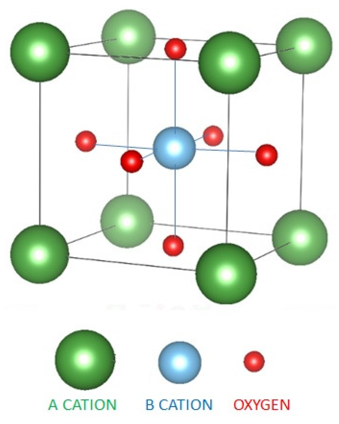
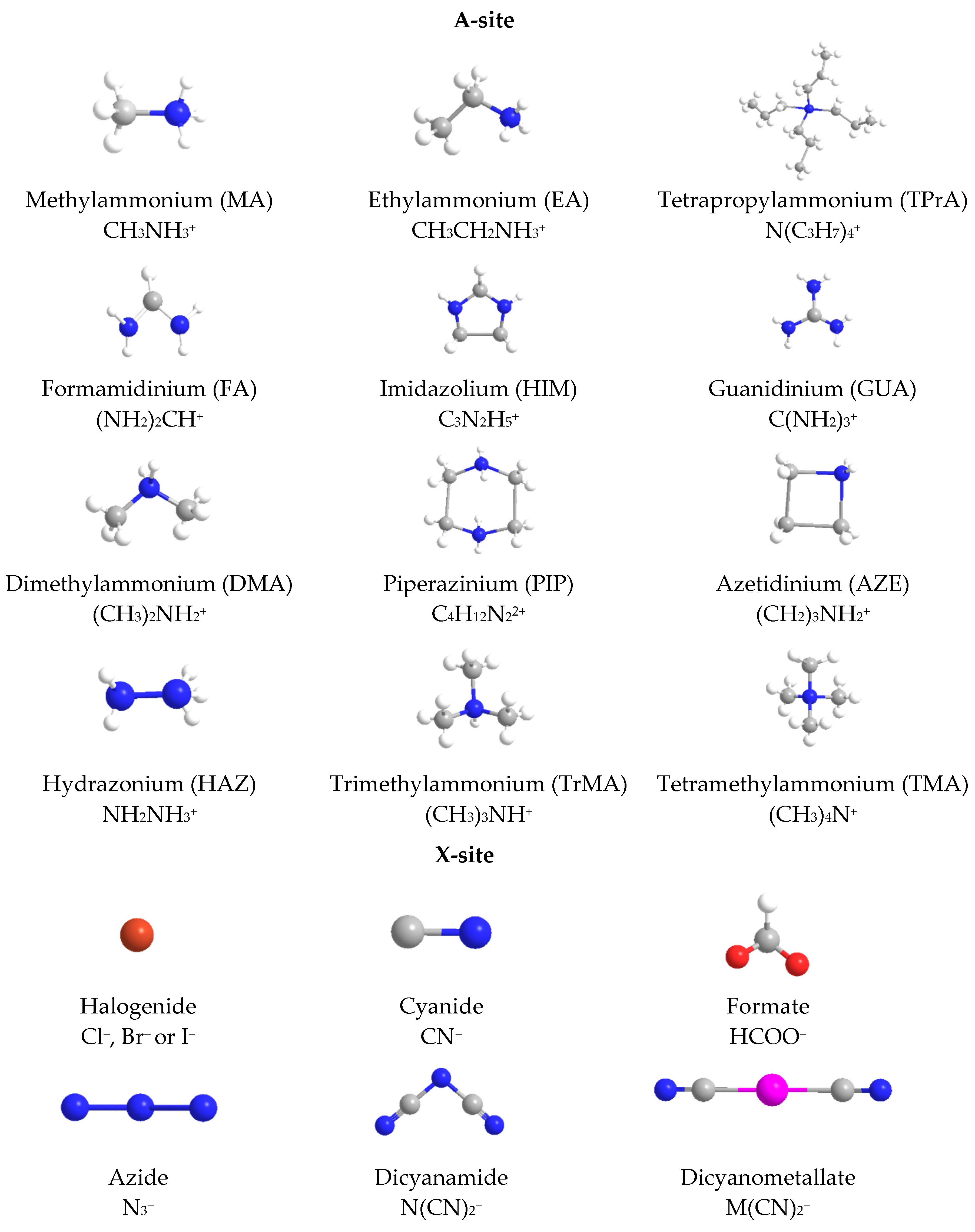
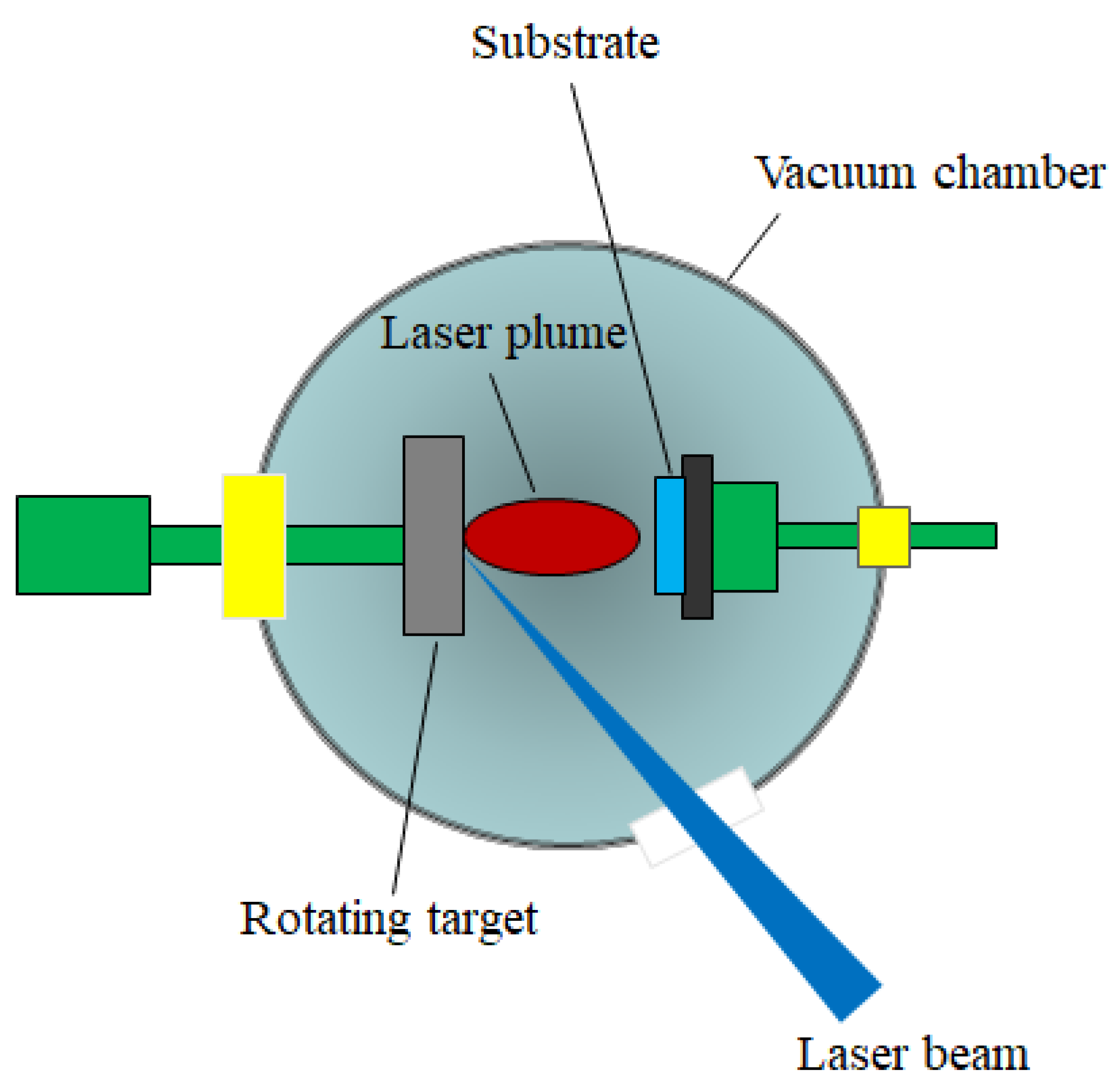
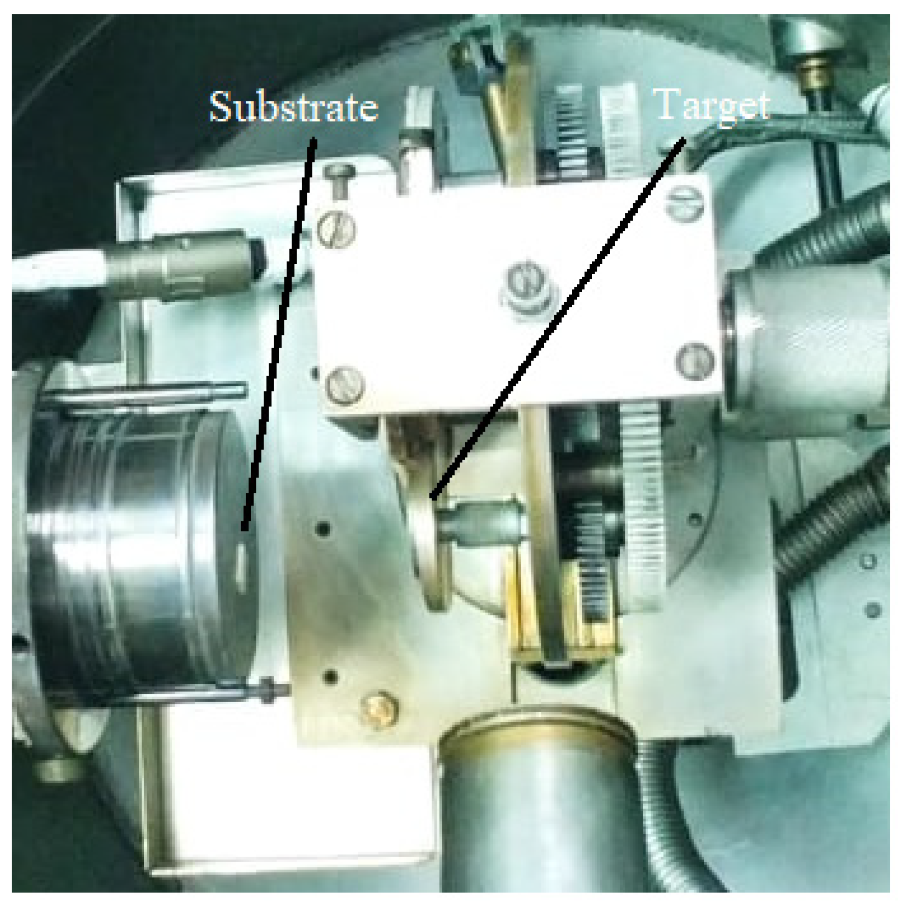
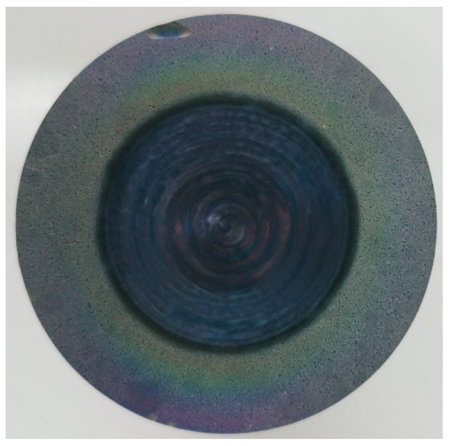
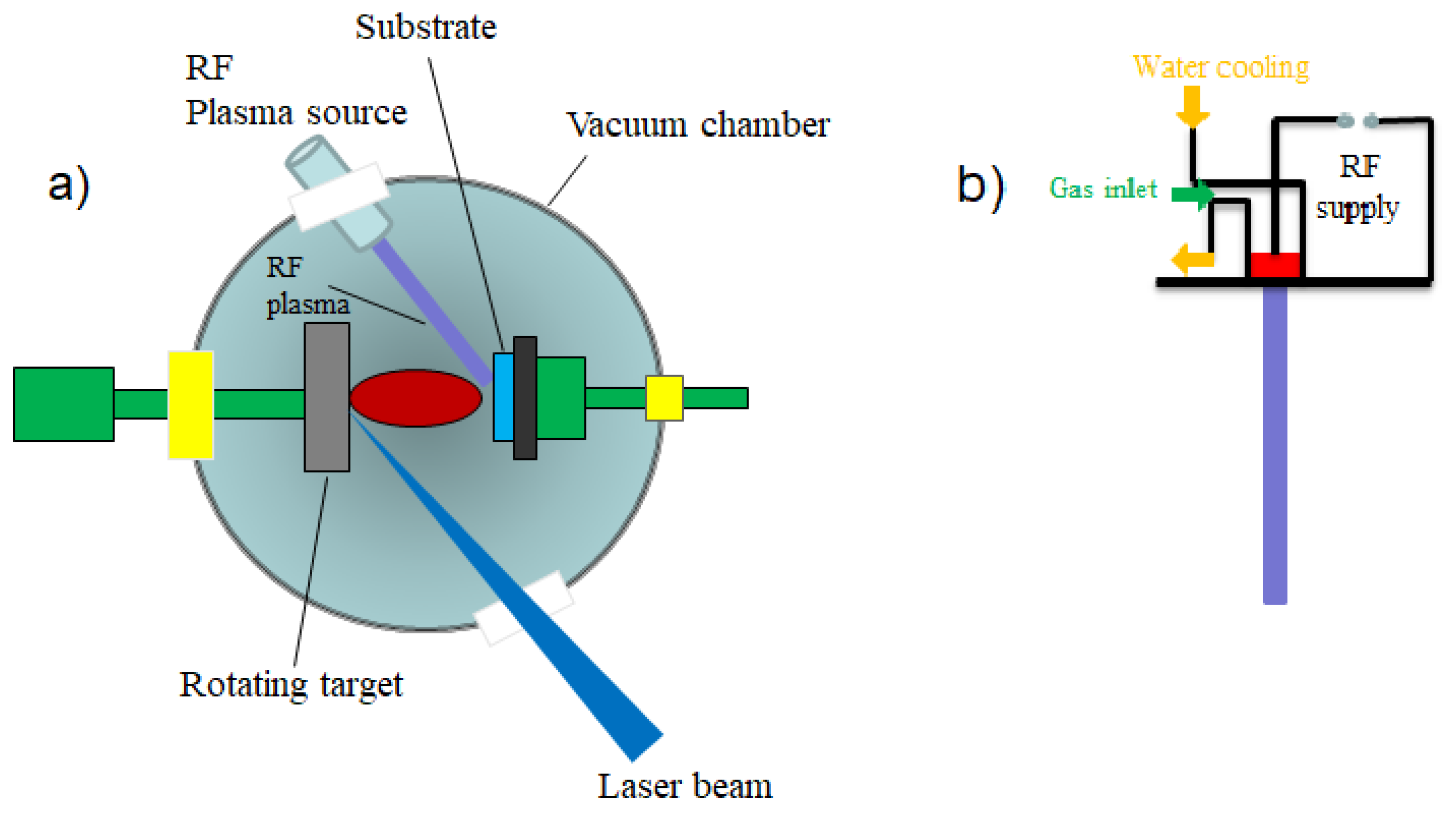
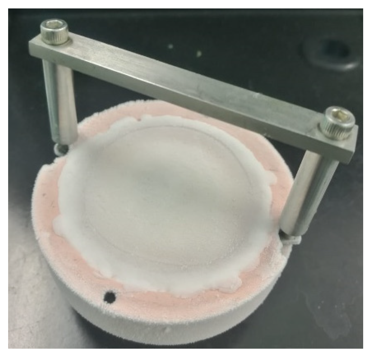
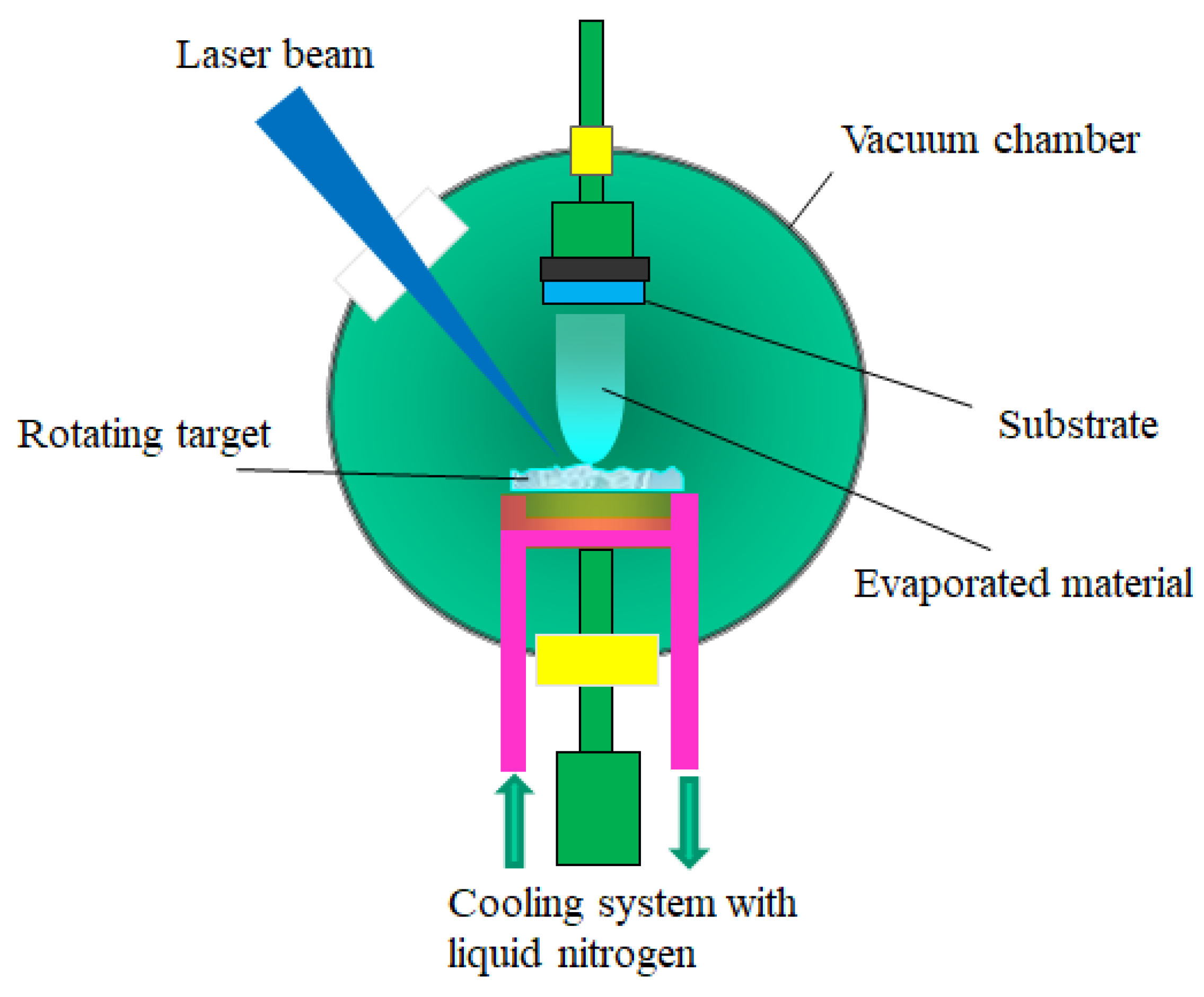
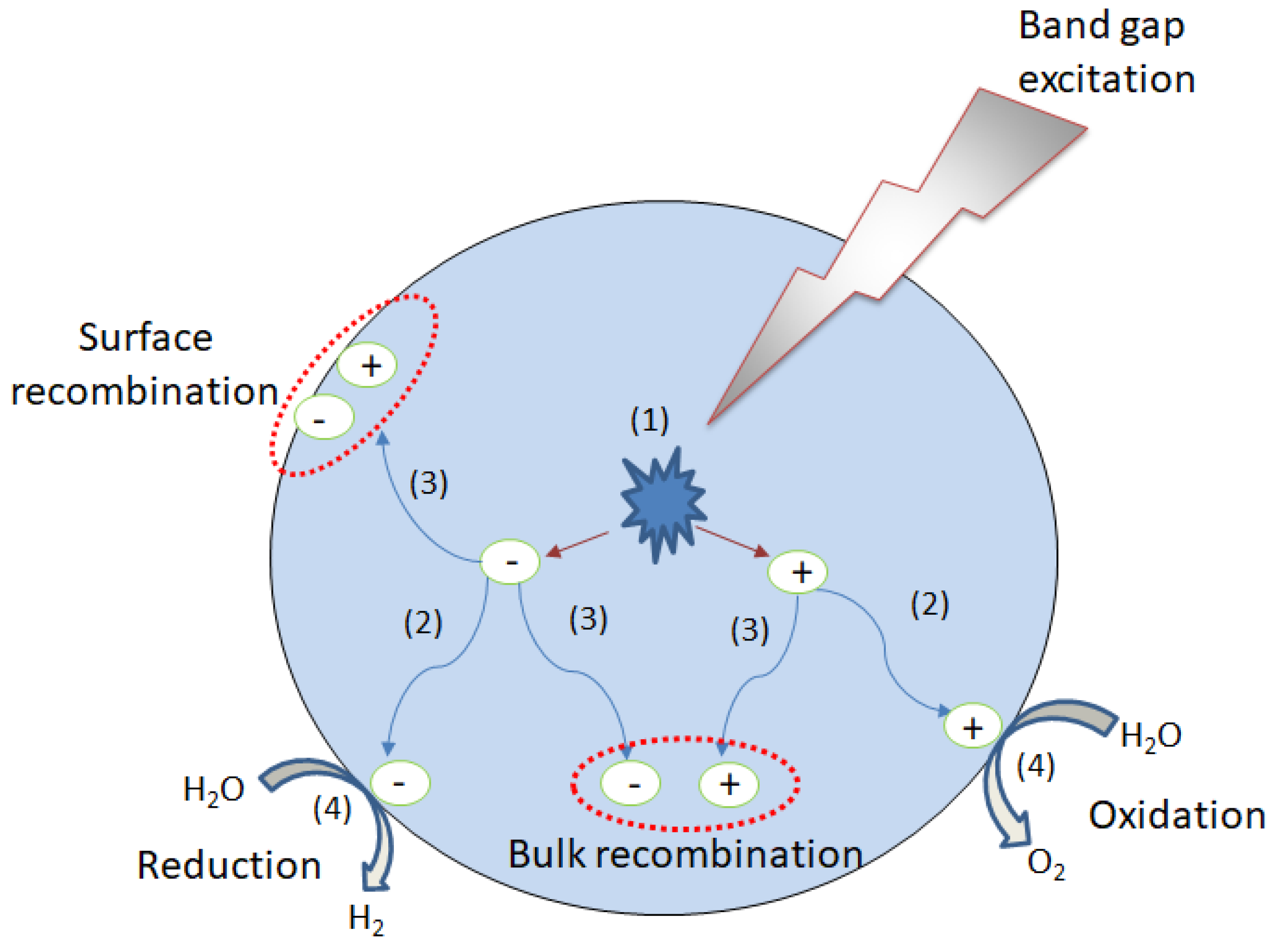
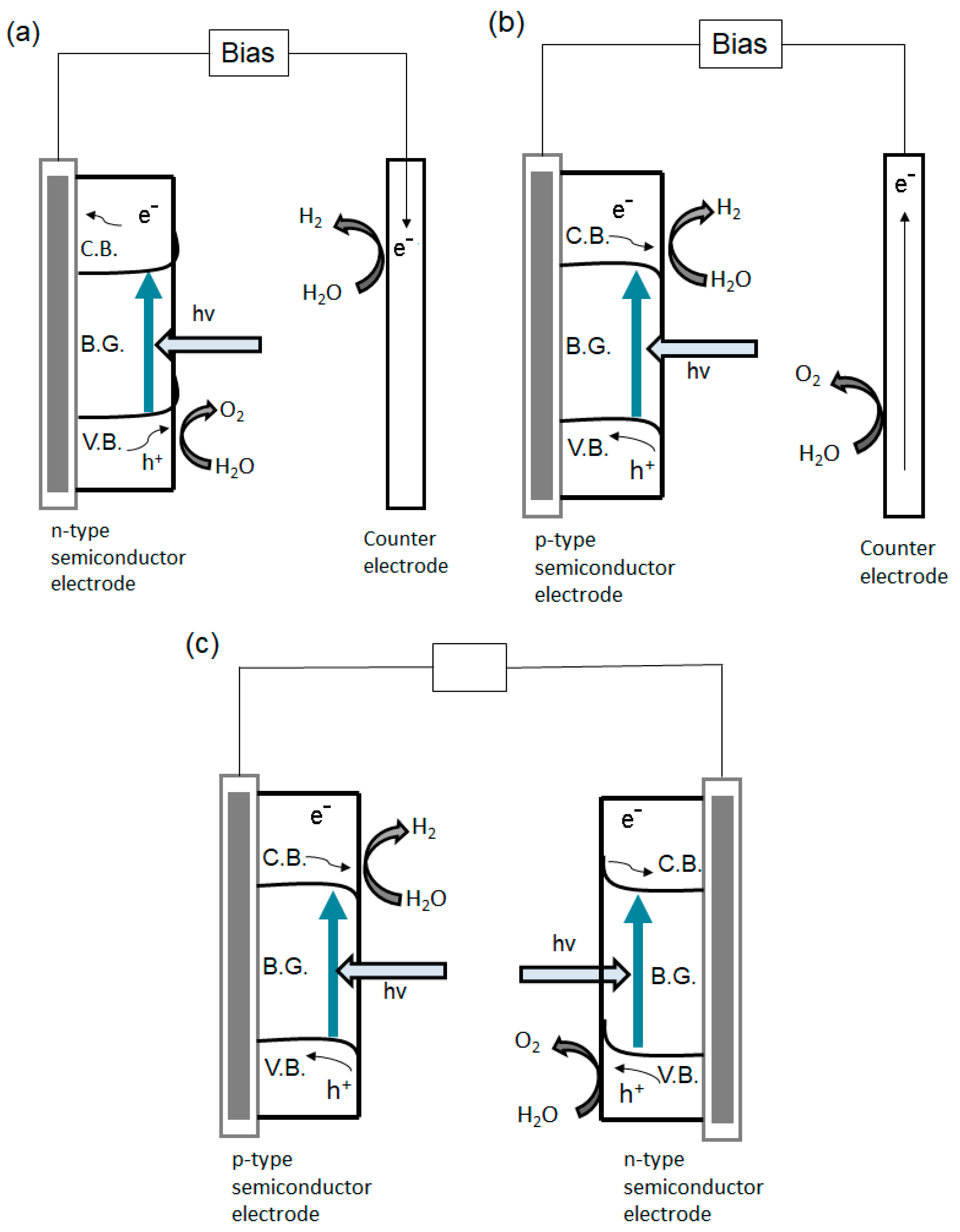
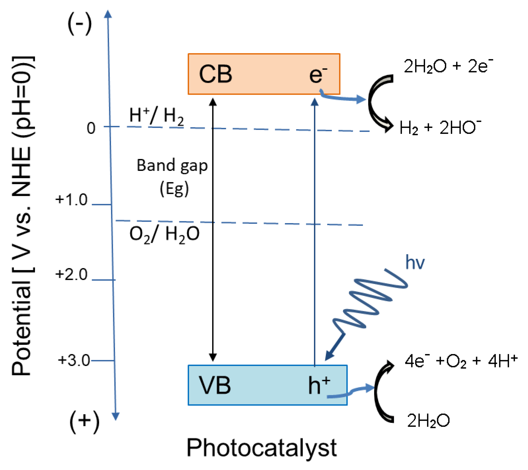
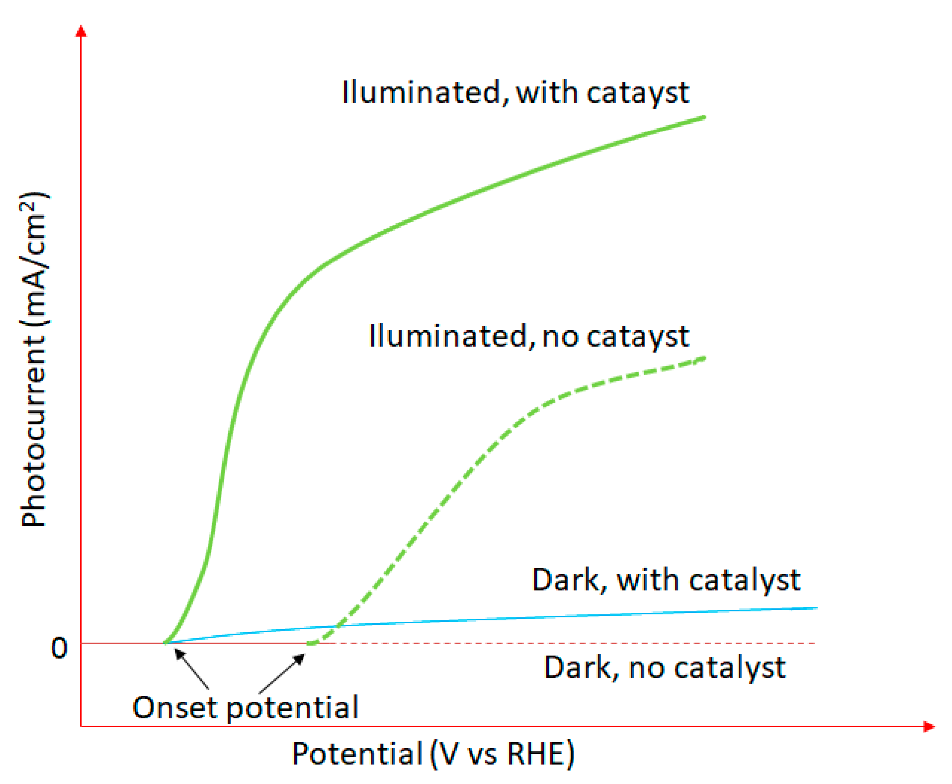
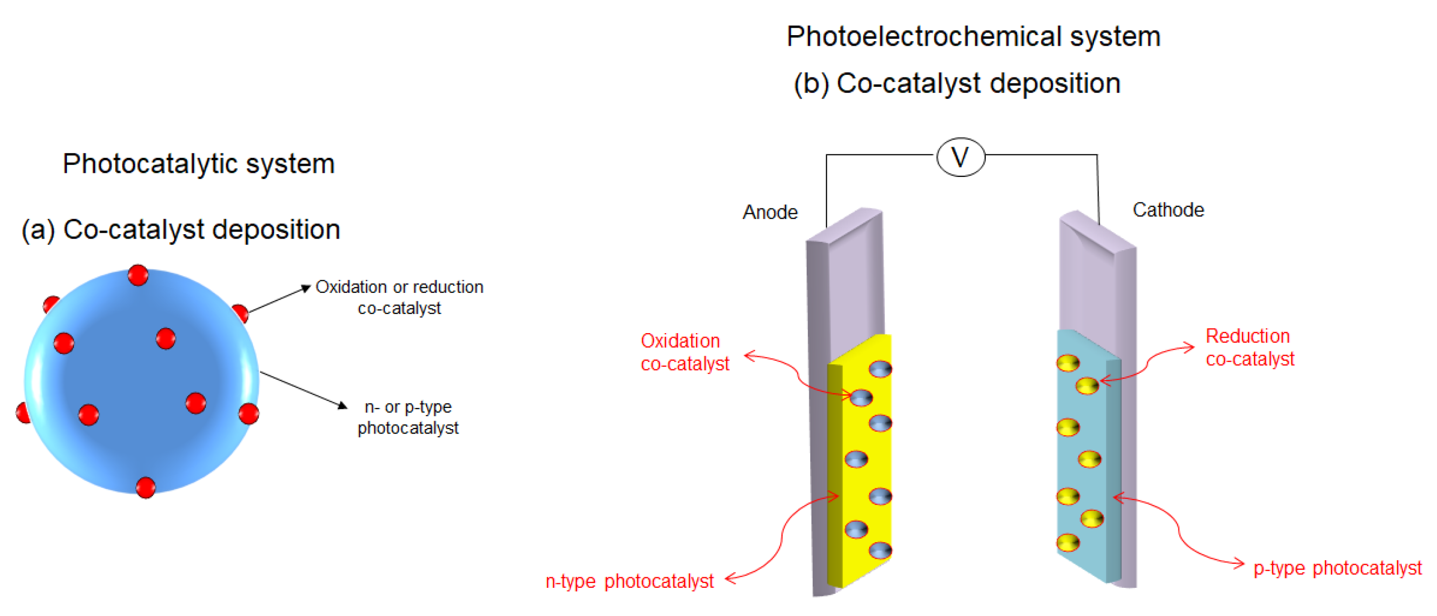
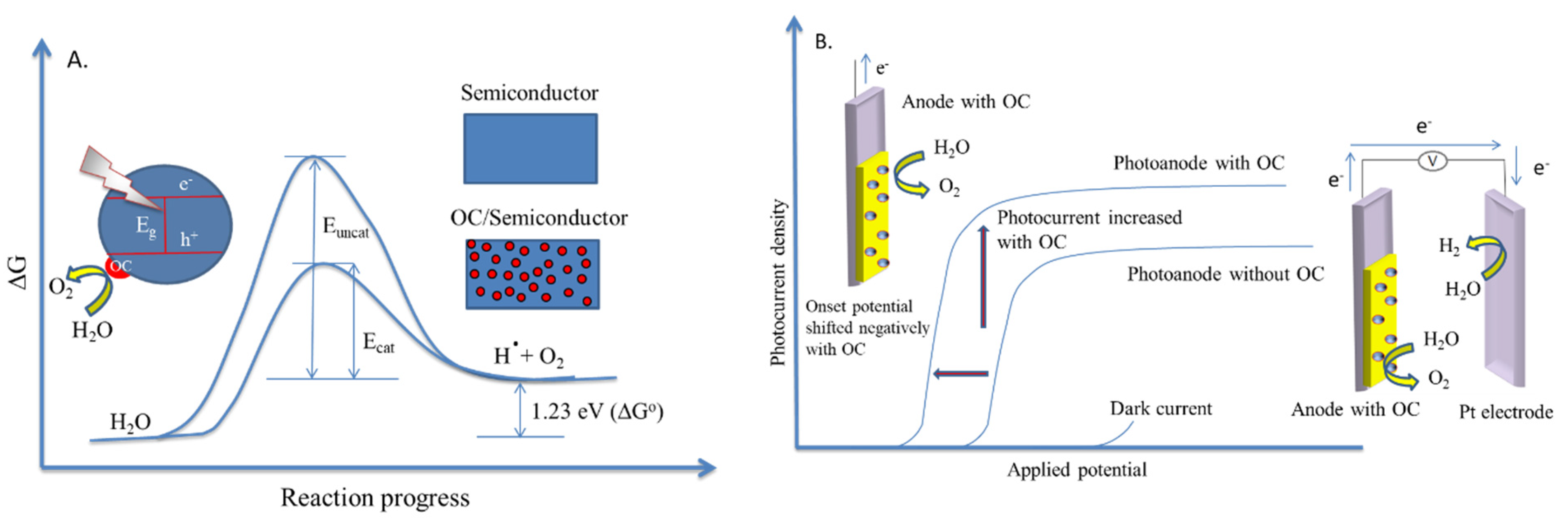
| Catalyst | Preparation Method | SSA (m2/g) | Ref. |
|---|---|---|---|
| BaTiO3 | Solid state reaction | 0.4 | [44] |
| PbTiO3 | 0.5 | ||
| LaAlO3 | Citrate | 4.0 | [55] |
| LaAl0.95Mn0.05O3 | 8.0 | ||
| LaAl0.9Mn0.1O3 | 7.0 | ||
| LaAl0.8Mn0.2O3 | 25.0 | ||
| LaAl0.6Mn0.4O3 | 25.0 | ||
| LaAl0.4Mn0.6O3 | 26.0 | ||
| LaAl0.2Mn0.8O3 | 33.0 | ||
| LaCrO3 | Solid state reaction | 1.9 | [45] |
| LaCrO3 and | Citrate | ~5–7 | [47] |
| LaCr1-xMgxO3 with 0.1 ≤ x ≤ 0.5 | |||
| LaCr0.5Mg0.5O3 | Citrate | 6.08 | [48] |
| LaCr0.5Mg0.5O3∙2MgO | 13.6 | ||
| LaCr0.5Mg0.5O3∙6MgO | 24.2 | ||
| LaCr0.5Mg0.5O3∙17MgO | 36.9 | ||
| LaNiO3 | Solid state reaction | 4.8 | [45] |
| LaNiO3 | Plasmochemical | 17.0 | [51] |
| La0.87Sr0.13Mn0.2Ni0.8O3-x | Freeze drying | 12.7 | [52] |
| La0.4Sr0.6Mo0.1Ni0.9O3 (microstructured) | Freeze drying | 10.3 | [53] |
| La0.4Sr0.6Mn0.4Ni0.6O3 (microstructured) | Freeze drying | 15.9 | [53] |
| LaCuO3 | Solid state reaction | 0.6 | [45] |
| LaMn0.8Cu0.2O3 | Citrate | 19.0 | [50] |
| LaMn0.6Cu0.4O3 | Citrate | 14.0 | [50] |
| LaFe0.84Cu0.16O3 | Citrate | 4.0 | [49] |
| LaCo0.8Cu0.2O3 | Citrate | 21.0 | [38] |
| LaCo0.6Cu0.4O3 | Citrate | 13.0 | [38] |
| (Dy-Y)NiO3 | Mechanochemical | 9.5 | [51] |
| Catalyst | Preparation Method | SSA (m2/g) | Ref. |
|---|---|---|---|
| LaCoO3 | Co-precipitation | 3.5 | [56] |
| LaCoO3 | Co-precipitation | 8.0 | [57] |
| LaCoO3 | Solid state reaction | 3.0 | [45] |
| LaCoO3 | Citrate | 11.3 | [58] |
| LaCoO3 | Citrate | 6.0 | [59] |
| LaCoO3 | Citrate | 15.0 | [50] |
| LaCoO3 | Combustion | 5.7 | [63] |
| LaCoO3 | Ultrasound spray combustion | 5.5 | [64] |
| LaCoO3 | Flame-pyrolysis | 43.0 | [61] |
| LaCoO3+x | Flame-hydrolysis | 15.6–22.8 | [65] |
| La0.8Ca0.2CoO3 | Solid state reaction | 2.0 | [45] |
| La0.9Sr0.1CoO3 | Flame-pyrolysis | 52.0 | [61] |
| La0.8Sr0.2CoO3 | Solid state reaction | 4.7 | [45] |
| La0.8Sr0.2CoO3 a | Freeze-drying | 16.5 | [53] |
| La0.66Sr0.34CoO3 a | 17.4 | ||
| La0.6Sr0.4CoO3 | Solid state reaction | 3.6 | [45] |
| La0.8Ba0.2CoO3 | 5.1 | ||
| La0.53Sr0.47Fe0.2Co0.8O3 a | Freeze-drying | 13.4 | [53] |
| La0.4Sr0.6Fe0.4Co0.6O3 a | 10.4 | ||
| La0.55Sr0.45Mn0.1Ni0.3Co0.6O3 a | 15.0 | ||
| La0.5Sr0.5Fe0.04Ni0.1Co0.86O3 a | 19.6 | ||
| La0.55Sr0.45Fe0.05Ni0.3Co0.65O3 a | 15.2 | ||
| La0.66Sr0.34Ni0.3Co0.7O3 a | 18.8 | ||
| La0.7Sr0.3Ni0.3Co0.7O3 a | 22.7 | ||
| La0.95Ce0.05CoO3 | Citrate | 8.7 | [58] |
| La0.9Ce0.1CoO3 | 10.0 | ||
| La0.9Ce0.1CoO3 | Flame-pyrolysis | 62.0 | [61] |
| La0.8Ce0.2CoO3 | Solid state reaction | 3.1 | [45] |
| La0.8Ce0.2CoO3 | Citrate | 14.2 | [58] |
| La0.7Ce0.3CoO3 | 14.3 | ||
| La0.6Ce0.4CoO3 | 11.6 | ||
| La0.5Ce0.5CoO3 | 18.0 | ||
| PrCoO3 | Co-precipitation | 5.1 | [56] |
| NdCoO3 | 1.6 | ||
| GdCoO3 | 2.1 |
| Catalyst | Preparation Method | SSA (m2/g) | Ref. |
|---|---|---|---|
| LaMnO3 | Co-precipitation | ~15.0 | [3] |
| LaMnO3+x | Co-precipitation | 8.0 | [69] |
| LaMnO3 | Co-precipitation | 7.0 | [57] |
| LaMnO3 | Co-precipitation | 11.0 | [70] |
| LaMnO3 | Solid state reaction | 4.0 | [45] |
| LaMnO3 | Citrate | 5.6 | [49] |
| LaMnO3 | Citrate | 20.0 | [71] |
| LaMnO3 | Citrate | 20.0 | [72] |
| LaMnO3 | Citrate | 22.0 | [55] |
| LaMnO3 | Citrate | 68.0 | [66] |
| LaMnO3 | Citrate | 22.0 | [50] |
| LaMnO3+x | Flame-hydrolysis | 15.6–22.8 | [65] |
| LaMnO3 | Flame-pyrolysis | 56.0 | [61] |
| LaMnO3 | Ultrasound spray combustion | 21.8 | [64] |
| La0.8Ca0.2MnO3 | Solid state reaction | 6.7 | [45] |
| La0.9Sr0.1MnO3 | Flame-pyrolysis | 51.0 | [61] |
| La0.8Sr0.2MnO3 | Flame-pyrolysis | 70.0 | [61] |
| La0.8Sr0.2MnO3 | Solid state reaction | 8.6 | [45] |
| La0.8Sr0.2MnO3+x | Co-precipitation | 5.0 | [73] |
| La0.6Sr0.4MnO3 | Citrate | 18.7 | [71] |
| La0.6Sr0.4MnO3 | Solid state reaction | 3.3 | [45] |
| La0.6Sr0.4MnO3 a | Citrate | 4.32 | [74] |
| SrTi0.8Zr0.1Mn0.1O3 | Co-precipitation | 15.0 | [75] |
| La(Mn,Pd)O3 (2.9 wt.% Pd) | Citrate method | 12.0 | [67] |
| La(Mn,Pd)O3 (2.32 wt.% Pd) | Flame pyrolysis | 32.0 | [67] |
| La(Mn,Pd)O3 (2.37 wt.% Pd) | Solution combustion | 1.0 | [67] |
| La(Mn,Pd)O3 (2.11 wt.% Pd) | Ultrasonic spray combustion | 39.0 | [67] |
| La0.9Ce0.1MnO3 | Citrate | 32.0 | [71] |
| La0.9Ce0.1MnO3 | Flame-pyrolysis | 84.0 | [61] |
| (La-Ce)MnO3 | Mechanochemical | 19.0 | [51] |
| PrMnO3+x | Co-precipitation | 2.5 | [69] |
| NdMnO3+x | Co-precipitation | 2.4 | [69] |
| NdMnO3 | Citrate | 20.0 | [72] |
| SmMnO3 | 19.0 | ||
| Sm0.9Sr0.1MnO3 | 20.0 | ||
| Sm0.7Sr0.3MnO3 | 14.0 | ||
| Sm0.5Sr0.5MnO3 | 13.0 | ||
| La0.9Eu0.1MnO3 | Citrate | 26.4 | [71] |
| GdMnO3+x | Co-precipitation | 5.3 | [69] |
| (Dy-Y)MnO3 | Mechanochemical | 14.0 | [51] |
| Catalyst | Preparation Method | SSA (m2/g) | Ref. |
|---|---|---|---|
| LaFeO3 | Co-precipitation | 10.0 | [57] |
| LaFeO3 | Co-precipitation | 5.5 | [3] |
| LaFeO3+x | Co-precipitation | 3.5 | [69] |
| LaFeO3 | Co-precipitation | 20.9 | [76] |
| LaFeO3 | Solid state reaction | 3.1 | [45] |
| LaFeO3 | Citrate | 2.9 | [77] |
| LaFeO3 | Citrate | 3.0 | [78] |
| LaFeO3 | Citrate | 19.5 | [76] |
| LaFeO3 | Citrate | 21.0 | [79] |
| LaFeO3 | Combustion | 3.0 | [63] |
| LaFeO3+x | Flame-hydrolysis | 15.6 | [65] |
| LaFeO3 | Flame-pyrolysis | 38.0 | [61] |
| LaFeO3 | Ultrasound spray combustion | 9.8 | [64] |
| LaFe0.9Mg0.1O3 | Citrate | 4.3 | [77] |
| LaFe0.8Mg0.2O3 | 5.5 | ||
| LaFe0.7Mg0.3O3 | 7.9 | ||
| LaFe0.6Mg0.4O3 | 9.7 | ||
| LaFe0.5Mg0.5O3 | 5.3 | ||
| La0.9Ca0.1FeO3 | Co-precipitation | 14.0 | [76] |
| La0.9Ca0.1FeO3 | Citrate | 6.0 | [78] |
| La0.9Ca0.1FeO3 | Citrate | 17.8 | [76] |
| La0.9Ca0.1FeO3 | Citrate | 38.0 | [79] |
| La0.8Ca0.2FeO3 | Co-precipitation | 8.3 | [76] |
| La0.8Ca0.2FeO3 | Citrate | 5.0 | [78] |
| La0.8Ca0.2FeO3 | Citrate | 38.6 | [76] |
| La0.8Ca0.2FeO3 | Citrate | 38.0 | [79] |
| La0.7Ca0.3FeO3 | Co-precipitation | 5.4 | [76] |
| La0.7Ca0.3FeO3 | Citrate | 3.0 | [78] |
| La0.7Ca0.3FeO3 | Citrate | 38.6 | [76] |
| La0.7Ca0.3FeO3 | Citrate | 38.0 | [79] |
| La0.6Ca0.4FeO3 | Co-precipitation | 8.3 | [76] |
| La0.6Ca0.4FeO3 | Citrate | 31.2 | [76] |
| La0.6Ca0.4FeO3 | Citrate | 5.0 | [78] |
| La0.6Ca0.4FeO3 | Citrate | 33.0 | [79] |
| La0.5Ca0.5FeO3 | Citrate | 0.7 | [78] |
| La0.8Sr0.2FeO3 | Solid state reaction | 4.7 | [45] |
| La(Fe,Pd)O3 (2.4 wt.% Pd) | Citrate | 14.0 | [67] |
| La(Fe,Pd)O3 (2.28 wt.% Pd) | Flame pyrolysis | 22.0 | |
| La(Fe,Pd)O3 (1.25 wt.% Pd) | Ultrasonic spray combustion | 27.0 | |
| La(Fe,Pd)O3 (2.47 wt.% Pd) | Solution combustion | 1.6 | |
| (La-Ce)FeO3 | Mechanochemical | 5.3 | [51] |
| PrFeO3+x | Co-precipitation | 5.8 | [69] |
| NdFeO3+x | Co-precipitation | 4.5 | [69] |
| NdFeO3 | Citrate | 2.3 | [77] |
| SmFeO3 | Citrate | 4.3 | [77] |
| GdFeO3+x | Co-precipitation | 5.6 | [69] |
| (Dy-Y)FeO3 | Mechanochemical | 8.6 | [51] |
| Catalyst | Support | Morphology of the Support | Preparation Method | SSA (m2/g) | Ref. |
|---|---|---|---|---|---|
| LaMnO3 | foil Fe2Cr20Al5 | monolith | Wet impregnation | 23.3 | [80] |
| LaMnO3 | ZrO2 | powder | Solution combustion method | 132.5 | [82] |
| 30% LaMnO3 | (5%La2O3/Al2O3) | powder | Deposition precipitation | 88.0 | [70] |
| 20% LaMnO3 | MgO | 25.0 | [70] | ||
| La0.8Sr0.2MnO3+x | MgAl2O4 | powder | Wet impregnation | 34.0 | [73] |
| La0.8Sr0.2MnO3+x | NiAl2O4 | 22.0 | |||
| La0.8Sr0.2MnO3+x | CoAl2O4 | 18.0 | |||
| La0.95Ag0.05MnO3 | foil Fe2Cr20Al5 | monolith | Wet impregnation | 27.4 | [80] |
| La0.9Ag0.1MnO3 | 30.9 | ||||
| La0.8Ag0.2MnO3 | 29.4 | ||||
| La0.7Ag0.3MnO3 | 31.5 | ||||
| LaFeO3 | FeCr(20%)Al(5%) | monolith | Citrate method | 7.7 | [81] |
| La0.66Sr0.34Ni0.29Co0.69Mn0.02O3(20%) | (47% Al2O3–52% SiO2) | fiber | Freeze-drying | 18.0 | [83] |
| La0.66Sr0.34Ni0.29Co0.69Mn0.02O3(15%) | (47% Al2O3–52% SiO2) | 23.0 | |||
| La0.66Sr0.34Ni0.29Co0.69Fe0.02O3 (27%) | (95% Al2O3–5% SiO2) | 27.0 | |||
| La0.66Sr0.34Ni0.29Co0.69Fe0.02O3 (14%) | (95% Al2O3–5% SiO2) | 22.0 | |||
| La0.66Sr0.34Ni0.29Co0.69Fe0.02O3(15%) | (47% Al2O3–52% SiO2) | 24.0 | |||
| La0.66Sr0.34Ni0.29Co0.69Fe0.02O3(12%) | (47% Al2O3–52% SiO2) | 27.0 |
| Perovskite | Support | λ (nm)/ν (Hz) | Fluence (J/cm2) | PO2 a (mBar) | T b (°C) | Film Thickness (nm) | Ref. |
|---|---|---|---|---|---|---|---|
| BaTiO3 | MgO (001) | 248/10 | 2–4 | 4 × 10⁻³ | 1000 | 115 | [88,89] |
| BaTiO3 | SrTiO3 (001) | 248/10 | 2–4 | 3 × 10⁻¹ | 800 | 115 | [88,89] |
| BaTiO3 | SrTiO3 (001) | 248/10 | 2–4 | 2 × 10⁻³ | 800 | 220 | [88,89] |
| SrTiO3 | LaAlO3 (100) | 248/5 | 1.3 | 1.7 × 10⁻⁴ | 660 | - | [90] |
| BaZrO3 | Si | 193/1–3 | 5.2 | 0.2 | 605 | 1–53 | [91] |
| BaZrO3 | SrTiO3 (100) | 193/1–3 | 5.2 | 0.2 | 650 | 1–53 | [91] |
| Y1-xSrxMnO3 (x = 1, 0.9, 0.8, 0.7) | SrTiO3 (100) | 248/3 | 2 | 0.01–0.13 | 800 | 0.6–0.65 | [92] |
| Y1-xSrxMnO3 (x = 1, 0.9, 0.8, 0.7) | LaAlO3 (100) | 248/3 | 2 | 0.01–0.13 | 800 | 0.6–0.65 | [92] |
| Y1-xSrxMnO3 (x = 1, 0.9, 0.8, 0.7) | NdGaO3 (101) | 248/3 | 2 | 0.01–0.13 | 800 | 0.6–0.65 | [92] |
| La0.67Ca0.33MnO3 | LaAlO3 | -/5 | n.s. d | 0.26 | 500–700 | 100 | [93] |
| La0.67Ca0.33MnO3 RF c | LaAlO3 (100) | n.s. | n.s. | Pressure of 0.053 (60:40 = Ar:O2 or pure Ar) | 850 | n.s. | [93] |
| La0.67Ca0.33MnO3 RF c | NdGaO3 (110) | n.s. | n.s. | Presure of 0.053 (60:40 = Ar:O2 or pure Ar) | 850 | n.s. | [93] |
| La0.67Ca0.33MnO3 | NdGaO3 | 248/8 | 0.2–0.25 | 0.13 | 600–800 | 85 | [94] |
| La0.67Ca0.33MnO3 RF c | SrTiO3 (100) | n.s. | n.s. | Presure of 0.053 (60:40 = Ar:O2 or pure Ar) | 850 | n.s. | [93] |
| SrFeO3 | SrTiO3 (111) | 248/2 | 2.3 | 0.13 | 700 | n.s. | [95] |
| SrTi1−xFexO3−y (x = 0.2–0.5) | Sapphire (Al2O3) | 248/8 | 1.5 | 0.13 | 700 | 200–300 | [96] |
| LaNiO3 | SrTiO3 (100) | 248/5 | 2 | 0.4 | 825 | 100 | [97] |
| LaNiO3 | LaAlO3 (100) | 248/5 | 1.3 | 0.35 | 660 | n.s. | [90] |
| Y(Ni0.5Mn0.5)O3 | SrTiO3 (001) | 248/2 | 1.5 | 0.6 | 550–850 | 70 | [98] |
| Y(Ni0.5Mn0.5)O3 | SrTiO3 (110) | 248/2–20 | 2 | 0.6 | 550–850 | 70 | [98] |
| Y(Ni0.5Mn0.5)O3 | SrTiO3 (111) | 248/2–20 | 2 | 0.6 | 550–850 | 70 | [98] |
| Ca0.25Cu0.75TiO3 | SrTiO3 (100) | 248/10 | 3 | 0.16 | 600–800 | 250 | [99] |
| SrRuO3 | SrTiO3 (100) | 193/1–3 | 5.2 | 0.2 | 590–650 | n.s. | [91] |
| SrRuO3 | SrTiO3 (111) | 248 | 2.3 | 0.13 | 700 | n.s. | [95] |
| PbTiO3 | Si (100) | 248/5 | 8 | 0.13–0.2 | 530 | 530 | [100] |
| PbZr0.2Ti0.8 O3 | SrRuO3/SrTiO3 (100) | 193/1–3 | 5.2 | 0.2 | 587 | n.s. | [91] |
| Pb(Zr0.45Ti0.55)O3 | Pb(Zr0.45Ti0.55)O3/Pt/Ti/SiO2/Si prepared by citrate method | 248/10 | 1.2 | 1.3 × 10⁻⁴ | RT e | 600 | [101] |
| BiFeO3 | Pt/TiO2/SiO2/Si | 355/2.5 | n.s. | 0.07 | 450 | 300 | [102,103] |
| BiFeO3 | SrTiO3 (001) | 355/2.5 | n.s. | 0.01 | 580 | 70 | [102,103] |
| BiFeO3 | Pt(111)/TiO2/SiO2/Si(100) | 248/5 | 2.5 | n.s. | 450 | 230 | [104] |
| BiFeO3 | SrTiO3 (100) | 248/5 | 2 | 0.07 | 750 | 400 | [105] |
| BiFeO3 | SrRuO3/SrTiO3 | 248 | n.s. | 0.07 | 550–800 | 280–300 | [106] |
| BiFeO3 | Nb-doped SrTiO3 (100) | n.s. | n.s. | 0.14 | 650 | 106.5 | [107,108] |
| BiFeO3 | SrTiO3 (100) | n.s. | n.s. | 0.14 | 650 | 54.3 | [107,108] |
| BiFeO3 | DyScO3 (110) | n.s. | n.s. | 0.14 | 650 | 34.1 | [107,108] |
| BiFeO3 | Nb-doped SrTiO3 (100) | 248/5 | n.s. | 0.04–0.4 | 670 | 30–80 | [109] |
| BiFeO3 | Pt/TiO2/SiO2/Si | 248/10 | 2.5 | n.s. | RT e | 150 | [110] |
| BiFeO3 | Nb-doped SrTiO3 (100) | 248 | n.s. | 0.02 | 500 | 10 | [111] |
| BiFeO3 | SrRuO3/SrTiO3 (001) | 248 | n.s. | 0.01–0.26 | 650–750 | n.s. | [112] |
| BiFeO3 | Si (100) | 248/5 | n.s. | n.s. | 670 | 50–100 | [113] |
| BiFeO3 | Pt/TiO2/SiO2/Si | 248/3 | 1.5 | 0.53 | 625 | 100 | [114,115] |
| BiFeO3 | SrRuO3/SrTiO3 (111) | 248/3 | 1.5 | 0.53 | 625 | 100 | [114,115] |
| BiFeO3 | Pt coated Al2O3 | 248/3 | 1.5 | 0.53 | 625 | 100 | [114,115] |
| (1-x)BiFeO3-xPbTiO3 | PbTiO3/Pt/Ti/SiO2/Si | 248/5 | 2.5 | 0.2 | 550 | 230 | [116] |
| (1-x)BiFeO3-xPbTiO3 (x = 0.7, 0.8, 0.9) | Pt/Ti/SiO2 | 248/5 | 6 | 0.2 | 545 | 400 | [117] |
| LaCo1-xCrxO3 | LaAlO3 (100) | 248/15 | n.s. | 0.083 | 650 | 450–530 | [118] |
| LaMnO3 | SrTiO3 (001) | n.s. | n.s. | 0.013 | 700 | 30 | [119] |
| LaMnO3 | LaAlO3 (001) | 248/2 | n.s. | 0.01 | 700 | 14–90 | [120] |
| La0.8Ca0.2MnO3 | LaAlO3 (100) | 248/5 | 3.2 | 0.4 | 800 | 200 | [121] |
| La0.7Sr0.3MnO3 | Si (100) | 248/10 | n.s. | 0.27 | 650 | 200 | [122] |
| La0.67Sr0.33MnO3 | LaAlO3 | 308/5 | 2 | 0.27 | 500–800 | 130 | [123] |
| La0.67Sr0.33MnO3 | SrTiO3 | 308/5 | 2 | 0.27 | 500–800 | 130 | [123] |
| LaFeO3 | SrTiO3 (100) | 248/4 | 1.9 | 0.4 | 670 | 25–35 | [124] |
| LaFeO3 | GdScO3 (110) | 248 | 1 | 0.13 | 700 | 100 | [125] |
| LaFeO3 | SrTiO3 (100) | 248/4 | 2.4 | 0.2 | 670 | 54 | [126] |
| LaFeO3 | SrTiO3 (100) | 248/5 | 5.5 | 0.07 | 800 | 400 | [127] |
| LaFeO3 | Nb-doped SrTiO3 | 193/5 | 2.2 | 0.05–0.9 | 750 | n.s. | [128] |
| LaFeO3 | SrTiO3 (100) | 248/10 | 0.2 | 4 × 10⁻⁵ | 700 | 65 | [129] |
| LaFeO3 | LaAlO3 (100) | 248/10 | 0.2 | 4 × 10⁻⁵ | 700 | 65 | [129] |
| La1-xSrxCoO3 | Si (001) | 266/10 | 2 | 0.05 | 740 | 120 | [130] |
| La1-xSrxCoO3 | MgO (001) | 266/10 | 2 | 0.05 | 740 | 120 | [130] |
| La1-xSrxCoO3 (x = 0, 0.1, 0.2) | Si (100) | 248/10 | 2 | 0.13 | 600 | n.s. | [131] |
| La1-xSrxCoO3 (x = 0, 0.1, 0.2) | Si (100) | 266/10 | 2 | 0.05 | 660 | 100 | [132] |
| Sr1-xLaxRu1-xFexO3 (x = 0.05, 0.1, 0.2, 0.3) | SrTiO3 (100) | 248/4 | 2.5 | 0.2–0.33 | 750 | 60 | [133] |
| Bi0.9La0.1Fe0.95Mn0.05O3 | Pt (111)/Ti/SiO2/Si | 248 | 1.5 | 7 × 10⁻³ | 450–650 | 250 | [134] |
| (Bi1-xLax)(Fe1-xAlx)O3 (x = 0, 0.1, 0.2, 0.3, 0.4) | Nb-doped SrTiO3 (001) | 266 | n.s. | 0.065 | 600 | n.s. | [135] |
| La0.8Ce0.2MnO3 | LaAlO3 (001) | 248/8 | 2 | 0.4 | 800 | 150 | [136] |
| Bi1-xPrxFeO3 (x = 0, 0.05, 0.1, 0.15) | Pt/SiO2 | 355/5 | 2.5 | n.s. | 450 | 200 | [137] |
| NdNiO3 | MgO (100) | 248/10 | 1.5 | 0.15 | 675 | 500 | [138] |
| NdNiO3 | SrTiO3 (100) | 248/10 | 1.5 | 0.15 | 675 | 500 | [138] |
| NdNiO3 | NdGaO3 (110) | 248/10 | 1.5 | 0.15 | 675 | 500 | [138] |
| NdNiO3 | NdGaO3 (001) | -/10 | 1.9 | 3 | 900 | 30–50 | [139] |
| Bi0.9Sm0.1Fe0.95Co0.05O3 | Pt/TiO2/SiO2/Si | 248/10 | 2–5 | 0.13 | 700–750 | 300–360 | [140] |
| Bi0.9Sm0.1Fe0.95Co0.05O3 | Pt/TiO2/SiO2/Si | 248/10 | 2–5 | 0.13 | 700–750 | 300–360 | [140] |
| Bi1-xSmxFeO3 (x = 0.05, 0.1, 0.12, 0.14, 0.16) | Pt (111)/SiO2 | 355/5 | n.s. | 0.04 | 450 | 200 | [141] |
| TmMnO3 | SrTiO3 (110) | 248 | n.s. | 0.1 | 940 | 20 | [142] |
| Material | Target Concentration | Substrate | λ (nm)/ ν (Hz) | Fluence (J/cm2) | PN2 (mbar) | DT-S (cm) | Ref. |
|---|---|---|---|---|---|---|---|
| rGO/BiFeO3 | 3 wt.% BiFeO3 5 wt.% GO | F-doped SnO2 | 266/10 | 0.4 | 0.2 | 4 | [148] |
| rGO/LaFeO3 | 3 wt.% LaFeO3 5 wt.% GO | F-doped SnO2 | 266/10 | 0.4 | 0.2 | 4 | [148] |
| CH3NH3PbI3 | PbI2:MAI = 1:3 | ITO | IR/2 | 0.125–0.135 | 1 × 10⁻³ | 7 | [149] |
| CH3NH3PbI3 | PbI2:MAI = 1:1 in DMSO and MEG | FTO/NiOx | - | - | - | - | [150] |
| Material | Electrode Type | Eg a (eV) | Electrolyte/Light Source/Intensity (mW/cm2) | Performance | Stability | Ref. |
|---|---|---|---|---|---|---|
| BaTiO3 | Photo-anode | 3.11 | 0.1 M NaOH (pH = 13)/Xe arc UV-Vis lamp/180 | 0.5 VSCE: Jph ≈ 0.07 mA/cm2; | n.s.b | [188] |
| PbTiO3-TiO2 | Photo-anode | 2.78–3.6 | 0.1 M KOH/Xe lamp Vis light | 1.23 VRHE: Jph ≈ 0.3 mA/cm2 IPCEc ≈ 70% at 380 nm IPCE ≈ 38% at 420 nm IPCE < 1% at 500 nm Onset potential 0.3 VRHE | Stable after 300 s | [189] |
| SrTiO3 nanocubes | Photo-anode | 3.43 | 0.1 Na2SO4 (pH = 7)/AM1.5/100 | 0 VAg/AgCl: Jph ≈ 0.5 uA/cm2 0.9 VAg/AgCl: Jph ≈ 4 uA/cm2; 60 μmol/h O2 | n.s. | [190] |
| SrTiO3 | Photo-anode | 3.4 | 0.1 M Na2SO4/AM1.5/100 | 0 VAg/AgCl: Jph ≈ 50 μA/cm2 1.5 VAg/AgCl: Jph ≈ 0.5 mA/cm2 IPCE ≈ 10% at 350 nm IPCE < 1% for λ > 400 nm | n.s. | [191] |
| SrTiO3—carbon quantum dots | Photo-anode | n.s. | 0.1 M Na2SO4/AM1.5/100 | 0 VAg/AgCl: Jph ≈ 110 μA/cm2 1.5 VAg/AgCl: Jph ≈ 1.7 mA/cm2 IPCE ≈ 14% at 350 nm IPCE ≈ 1% at 860 nm | n.s. | [192] |
| BiFeO3 | Photo-anode | 2.1 | 0.2 M Na2SO4/sunlight 300 W Xenon lamp | 0.8 VAg/AgCl: Jph ≈ 0.12 μA/cm2 | Stable after 400 s | [201] |
| H2 treated BiFeO3 | Photo-anode | 2.0 | 0.2 M Na2SO4/sunlight, 300 W Xenon lamp | 0.8 VAg/AgCl: Jph ≈ 0.69 μA/cm2 | Stable after 400 s | [201] |
| BiFeO3 | Photo-anode | 2.4 | 0.2 M Na2SO4 (pH = 6.5)/AM1.5/100 | 1 VAg/AgCl: Jph≈ 0.17 mA/cm2 IPCE≈ 17% at 420 nm Onset potential 0.1 VAg/AgCl | n.s. | [202] |
| Ni-B/BiFeO3 | Photo-anode | n.s. | 0.1 M potassium borate (pH = 9.2) | 1 VAg/AgCl: Jph ≈ 0.72 mA/cm2 | Stable after 3 h | [202] |
| BFO/SrRuO3 | Photo-anode | 2.74 | 1M Na2SO4/250 mW/cm2 | 0.64 VAg/AgCl: Jph ≈ 10 μA/cm2 Onset potential 0.18 VAg/AgCl | n.s. | [221] |
| Ti-doped BiFeO3 | Photo-anode | 1.97 | 1 M NaOH/300W UV Xe lamp | 1.23 VRHE: Jph ≈ 0.04mA/cm2 Onset potential 0.81 VRHE | Stable after 3600 s | [208] |
| Y-doped BiFeO3 | Photo-anode | n.s. | 0.5 M NaOH (pH = 13)/laser diode 405 nm (5 mW) | 1.4 VRHE: Jph = 0.72 mA/cm2 | Stable after 900 s | [209] |
| BiFeO3/TiO2/FTO | Photo-anode | n.s. | 1M NaOH/300 W Xenon lamp Vis light | 1.5 VSCE: Jph ≈ 15 mA/cm2 Onset potential ≈ 0.6 VSCE | Stable after 300 s | [222] |
| BiFeO3/TiO2/FTO | Photo-anode | n.s. | 1M NaOH/AM1.5/100 | 1.5 VSCE: Jph ≈ 17 mA/cm2 Onset potential ≈ 0.6 VSCE | Stable after 300 s | [222] |
| WO3/BiVO4/BiFeO3 | Photo-anode | n.s. | 0.5M Na2SO4/AM1.5/100 | 2.53 VRHE: Jph = 46.9 mA/cm2 | Stable after 200 s | [212] |
| LaFeO3 | Photo-cathode | 2.16 | 0.1 M NaOH (pH = 13)/AM1.5/100 | 0.73 VRHE: Jph = −0.1 mA/cm2 | Stable after 1 h | [223] |
| LaFeO3 | Photo-cathode | 2.16 | 0.1 M NaOH (pH = 13)/AM1.5/100 | 0.5 VRHE: Jph ≈ −0.2 mA/cm2 | Stable after 1 h | [223] |
| LaFeO3 | Photo-anode | 2.08 | 0.1 M KOH/500 W Xenon lamp, Vis light/100 | 1.1 VAg/AgCl: Jph≈ 1.2 mA/cm2 Onset potential 0.48 VAg/AgCl | Stable after 330 s | [220] |
| LaFeO3 | Photo-cathode | 2.4 | 0.1 M NaOH | 0.26 VRHE: Jph ≈ 0.16 mA/cm2 Onset potential 1.2 VRHE | Stable after 21 h | [224] |
| LaFeO3 | Photo-cathode | 1.95 | 1M Na2SO4/AM1.5/100 | 1.7 VAg/AgCl: Jph ≈ 8.2 mA/cm2 | decreases to 50% after 30 min | [225] |
| LaFeO3 | Photo-anode | 2.07 | 0.1 M NaOH (pH = 13)/laser diode 405 nm (5mW) | 1 VAg/AgCl: Jph = 1.6 mA/cm2 | n.s. | [128] |
| LaFe0.9Mn0.1O3 | Photo-anode | ~2.08 | 0.1 M KOH/500 W Xenon lamp, Vis light/100 | 1.1VAg/AgCl: Jph ≈ 1.5 mA/cm2 Onset potential 0.34 V | Stable after 330 s | [220] |
| LaFe0.9Co0.1O3 | Photo-anode | ~2.08 | 0.1 M KOH/500 W Xenon lamp, Vis light/100 | 1.1 VAg/AgCl: Jph ≈ 1.8 mA/cm2 Onset potential 0.27 V | Stable after 330 s | [220] |
| LaFe0.9Cu0.1O3 | Photo-anode | ~2.08 | 0.1 M KOH/500 W Xenon lamp, Vis light/100 | 1.1 VAg/AgCl: Jph ≈ 2 mA/cm2 Onset potential 0.27 V | Stable after 330 s | [220] |
| p-LaFeO3/n-Fe2O3 | Photo-cathode/ Photo-anode | n.s. | 1M NaOH/AM1.5/100 | 0 VRHE: Jph = 64.5 μA/cm2 11.5 μmol/h H2 5.7 μmol/h O2 | Stable after 120 h | [218] |
| LaFeO3 | Photo-cathode | 2.4 | 0.1 M NaOH/AM1.5/100 | 0.6 VRHE: Jph ≈ −0.04 mA/cm2 | n.s. | [226] |
| Ag-LaFeO3 | Photo-cathode | n.s. | 1 M NaOH/AM1.5/100 | 0.6 VRHE: Jph ≈ −0.074 mA/cm2 | n.s. | [226] |
| LaFeO3 | Photo-cathode | 2.07 | 0.1 M Na2SO4/AM1.5/100 | 0.6 VRHE: Jph ≈ −4.78 μA/cm2 | decreases to 88.6% after 2750 s | [227] |
| FTO/Au/LaFeO3 | Photo-cathode | n.s. | 0.1 M Na2SO4/AM1.5/100 | 0.6 VRHE: Jph ≈ −19.60 μA/cm2 | decreases to 91% after 2750 s | [227] |
| Catalyst | SSA (m2/g) | Reaction Conditions | T50 (°C) | Ea a (kJ/mol) | Ref. |
|---|---|---|---|---|---|
| LaCoO3 | 3.0 | 2 vol. % CH4 in air, 45,000–50,000/h | 525 | 22.1 | [45] |
| LaCoO3 | 3.5 | 1 vol. % CH4, 4 vol. % O2 in He, 135,000/h | 709 | ~104 | [56] |
| LaCoO3 | 5.7 | 3 vol. % CH4, 7.2 vol. % O2 in N2, 113 cm3/min, 0.5 g catalyst | ~647 | n.s. b | [63] |
| LaCoO3 | 8 | 1 vol. % CH4 in air | 545 | n.s. | [57] |
| LaCoO3 | 15.0 | 0.4 vol. % CH4, 10 vol. % O2 in N2, 40,000 Ncm3/h x gcat | ~567 | n.s. | [50] |
| LaCoO3+x | 15.6–22.8 | 10 cm3 (1.04 vol. % CH4 in He) with 10 cm3 of air, 0.2 g catalyst | 466 | n.s. | [65] |
| LaCoO3 | 11.3 | 1 vol. % CH4 in air, 45,000 mL/(h gcat), 0.1 g catalyst | 600 | 97 | [58] |
| LaCoO3 | 6.0 | 1 vol. % CH4, 4 vol.% O2 in He, 20,000–200,000/h, 0.1 g catalyst | ~600 | n.s. | [59] |
| LaCoO3 | 43 | 0.34 vol.% CH4, 33.3 vol.% air in He, 30 Ncm3/min, 0.15 g catalyst | 449 | n.s. | [61] |
| LaCoO3 | 5.5 | 1 vol.% CH4, 4 vol.% O2 in He, 14,150/h, 0.1 g catalyst | 560 | n.s. | [64] |
| PrCoO3 | 5.1 | 1 vol.% CH4, 4 vol.% O2 in He, 135,000/h | 903 | ~110 | [56] |
| NdCoO3 | 1.6 | 658 | ~103 | ||
| GdCoO3 | 2.1 | 733 | ~99 | ||
| LaMnO3 | 4.0 | 2 vol.% CH4 in air, 45,000–5000/h | 579 | 21.8 | [45] |
| LaMnO3 | ~15 | 1.5 vol.% CH4, 4.2 vol.% O2 in He), 200 cm3/min, 0.004 g catalyst | n.s. | 73 | [3] |
| LaMnO3 | 5.6 | 3.2 vol.% CH4, 12.8 vol.% O2 in Ar, 73.5 mL/min | 457 | 92 | [49] |
| LaMnO3+x | 8.0 | 1 vol.% CH4, 4 vol.% O2 in He, 135,000/h | 682 | ~82 | [69] |
| LaMnO3 | 7 | 1 vol.% CH4 in air | 580 | n.s. | [57] |
| LaMnO3 | n.s. | 1 vol.% CH4 in air, ~50,000 cm3/(h gcat) | ~577 | n.s. | [75] |
| LaMnO3 | 20.0 | 0.5 vol.% CH4, 10 vol.% air in N2, 40 Ncm3/min, 0.2 g catalyst | ~440 | n.s. | [71] |
| LaMnO3 | 22.0 | 0.4 vol.% CH4, 10 vol.% O2 in N2, 40,000 Ncm3/(h gcat) | ~506 | n.s. | [50] |
| LaMnO3 | 20.0 | 0.4 vol.% CH4, 10 vol.% O2 in N2 | ~507 | 23.3 | [72] |
| LaMnO3 | 11.0 | 0.4 vol.% CH4, 10 vol.% O2 in N2 | 575 | 24.4 | [70] |
| LaMnO3+x | 15.6–22.8 | 10 cm3 (1.04 vol.% CH4 in He) with 10 cm3 of air, 0.2g catalyst | 489 | n.s. | [65] |
| LaMnO3 | n.s. | 0.4 vol.% CH4, 10 vol.% O2 in N2, 40,000 Ncm3/(h gcat), 0.4 g catalyst | 511 | 97.5 | [238] |
| LaMnO3 | 22.0 | 0.4 vol.% CH4, 10 vol.% O2 in N2, 40,000 cm3/(h gcat), 0.4 g catalyst | ~507 | 23.3 | [55] |
| LaMnO3 | 56 | 0.34 vol.% CH4, 33.3 vol.% air in He, 30 Ncm3/min, 0.15 g catalyst | 435 | n.s. | [61] |
| LaMnO3 | 21.8 | 1 vol.% CH4, 4 vol.% O2 in He, 14,150/h, 0.1 g catalyst | 515 | n.s. | [64] |
| LaMnO3 | 68 | 1 vol.% CH4, 4 vol.% O2 in N2, 40,000 cm3/(h gcat), 0.15 g catalyst | 446 | n.s. | [66] |
| 30% LaMnO3/ (5% La2O3/Al2O3) | 88.0 | 0.4 vol.% CH4, 10 vol.% O2 in N2 | 532 | 18.2 | [70] |
| 20% LaMnO3/MgO | 25.0 | 533 | 23.3 | ||
| LaMnO3-ZrO2 | 132.5 | 2 vol.% CH4, 16 vol.% O2 in He, 50 Ncm3/min, 0.1 g catalyst | 595 | n.s. | [82] |
| Pd/LaMnO3-ZrO2 | 74.6 | 570 | n.s. | ||
| 0.5% Pt/LaMnO3 | 63 | 0.34 vol.% CH4, 33.3 vol.% air in He, 30 Ncm3/min, 0.15 g catalyst | 426 | n.s. | [61] |
| 0.5% Pd/LaMnO3 | 53 | 445 | n.s. | ||
| LaMnO3/foil Fe2Cr20Al5 | 23.3 | 1 vol.% CH4 in air, 64,410 cm3/(h gcat), 25.7 g catalyst | 566 | n.s. | [80] |
| PrMnO3+x | 2.5 | 1 vol.% CH4, 4 vol.% O2 in He, 135,000/h | 711 | ~89 | [69] |
| NdMnO3+x | 2.4 | 695 | ~83 | ||
| NdMnO3 | 20.0 | 0.4 vol.% CH4, 10 vol.% O2 in N2 | ~587 | 19.3 | [72] |
| GdMnO3+x | 5.3 | 1 vol.% CH4, 4 vol.% O2 in He, 135,000/h | 677 | ~79 | [69] |
| SmMnO3 | 19.0 | 0.4 vol.% CH4, 10 vol.% O2 in N2 | ~527 | 17.1 | [72] |
| LaFeO3 | 3.1 | 2 vol.% CH4 in air, 45,000–5000/h | 571 | 18.2 | [45] |
| LaFeO3 | 5.5 | 1.5 vol.% CH4, 4.2 vol.% O2 in He, 200 cm3/min, 0.004g catalyst | n.s. | 75 | [3] |
| LaFeO3 | 3.0 | n.s. | ~672 | n.s. | [63] |
| LaFeO3 | 10 | 1 vol.% CH4 in air | 545 | n.s. | [57] |
| LaFeO3 | 2.9 | 0.4 vol.% CH4, 10 vol.% O2 in N2, 40,000 Ncm3/(h gcat) | 529 | 20.76 | [77] |
| LaFeO3 | 3.0 | 0.4 vol.% CH4, 10 vol.% O2 in N2, 40,000 Ncm3/(h gcat), 0.4 g catalyst | 529 | 21.07 | [78] |
| LaFeO3 | 20.9 | n.s. | 608 | n.s. | [76] |
| LaFeO3 | 19.5 | 508 | |||
| LaFeO3 | 38 | 0.34 vol.% CH4, 33.3 vol.% air in He, 30 Ncm3/min, 0.15 g catalyst | 495 | n.s. | [61] |
| LaFeO3 | 9.8 | 1 vol.% CH4, 4 vol.% O2 in He, 14,150/h, 0.1 g catalyst | 625 | n.s. | [64] |
| LaFeO3 | 21.0 | 37,000 ppmv CH4, 23.22 vol.% O2 in He | 512 | 105.7 | [79] |
| LaFeO3+x | 15.6 | 10 cm3 (1.04 vol.% CH4 in He) with 10 cm3 of air, 0.2g catalyst | 472 | n.s. | [65] |
| LaFeO3+x | 3.5 | 1 vol.% CH4, 4 vol.% O2 in He, 135,000/h | 678 | ~105 | [69] |
| LaFeO3/FeCr(20%)Al(5%) | 7.7 | 1 vol.% CH4 in air, 5800/h | 577 | 101.8 | [81] |
| PrFeO3+x | 5.8 | 1 vol.% CH4, 4 vol.% O2 in He, 135,000/h | 717 | 86 | [69] |
| NdFeO3+x | 4.5 | 718 | ~109 | ||
| NdFeO3 | 2.3 | 0.4 vol.% CH4, 10 vol.% O2 in N2, 40,000 Ncm3/(h gcat) | 556 | 20.76 | [77] |
| GdFeO3+x | 5.6 | 1 vol.% CH4, 4 vol.% O2 in He, 135,000/h | 707 | ~89 | [69] |
| SmFeO3 | 4.3 | 0.4 vol.% CH4, 10 vol.% O2 in N2, 40,000 Ncm3/(h gcat) | 558 | 23.66 | [77] |
| LaCuO3 | 0.6 | 2 vol.% CH4 in air, 45,000–5000/h | 672 | 23.8 | [45] |
| LaNiO3 | 4.8 | 702 | 19.4 | ||
| LaNiO3 | n.s. | 1.5 vol.% CH4, 4.2 vol.% O2 in He, 200 cm3/min, 0.004 g catalyst | n.s. | 79 | [3] |
| LaNiO3 | 17.0 | 0.4 vol.% CH4, 2 vol.% O2 in He, 60,000/h, 1.5 g catalyst | ~600 | 18.7 | [51] |
| LaCrO3 | 1.9 | 2 vol.% CH4 in air, 45,000–5000/h | 780 | 28.8 | [45] |
| LaCrO3 | n.s. | 1.5 vol.% CH4, 4.2 vol.% O2 in He, 200 cm3/min, 0.004g catalyst | n.s. | 142 | [3] |
| LaCrO3 | ~5–7 | 1.5 vol.%, 18 vol.% in He, 1.2cm3/s | 692 | n.s. | [47] |
| LaRuO3 | n.s. | 1.5 vol.% CH4, 4.2 vol.% O2 in He, 200 cm3/min, 0.004g catalyst | - | 95 | [3] |
| LaAlO3 | 4.0 | 0.4 vol.% CH4, 10 vol.% O2 in N2, 40,000 cm3/(h gcat), 0.4 g catalyst | ~652 | 28.1 | [55] |
| BaCeO3-ZrO2 | 45.6 | 2 vol.% CH4, 16 vol.% O2 in He, 50 Ncm3/min, 0.1 g catalyst | 490 | n.s. | [82] |
| Pd/BaCeO3-ZrO2 | 26.4 | 512 | n.s. | ||
| BaTiO3 | 0.4 | 5 vol.% CH4 in air, 16,000/h | 744 | 85.8 | [44] |
| PbTiO3 | 0.5 | 697 | 104.9 |
| Catalyst | SSA (m2/g) | Reaction Conditions | T50 (°C) | Ea (kJ/mol) | Ref. |
|---|---|---|---|---|---|
| La0.9Sr0.1CoO3 | 52 | 0.34 vol.% CH4, 33.3 vol.% air in He, 30 Ncm3/min, 0.15 g catalyst | 454 | n.s. b | [61] |
| La0.8Sr0.2CoO3 | 4.7 | 2 vol.% CH4 in air, 45,000–5000/h | 518 | 21.3 | [45] |
| La0.8Sr0.2CoO3 | 16.5 | 4 vol.% CH4 in air, 4.2–5 cm3/s, 1g catalyst | 640 a | n.s. | [53] |
| La0.75Sr0.25CoO3 | n.s. | 1.5 vol.% CH4, 4.2 vol.% O2 in He, 200 cm3/min, 0.004 g catalyst | n.s. | 81 | [3] |
| La0.66Sr0.34CoO3 | 17.4 | 4 vol% CH4 in air, 4.2–5 cm3/s, 1 g catalyst | 675 a | n.s. | [53] |
| La0.6Sr0.4CoO3 | 3.6 | 2 vol.% CH4 in air, 45,000–5000/h | 570 | 19.0 | [45] |
| La0.5Sr0.5CoO3 | n.s. | 1.5 vol.% CH4, 4.2 vol.% O2 in He), 200 cm3/min, 0.004g catalyst | n.s. | 70 | [3] |
| La0.8Ba0.2CoO3 | 5.1 | 2 vol.% CH4 in air, 45,000–5000/h | 535 | 16.9 | [45] |
| La0.8Ca0.2CoO3 | 2.0 | 606 | 18.1 | ||
| La0.95Ce0.05CoO3 | 8.7 | 1 vol.% CH4 in air, 45,000 mL/(h gcat), 0.1 g catalyst | 532 | 86 | [58] |
| La0.9Ce0.1CoO3 | 10.0 | 515 | 83 | ||
| La0.9Ce0.1CoO3 | 62 | 0.34 vol.% CH4, 33.3 vol.% air in He, 30 Ncm3/min, 0.15 g catalyst | 447 | n.s. | [61] |
| La0.8Ce0.2CoO3 | 3.1 | 2 vol.% CH4 in air, 45,000–5000/h | 499 | 19.7 | [45] |
| La0.8Ce0.2CoO3 | 14.2 | 1 vol.% CH4 in air, 45,000 mL/(h gcat), 0.1 g catalyst | 520 | 97 | [58] |
| La0.7Ce0.3CoO3 | 14.3 | 505 | 81 | ||
| La0.6Ce0.4CoO3 | 11.6 | 530 | n.s. | ||
| La0.9Sr0.1MnO3 | 51 | 0.34 vol.% CH4, 33.3 vol.% air in He, 30 Ncm3/min, 0.15 g catalyst | 419 | n.s. | [61] |
| La0.8Sr0.2MnO3 | 8.6 | 2 vol.% CH4 in air, 45,000–5000/h | 510 | 19.7 | [45] |
| La0.8Sr0.2MnO3 | 70 | 0.34 vol.% CH4, 33.3 vol.% air in He, 30 Ncm3/min, 0.15 g catalyst | 434 | n.s. | [61] |
| La0.8Sr0.2MnO3+x | 5.0 | 1 vol.% CH4, 4 vol.% O2 in He, 135,000/h | 624 | 104 | [73] |
| La0.8Sr0.2MnO3+x/MgAl2O4 | 34.0 | 619 | 92 | ||
| La0.8Sr0.2MnO3+x/NiAl2O4 | 22.0 | 642 | 98 | ||
| La0.8Sr0.2MnO3+x/CoAl2O4 | 18.0 | 707 | 114 | ||
| La0.75Sr0.25MnO3 | n.s. | 1.5 vol.% CH4, 4.2 vol.% O2 in He), 200 cm3/min, 0.004 g catalyst | n.s. | 65 | [3] |
| La0.6Sr0.4MnO3 | 3.3 | 2 vol.% CH4 in air, 45,000–5000/h | 482 | 20.1 | [45] |
| La0.6Sr0.4MnO3 | 18.7 | 0.5 vol.% CH4, 10 vol.% air in N2, 40 Ncm3/min, 0.2 g catalyst | ~470 | n.s. | [71] |
| La0.6Sr0.4MnO3 | 4.32 | 5 vol.% CH4, 30 vol.% O2 in N2, 50,000 cm3/(h gcat), 0.05 g catalyst | 480 | 136 | [74] |
| La0.6Sr0.4MnO3 | 33.5 | 385 | 102 | ||
| La0.6Sr0.4MnO3 | 48.9 | 360 | 67.3 | ||
| La0.5Sr0.5MnO3 | n.s. | 1.5 vol.% CH4, 4.2 vol.% O2 in He), 200 cm3/min, 0.004 g catalyst | n.s. | 60 | [3] |
| La0.8Ca0.2MnO3 | 6.7 | 2 vol.% CH4 in air, 45,000–5000/h | 543 | 18.9 | [45] |
| La0.9Ce0.1MnO3 | 32 | 0.5 vol.% CH4, 10 vol.% air in N2, 40 Ncm3/min, 0.2 g catalyst | ~440 | n.s. | [71] |
| La0.9Ce0.1MnO3 | 84 | 0.34 vol.% CH4, 33.3 vol.% air in He, 30 Ncm3/min, 0.15 g catalyst | 433 | n.s. | [61] |
| (La-Ce)MnO3 | 19.0 | 0.4 vol.% CH4, 2 vol.% O2 in He, 60,000/h, 1.5g catalyst | ~730 | 21 | [51] |
| La0.9Eu0.1MnO3 | 26.4 | 0.5 vol.% CH4, 10 vol.% air in N2, 40 Ncm3/min, 0.2 g catalyst | ~425 | n.s. | [71] |
| Sm0.9Sr0.1MnO3 | 20.0 | 0.4 vol.% CH4, 10 vol.% O2 in N2 | ~557 | 20.8 | [72] |
| Sm0.7Sr0.3MnO3 | 14.0 | ~527 | 18.6 | ||
| (Dy-Y)MnO3 | 14.0 | 0.4 vol.% CH4, 2 vol.% O2 in He, 60,000/h, 1.5g catalyst | ~650 | 25.2 | [51] |
| La0.95Ag0.05MnO3/ foil Fe2Cr20Al5 | 27.4 | 1 vol.% CH4 in air, 64,410 cm3/(h gcat), 25.7 g catalyst | n.s. | n.s. | [80] |
| La0.9Ag0.1MnO3/ foil Fe2Cr20Al5 | 30.9 | n.s. | n.s. | ||
| La0.8Ag0.2MnO3/ foil Fe2Cr20Al5 | 29.4 | 520 | n.s. | ||
| La0.7Ag0.3MnO3/ foil Fe2Cr20Al5 | 31.5 | 528 | n.s. | ||
| La0.8Sr0.2FeO3 | 4.7 | 2 vol.% CH4 in air, 45,000–5000/h | 542 | 17.8 | [45] |
| (La-Ce)FeO3 | 5.3 | 0.4 vol.% CH4, 2 vol.% O2 in He, 60,000/h, 1.5g catalyst | ~700 | 26.0 | [51] |
| La0.9Ca0.1FeO3 | 6.0 | 0.4 vol.% CH4, 10 vol.% O2 in N2, 40,000 Ncm3/(h gcat), 0.4 g catalyst | 543 | 22.6 | [78] |
| La0.9Ca0.1FeO3 | 14.0 | n.s. | 517 | n.s. | [76] |
| La0.9Ca0.1FeO3 | 17.8 | 505 | n.s. | ||
| La0.9Ca0.1FeO3 | 38.0 | 37,000 ppmv CH4, 23.22 vol.% O2 in He | 508 | 97.9 | [79] |
| La0.8Ca0.2FeO3 | 5.0 | 0.4 vol.% CH4, 10 vol.% O2 in N2, 40,000 Ncm3/(h gcat), 0.4 g catalyst | 537 | 22.6 | [78] |
| La0.8Ca0.2FeO3 | 8.3 | n.s. | 530 | n.s. | [76] |
| La0.8Ca0.2FeO3 | 38.6 | 503 | n.s. | ||
| La0.8Ca0.2FeO3 | 38.0 | 37,000 ppmv CH4, 23.22 vol.% O2 in He | 502 | 95.5 | [79] |
| La0.7Ca0.3FeO3 | 3.0 | 0.4 vol.% CH4, 10 vol.% O2 in N2, 40,000 Ncm3/(h gcat), 0.4 g catalyst | 525 | 22.6 | [78] |
| La0.7Ca0.3FeO3 | 5.4 | n.s. | 508 | n.s. | [76] |
| La0.7Ca0.3FeO3 | 38.6 | 505 | n.s. | ||
| La0.7Ca0.3FeO3 | 38.0 | 37,000 ppmv CH4, 23.22 vol.% O2 in He | 494 | 94.9 | [79] |
| La0.6Ca0.4FeO3 | 5.0 | 0.4 vol.% CH4, 10 vol.% O2 in N2, 40,000 Ncm3/(h gcat), 0.4 g catalyst | 541 | 22.6 | [78] |
| La0.6Ca0.4FeO3 | 8.3 | n.s. | 511 | n.s. | [76] |
| La0.6Ca0.4FeO3 | 31.2 | 511 | n.s. | ||
| La0.6Ca0.4FeO3 | 33.0 | 37,000 ppmv CH4, 23.22 vol.% O2 in He | 487 | 94.9 | [79] |
| La0.5Ca0.5FeO3 | 0.7 | 0.4 vol.% CH4, 10 vol.% O2 in N2, 40,000 Ncm3/(h gcat), 0.4 g catalyst | 636 | 21.4 | [78] |
| (Dy-Y)FeO3 | 8.6 | 0.4 vol.% CH4, 2 vol.% O2 in He, 60,000/h, 1.5 g catalyst | ~750 | 31.3 | [51] |
| (Dy-Y)NiO3 | 9.5 | ~670 | 28.4 |
| Catalyst | SSA (m2/g) | Reaction Conditions | T50 | Ea (kJ/mol) | Ref. |
|---|---|---|---|---|---|
| LaCr0.9Mg0.1O3 | ~5–7 | 1.5 vol.%, 18 vol.% in He, 1.2 cm3/s | 641 | n.s. a | [47] |
| LaCr0.8Mg0.2O3 | 647 | n.s. | |||
| LaCr0.7Mg0.3O3 | 594 | n.s. | |||
| LaCr0.6Mg0.4O3 | 562 | n.s. | |||
| LaCr0.5Mg0.5O3 | 553 | n.s. | |||
| LaCr0.5Mg0.5O3 | 6.08 | 2 vol.% CH4, 18 vol.% O2 in He, 50 Ncm3/min, 0.5 g catalyst | 577 | n.s. | [48] |
| LaCr0.5Mg0.5O3∙2MgO | 13.6 | 552 | n.s. | ||
| LaCr0.5Mg0.5O3∙6MgO | 24.2 | 545 | n.s. | ||
| LaCr0.5Mg0.5O3∙17MgO | 36.9 | 529 | n.s. | ||
| LaAl0.95Mn0.05O3 | 8.0 | 0.4 vol.% CH4, 10 vol.% O2 in N2, 40,000 cm3/(h gcat), 0.4 g catalyst | ~607 | 28.2 | [55] |
| LaAl0.9Mn0.1O3 | 7.0 | n.s. | n.s. | ||
| LaAl0.8Mn0.2O3 | 25.0 | ~542 | 26.1 | ||
| LaAl0.6Mn0.4O3 | 25.0 | ~507 | 25.0 | ||
| LaAl0.4Mn0.6O3 | 26.0 | ~500 | 24.4 | ||
| LaAl0.2Mn0.8O3 | 33.0 | ~442 | 22.8 | ||
| LaMn0.8Cu0.2O3 | 19.0 | 0.4 vol.% CH4, 10 vol.% O2 in N2, 40,000 Ncm3/(h gcat) | ~832 | n.s. | [50] |
| LaMn0.6Cu0.4O3 | 14.0 | ~827 | n.s. | ||
| La(MnPd)O3 (2.32 wt.% Pd) | 32 | 1 vol.% CH4, 4 vol.% O2 in He, 60,000/h | 542 | n.s. | [67] |
| La(MnPd)O3 (2.11 wt.% Pd) | 39 | 482 | n.s. | ||
| LaFe0.9Mg0.1O3 | 4.3 | 0.4 vol.% CH4, 10 vol.% O2 in N2, 40,000 Ncm3/(h gcat) | 547 | 23.39 | [77] |
| LaFe0.8Mg0.2O3 | 5.5 | 541 | 23.39 | ||
| LaFe0.7Mg0.3O3 | 7.9 | 552 | 23.39 | ||
| LaFe0.6Mg0.4O3 | 9.7 | 565 | 25.55 | ||
| LaFe0.5Mg0.5O3 | 5.3 | 579 | 25.55 | ||
| LaFe0.84Cu0.16O3 | 4.0 | 3.2 vol.% CH4, 12.8 vol.% O2 in Ar, 73.5 mL/min | 512 | 87 | [49] |
| La(Fe,Pd)O3 (2.28 wt.% Pd) | 22 | 1 vol.% CH4, 4 vol.% O2 in He, 60,000/h | 545 | n.s. | [67] |
| La(Fe,Pd)O3 (1.25 wt.% Pd) | 27 | 584 | n.s. | ||
| La(Fe,Pd)O3 (2.47 wt.% Pd) | 1.6 | 584 | n.s. | ||
| La(Fe,Pd)O3 (2.4 wt.% Pd) | 14 | 565 | n.s. | ||
| LaCo0.8Cu0.2O3 | 21.0 | 0.4 vol.% CH4, 10 vol.% O2 in N2, 40,000 Ncm3/(h gcat) | ~607 | n.s. | [50] |
| LaCo0.6Cu0.4O3 | 13.0 | ~630 | n.s. | ||
| SrTi0.8Zr0.1Mn0.1O3 | 15 | 1 vol.% CH4 in air, ~50,000 cm3/(h gcat) | ~587 | n.s. | [75] |
| No. | Compound | Abbreviation | Ref. |
|---|---|---|---|
| 1 | Rhodamine B C28H31ClN2O3 479.01 g mol−1 | Rh B | [290] |
| 2 | Methyl orange C14H14N3NaO3S 327.33 g mol−1 | MO | [291] |
| 3 | Methylene blue C16H18ClN3S 319.85 g mol−1 | MB | [282] |
| 4 | Congo red C32H22N6Na2O6S2 696.665 g mol−1 | CR | [292] |
| 5 | Neutral red C15H17N4 288.78 g mol−1 | NR | [293] |
| 6 | Phenol red C19H14O5S 354.38 g mol−1 | Ph R | [287] |
| 7 | 4-Methyl phenol C7H8O 108.14 g mol−1 | p-Cresol | [294] |
| 8 | Tetracycline C22H24N2O8 444.435 g mol−1 | TC | [295] |
| Photocatalyst/ Photoelectrode | Dye | Light Source/Intensity | Experimental Conditions | Degradation Efficiency (%) | Ref. |
|---|---|---|---|---|---|
| SrTiO3 | Rhodamine B (~5 ppm) | Ultraviolet (UV) light (200–400 nm)/3 × 15 W tubes | 100 mg photocatalyst; Irradiation time: 1.3 h | 100 | [301] |
| SrTiO3 | Rhodamine B (5 ppm) | UV light/15 W | 226 mg/L photocatalyst; 20 °C; Irradiation: 4.5 h | 60 | [302] |
| SrTiO3 | Rhodamine B (~5 ppm) | Visible (Vis) light (λ > 420 nm)/300 W | 100 mg photocatalyst in 100 mL; Irradiation time: 6 h | <50 | [304] |
| Fe-doped SrTiO3 | ~85 | ||||
| Nb-doped SrTiO3 | Rhodamine B (10 ppm) | Vis light (λ > 420 nm) | Irradiation time: 3 h | ~50 | [323] |
| KNbO3 | Rhodamine B (40 ppm) | UV light/300 W | 30 mg photocatalyst in 200 mL; Irradiation time: 4 h | 71 | [324] |
| NaNbO3 | Rhodamine B (2.5 ppm) | UV light/300 W | Irradiation time: 1 h | 72 | [325] |
| LaCoO3 | Rhodamine B (2 ppm) | UV light/500 W | 10 mg photocatalyst; 35 °C; Irradiation time: 0.8 h | ~100 | [305] |
| GdFeO3 | Rhodamine B (10 ppm) | Vis light (λ > 400 nm)/150 W | 100 mg photocatalyst in 100 mL; Irradiation time: 3 h | ~90 | [326] |
| SmFeO3 | ~95 | ||||
| BiFeO3 | Rhodamine B (10 ppm) | Vis light/100W | 300 mg photocatalyst; Irradiation time: 3 h | >30 | [327] |
| BiFeO3 | Rhodamine B (~5 ppm) | Vis light (λ > 420 nm)/500 W | 100 mg photocatalyst in 50 mL; Irradiation time: 6 h | 78 | [328] |
| BiFeO3 | Rhodamine B (10 ppm) | Vis light (λ > 420 nm)/300 W | 50 mg photocatalyst in 50 mL; Irradiation time: 6 h | ~60 | [329] |
| Gd-doped BiFeO3 | Rhodamine B (5 ppm) | Vis light (λ > 420 nm)/500 W | 40 mg photocatalyst in 40 mL; Irradiation time: 2 h | 94 | [309] |
| LaFeO3 | Rhodamine B (1000 ppm) | Vis light (λ > 400 nm)/150 W | 100 mg photocatalyst in 100 mL; Irradiation time: 3 h | 100 | [316] |
| LaFeO3 | Rhodamine B (10 ppm) | Vis light (λ > 400 nm)/150 W | 100 mg photocatalyst in 100 mL; Irradiation time: 3 h | ~96 | [326] |
| LaFeO3 | Rhodamine B (~5 ppm) | Vis light (λ > 400 nm)/500 W | 10 mg photocatalyst; RT; Irradiation time: 2 h | 76 | [315] |
| LaFeO3 | Rhodamine B (1000 ppm) | Vis light (λ > 400 nm)/150 W | 100 mg in 100 mL; Irradiation time: 12 h | 93 | [316] |
| Ag/LaFeO3 | Rhodamine B (10 ppm) | UV Vis light/125 W | 100 mg photocatalyst; RT; Irradiation time: 2 h | 92.8 | [330] |
| SrTiO3 | Methyl orange (10 ppm) | UV light/15 W | 75 mg photocatalyst; RT; Irradiation time: 3 h | 100 | [303] |
| Nb-doped SrTiO3 | Methyl orange (10 ppm) | Vis light (λ > 420 nm) | Irradiation time: 3h | ~40 | [323] |
| LaCoO3 | Methyl orange (100 ppm) | Vis light | 100 mg photocatalyst in 100 mL; Irradiation time: 2h | ~60 | [306] |
| LaCoO3 | Methyl orange | UV light/30 W | Irradiation time: 1.6h | 89 | [331] |
| BiFeO3 | Methyl orange (15 ppm) | UV-Vis light/300 W | 30 mmol/L photocatalyst; Irradiation time: 8 h | >90 | [307] |
| BiFeO3 | Methyl orange (15 ppm) | Vis light/300 W | 30 mmol/L photocatalyst; Irradiation time: 16 h | >90 | [307] |
| BiFeO3 | Methyl orange (5 ppm) | Vis light (λ > 420 nm)/300 W | 200 mg photocatalyst; RT; Irradiation time: 4 h | >30 | [38] |
| LaFeO3 | Methyl orange (10 ppm) | Vis light(λ > 420 nm)/500 W | RT; Irradiation time: 4 h | >90 | [317] |
| Nb-doped SrTiO3 | Methylene blue (10 ppm) | Vis light (λ > 420 nm) | Irradiation time: 1.3 h | ~85 | [323] |
| KNbO3 | Methylene blue (~13 ppm) | Vis light (λ > 420 nm)/180 mW/cm2 | Irradiation time: 2 h | ~50 | [332] |
| NaNbO3 | Methylene blue | UV light (306 nm)/1mW/cm2 | Irradiation time: 24 h | ~15 | [320] |
| LaCoO3 | Methylene blue (10 ppm) | UV light/30 W | 200 mg/L photocatalyst; Irradiation time: 1.6 h | 87 | [333] |
| SrFeO3 | Methylene blue (~4 ppm) | Vis light/8 W | Irradiation time: 12 h | 100 | [321] |
| LaFeO3 | Methylene blue (10 ppm) | Vis light(λ>420 nm)/500 W | RT; Irradiation time: 4 h | 93.8 | [317] |
| Li-doped LaFeO3 | Methylene blue (~31 ppm) | UV Vis light/250 W | 100 mg photocatalyst in 50 mL; Irradiation time: 1 h | 45.7 | [334] |
| BiFeO3 | Congo red (20 ppm) | Vis light (λ > 420 nm)/500 W | 2 g/L photocatalyst; RT; Irradiation time: 3 h | ~40 | [335] |
| BiFeO3 | Congo red (10 ppm) | Vis light (λ > 400 nm)/500 W | RT; Irradiation time: 4 h | ~15 | [336] |
| Ba-doped BiFeO3 | Congo red (100 ppm) | Vis light/500 W | Irradiation time: 120 min | ~30 | [337] |
| Mn-doped BiFeO3 | Congo red | Vis light(λ > 400 nm)/ 500 W | RT; Irradiation time: 2 h | ~40 | [338] |
| LaCoO3 | Neutral red | UV light/30 W | Irradiation time: 0.6 h | 88 | [331] |
| La-doped BiFeO3 | Phenol red (3.5 ppm) | Vis light (λ > 400 nm)/300 W | 100 mg photocatalyst; RT; Irradiation time: 2 h | 90.1 | [333] |
| LaFeO3 | 4-methyphenol (10 ppm) | Vis light/1500 W | 1200 mg photocatalyst; Irradiation time: 6 h | >90 | [314] |
| Ca-doped LaFeO3 | ~70 | ||||
| Fe-doped SrTiO3 | Tetracycline (10 ppm) | Vis light (λ > 420 nm)/300 W | 100 mg photocatalyst in 100 mL; Irradiation time: 1.3h | ~71.6 | [289] |
Publisher’s Note: MDPI stays neutral with regard to jurisdictional claims in published maps and institutional affiliations. |
© 2020 by the authors. Licensee MDPI, Basel, Switzerland. This article is an open access article distributed under the terms and conditions of the Creative Commons Attribution (CC BY) license (http://creativecommons.org/licenses/by/4.0/).
Share and Cite
Andrei, F.; Zăvoianu, R.; Marcu, I.-C. Complex Catalytic Materials Based on the Perovskite-Type Structure for Energy and Environmental Applications. Materials 2020, 13, 5555. https://doi.org/10.3390/ma13235555
Andrei F, Zăvoianu R, Marcu I-C. Complex Catalytic Materials Based on the Perovskite-Type Structure for Energy and Environmental Applications. Materials. 2020; 13(23):5555. https://doi.org/10.3390/ma13235555
Chicago/Turabian StyleAndrei, Florin, Rodica Zăvoianu, and Ioan-Cezar Marcu. 2020. "Complex Catalytic Materials Based on the Perovskite-Type Structure for Energy and Environmental Applications" Materials 13, no. 23: 5555. https://doi.org/10.3390/ma13235555
APA StyleAndrei, F., Zăvoianu, R., & Marcu, I.-C. (2020). Complex Catalytic Materials Based on the Perovskite-Type Structure for Energy and Environmental Applications. Materials, 13(23), 5555. https://doi.org/10.3390/ma13235555