Abstract
Nanotechnology is a very attractive tool for tailoring the surface of an orthopedic implant to optimize its interaction with the biological environment. Nanostructured interfaces are promising, especially for orthopedic applications. They can not only improve osseointegration between the implant and the living bone but also may be used as drug delivery platforms. The nanoporous structure can be used as a drug carrier to the surrounding tissue, with the intention to accelerate tissue–implant integration as well as to reduce and treat bacterial infections occurring after implantation. Titanium oxide nanotubes are promising for such applications; however, their brittle nature could be a significantly limiting factor. In this work, we modified the topography of commercially used titanium foil by the anodization process and hydrothermal treatment. As a result, we obtained a crystalline nanoporous u-shaped structure (US) of anodized titanium oxide with improved resistance to scratch compared to TiO2 nanotubes. The US titanium substrate was successfully modified with hydroxyapatite coating and investigated for bioactivity. Results showed high bioactivity in simulated body fluid (SBF) after two weeks of incubation.
1. Introduction
The search for a suitable material that can replace or repair bone defects and at the same time prevent postoperative infections has been of great interest in the field of biomaterials and tissue engineering. New materials should follow strict biological and mechanical requirements in order to be applied as medical devices. Lately, the improvement of orthopedic implants has spurred the research toward surface design, especially in relation to the synergic effects of the following features: bioactivity, osteoconductivity, and antibacterial properties [1,2]. Among different approaches to tailor and functionalize surfaces, nanotechnology offers promising methods to optimize the surface of biomaterials on a nanoscale level.
Titanium and its alloys are widely used as intra-osseous implants [3]. Titanium implants drive their resistance to corrosion and the ability to integrate with bone from a stable oxide film that is formed on their surface [4,5]. Clinical tests show that not only surface chemistry exerts an influence on osseointegration mechanisms but also surface roughness. The smooth and untreated titanium surface exhibits poor fixation with bone tissue. After implantation, even highly biocompatible metals are separated from bone by a thin layer of soft tissue, called fibrosis, that prevents the implant surface from being in direct contact with bone [6,7,8]. Nevertheless, fibrotic encapsulation is a natural outcome of the healing process; it walls off the implant from bone tissue. Desirable healing response to a bioactive surface just after the inflammation stage leads to the vascularization and formation of fibrocartilage and osteoid, which is subsequently followed by bone maturation [9]. This type of body response is highly recommended for orthopedic applications, as it provides rigid fixation at the bone–implant interface.
Nanoscale structures offer surface energy larger than other texture scales, which can improve the adhesion of proteins present in the extracellular matrix (fibronectin, vinculin). The immobilization of biomolecules, such as enzymes or matrix proteins, can be used to stimulate cellular adhesion and migration, which is known as a substantial step in osseointegration processes [10,11]. Functionalizing a surface with other bioactive molecule, such as lectins, can exert different effects on the cellular level, such as the immunomodulatory effect (stimulating the proliferation of lymphocytes and splenocytes) or the inhibition of bacterial and fungal growth [12,13].
The electrochemical anodization of titanium gives the opportunity to produce nanotubular or nanoporous surface structures, yielding bioactive and osteoconductive properties [14,15]. Studies show that such a specific crystalline nanotubular structure of TiO2 significantly increases new bone formation in vivo and gene expression associated with osteogenesis, and it also enhances osteoblasts proliferation and adhesion, as well as generates a high activity of alkaline phosphatase. In comparison, smooth or micro-rough surfaces were shown to have an insignificant effect on osteogenesis mechanisms [16,17].
Another important aspect of nanotubes or nanopores is their promising application as smart drug delivery platforms [18,19]. The localized controlled release of therapeutics is a forward-looking strategy for inflammatory and antibacterial treatment after implantation. TiO2 nanotubes (NT) have been shown to exhibit great potential for such applications [20]. Despite these attractive physicochemical and biological properties of TiO2 NT, their main limitation is poor mechanical performance. Subjected to compression loads, NT were shown to experience brittle fracture with fragmentation [21].
In this work, we demonstrate a crystalline nanoporous u-shaped structure (US) of anodized titanium that revealed twice higher resistance to scratch compared to NT. The TiO2 US substrate could be used as a drug carrier to the surrounding tissue or as a surface with nanoroughness suitable for the immobilization of biomolecules. Moreover, the US substrate was successfully functionalized with hydroxyapatite coating (HApUS) and investigated for bioactivity. The combination of such specific nanotopography and bioactivity of HAp was previously reported to have a positive synergic effect on osseointegration in vivo [22]. Specifically, it was shown to upregulate the gene expressions of cell adhesion and osteogenic differentiation markers. We are convinced that the HApUS composite could be an upgrade of the implant surface-stimulating osteogenesis mechanisms while maintaining mechanical stability during surgery.
2. Materials and Methods
2.1. Preparation of Titanium Substrates
The preparation of anodized titanium substrates was carried out according to the study of Suchanek et al. [23]. Prior to the anodization process, pure titanium foil (BIMO Metals, Wroclaw, Poland) with a thickness of 3 mm was cut into square pieces of 14 × 14 mm2 and subsequently polished to mirror quality with CeO2 paste for noble metals (Surex, Poland). Afterwards, samples were cleaned chemically by immersion in an aqueous acid mixture of 5.6 M HNO3 and 3.3 M HF (POCH, Poland) for 2 min. This treatment was followed by washing with distilled water and ultrasonic cleaning in ethanol for 5 min.
Fabrication of the TiO2 layer in the form of nanotubes and u-shaped nanopits was carried out on a Teflon holder by standard two-electrode anodization in potentiostatic mode at room temperature. During this process, voltage was kept constant at 50 V, Ti substrate was used as an anode, and a platinum plate was used as a cathode. The electrolyte used in the anodization process of both NT and US contained 0.5 wt % NH4F (POCH, Poland) and 1 wt % H2O dissolved in ethylene glycol. Samples were prepared with a two-step anodization process, where after the first anodization performed for 120 min, the oxidized layer was removed ultrasonically. This step was followed up by a second anodization process, when nanotubes were anodized for another 120 min, and specimens with u-shapes were anodized for 15 s. In order to wash out the remains of the electrolyte, samples were cleaned for 10 min in an ultrasonic bath with ethanol. Afterwards, both kinds of nanostructured samples, NT and US, were annealed in an oxidizing atmosphere at 600 °C for 1 h. Taking into account that US are produced as a result of NT removal, followed by a short anodization process, the US can be considered as an initial stage of NT formation. The schematic overview of sample preparation is demonstrated in Figure 1.
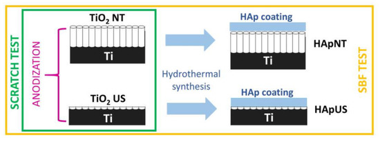
Figure 1.
Schematic overview of sample preparation, including the formation of TiO2 layers by an anodization process (u-shaped structure (US) and nanotubes (NT)) and a hydrothermal synthesis of hydroxyapatite (Hap) coating on thermally treated nanopatterned substrates (HApNT and HApUS).
2.2. Hydrothermal Synthesis of Hydroxyapatite Coatings
The synthesis of hydroxyapatite (HAp) coatings on substrates with a nanopatterned TiO2 intermediate layer (NT and US) was carried out under hydrothermal conditions according to the method described in our previous study [24]. An overview of the reactions occurring during the hydrothermal synthesis of HAp coatings is demonstrated in Figure 2. Firstly, an aqueous solution was prepared with a Ca/P ratio of 1.67 from the following ingredients: Ca(NO3)2·4H2O (0.2 M) (POCH, Gliwice, Poland), (NH4)2HPO4 (0.12 M) (POCH, Gliwice, Poland), and Na2EDTA·2H2O (0.2 M) (POCH, Gliwice, Poland). The pH of the calcium–phosphate solution was adjusted to 9.0 with a dropwise addition of ammonium hydroxide. Secondly, the nanopatterned substrates, one at a time, were fixed on a titanium holder and placed in a 200 mL glass container inside the autoclave. The holder was set at the angle of 45° to the bottom. Finally, the calcium–phosphate solution was poured into the glass vessel, allowing the samples to be completely immersed. The synthesis was carried out for 7 h at 200 °C in a sealed autoclave. After the hydrothermal process, samples were rinsed with distilled water and dried in air at room temperature.
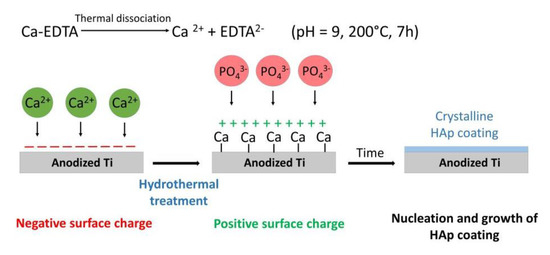
Figure 2.
Schematic presentation of chemical reactions occurring during the hydrothermal synthesis of HAp coatings on anodized and annealed Ti substrates in the form of US and NT.
2.3. Morphology, Structure, and Adhesion Characterization
The surface morphology and chemical characterization of samples was done using scanning electron microscopy (SEM, Tescan Vega 3, Fuveau, France), equipped with an energy-dispersive X-ray spectrometer (QUANTAX EDS, Bruker, Billerica, MA, USA). The chemical composition was examined using a Raman spectrometer (Almega XR of Thermo Electron Corp., Winsford, UK) equipped with an optical microscope. The Raman signal was excited at the wavelength of 532 nm. Data were collected in the spectral range from 100 to 4000 cm−1 with resolution of 2 cm−1. The XRD measurements were carried out with a PANalytical X’Pert Pro diffractometer (Almelo, Netherlands) in the standard θ–2θ geometry. The operating voltage and current were kept at 40 kV and 30 mA, respectively. The acquisition of XRD diffraction patterns was performed with a step size of 0.05° in the 2θ range from 20° to 100° using Cu Kα (λ = 1.54 Å) radiation. The angular resolution of the instrument was calibrated using an LaB6 line profile standard (SRM660a - NIST certificate [25]). We evaluated the adhesion strength of the nanopatterned samples using a combination of SEM, EDS, and a Nano-Scratch Test System (CSM Instruments, Needham, MA, USA). Scratch measurements were performed with normal load ranging from 0.1 to 100 mN and loading speed of 2 mN/s using a diamond Rockwell-tip with a top radius of 2 µm. On each type of the nanostructured titanium oxide film, we performed 10–15 scratches in different places of the samples.
2.4. Bioactivity Test in SBF
A bioactivity assessment of US and NT samples, with and without HAp coating (HApUS, HApNT), was investigated by immersion in acellular simulated body fluid (SBF) according to ISO standard 23317:2014(E) [26]. The ionic concentration of SBF was nearly equal to that of human blood plasma at 36.5 °C (Na+ 142.0, K+ 5.0, Mg2+ 1.5, Ca2+ 2.5, Cl− 147.8, HCO3− 4.2, HPO42− 1.0, and SO42− 0.5 mM), and pH was adjusted to the value of 7.40 using TRIS and HCl (1 mol dm−3). Each of the samples was incubated for two weeks at 37 °C in plastic sterile containers with 7 mL of SBF. The fluid was refreshed every three days. After two weeks, samples were removed from SBF, rinsed with distilled water, and left to dry in air. SEM study was performed on as-prepared samples before and after immersion in SBF. The time of incubation was adjusted to observe full biomineralization in vitro.
3. Results
3.1. Morphology and Structure of Nanopatterned Crystalline TiO2 Layers before and after Hydrothermal Synthesis
SEM images presenting the morphology of annealed TiO2 u-shaped nanopits and aligned nanotubes are shown in Figure 3. Both forms of anodized TiO2 nanopatterns exhibit similar inner diameters of 106 ± 8 nm for US and 104 ± 10 nm for NT, which were determined directly from SEM pictures with the assumption of a circular shape of the structures. The height of the US is approximately ½ of its diameter, while in the case of NT, the 2 h long anodization process produces a micrometer long tubular structure. Moreover, we observed distinguishable small pores within the US arrays, with diameters of approximately 30 ± 4 nm.
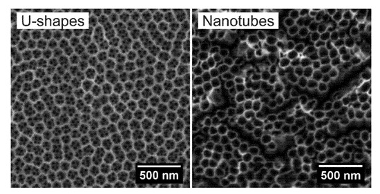
Figure 3.
SEM images of anodized and annealed TiO2 layer in the form of US and NT.
Figure 4 demonstrates an XRD and Raman study on hydrothermally treated U shapes and nanotubes (HApUS and HApNT, respectively). From the structural and chemical point of view, the fabricated US can be considered as a similar product to NT composed of two crystalline forms of titanium oxide: anatase and rutile. The XRD patterns for HApUS and HApNT samples (Figure 4) showed Bragg peaks characteristic for anatase (according to the ICSD card No. 00-004-0477), rutile (according to the ICSD card No. 00-034-0180), and α-titanium (according to the ICSD card No. 01-089-5009). The XRD patterns of hydrothermally treated US and NT confirmed also the synthesis of the HAp phase with hexagonal symmetry and space group P63/m [24,27,28]. The lattice parameters calculated for the HAp coating on US (HApUS) were a = 9.43(1) Å and c = 6.89(1) Å, whereas for the HAp coating on NT (HApNT), they were a = 9.44(1) Å and c = 6.90(1) Å. These values agree with data established for the HAp phase [29,30]. Comparing the relative intensities of reflections for the HAp structure at 2θ of 31.7°, 32.1° and 32.8°, corresponding to (211), (112), and (300) crystallographic planes, we can notice some slight differences between samples HApUS and HApNT. We associate these discrepancies with the crystallographic texture or some structural defects. Preferred crystallographic orientation might also cause an absence of XRD reflection assigned to anatase at 2θ of 37.7°, 53.7° in case of the HApUS sample. The TiO2 coating that is not produced by an electrochemical anodization process, but for instance by chemical and thermal treatment is found in rutile but not the anatase structure [24,31,32]. In our previous study concerning the synthesis of HAp coating on a nanotubular surface of TiO2 [23], we observed the tendency for crystal growth along the (001) crystallographic direction. It is noteworthy that no other forms of crystalline calcium phosphates were observed in the XRD analysis.
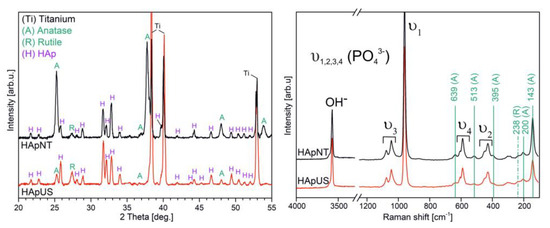
Figure 4.
XRD patterns and Raman spectra of anodized and annealed TiO2 in the form of US and NT after the hydrothermal process (HApUS and HApNT, respectively).
Analysis on the structural and chemical nature of the produced samples complementary to XRD with the use of Raman spectroscopy is shown in Figure 4. The Raman vibrational spectra of both specimens HApUS and HApNT exhibit characteristic bands for hydroxyapatite structure, including a band originating from the hydroxyl group (OH−) and four internal modes associated with the presence of the phosphate group PO43− (v1, v2, v3, v4) [27,33,34]. In both cases, we also observe five characteristic bands for anatase, which are localized at 395, 513, 143, 200, and 639 cm−1 [35]. In this study, the only characteristic Raman-active band for rutile observed in spectra of anodized and annealed titanium is at the position of 238 cm−1. The other molecule vibrations of rutile phase at 610 and 446 cm−1 overlap with the stronger intensity vibration modes assigned to the phosphate group (v2 and v4) [36].
3.2. Resistance against Scratch of Crystalline TiO2 Layers in the Form of NT and US
A combination of three methods was applied—a nano-scratch test combined with EDS and SEM measurements—to provide a comparative study on the resistance against scratch for US and NT. The conventional method for assessing adhesion of a film to the substrate requires determining the critical normal load at which the film starts to delaminate from the substrate. This estimation is based on precise measurements of friction force (with constant increase of normal load) and micrographs of the scratched surfaces from optical microscope. Due to the nano-scaled size of the nanostructures, it was difficult to determine the critical normal loads directly from optical micrographs or changes in the acoustic emission sensor output. For that reason, additional morphological and elemental analysis was required to determine the moment of coating delamination and exposition of the metallic substrate.
Figure 5 presents SEM images of sample surfaces after the scratch test performed on different areas: the beginning of the scratch (left image); the intermediate area showing a deformed but still continuous (according to EDS measurement) layer of the crystalline TiO2 (middle image), and the area of layer delamination with substrate exposition (right image). From the SEM study, we observe that there is a significant difference in the deformation mechanism under increasing load applied on the moving tip between the US and sample with NT. Just after initial indentation at the minimal load force of 0.1 mN, nanotubes began to collapse, and many large debris along the scratch’s edges can be recognized. Further analysis along the groove confirmed nanotubes’ brittleness and ability to easily break and detach from the substrate. At the initial stage of the scratch test, we observe for the US sample superior mechanical properties, i.e., a shallow penetration of the Rockwell stylus and more plastic deformation compared to the NT layer. Further SEM analysis of the intermediate part of scratches on the US reveals substrate-like inner cracks within the groove caused by plastic deformation mechanisms. The presence of perpendicular cracks implies that the material underwent compaction and abrasion by the microploughing or microcutting mechanisms under the tip movement, although the US layer maintained its continuity and good adhesion. However, after reaching a certain depth of tip penetration, some debris can be recognized close to the groove’s edges presented in the delamination area (end part of the scratch), which may indicate the predominance of brittle deformation over plastic. In the failure point, also the morphology of the scratched US surface changed during tip sliding, and there was no evidence of nanopatterned features within the groove.
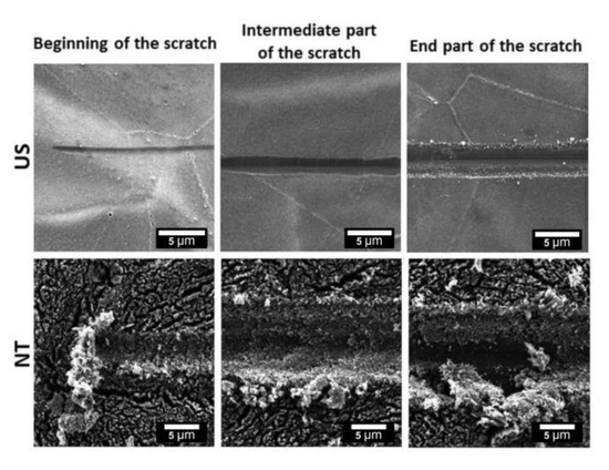
Figure 5.
SEM images showing the evolution of grooves after a scratch test on samples with crystalline TiO2 layers in the form of US and NT.
SEM images of selected areas where delamination of the TiO2 coating was identified after the scratch test, with their elemental mapping using EDS spectroscopy, are shown in Figure 6a,b for US and NT, respectively. Several profiles of EDS scans were made perpendicularly to the tip movement across all of the three grooves. Two representative profile spectra were selected to demonstrate data with titanium and oxygen signals, one showing the presence of a continuous coating within the grooves (Scan 1), and a second where delamination and exposure of the metallic substrate was found (marked with black arrows, Scan 2). The critical load was determined according to the distance at which EDS analysis showed a significant increase in signal for titanium and simultaneous decrease in signal for oxygen (Scan 2) at least for one of the grooves. In this work, the critical normal load at which we observed delamination of TiO2 film for the US sample was about twice higher than that for NT, i.e., the critical normal load was 22.0(3) mN for US and 11.0(3) mN for NT. The visible lines placed perpendicularly to the grooves on the SEM image of the US in Figure 6a are apparently caused by surface charging or superficial destruction of the TiO2 layer by electron beam during each EDS scan.
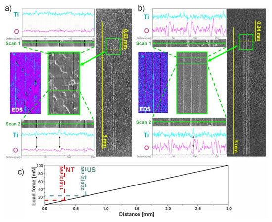
Figure 6.
SEM and energy-dispersive X-ray spectrometer (EDS) analysis after a scratch test for (a) US and (b) NT: (on the right) SEM image of scratches where the numerical scale corresponds to the length of scratches (3 mm); (in the middle) high-magnification SEM image of a selected area marked as a green square; (on the left) EDS study of the selected area; (Scan 1 and 2) line profile EDS analysis across the scratches. Image (c) demonstrates dependence of the normal force on distance and estimated values of the critical normal force at which delamination of the thorough oxide film was observed for both the US and NT.
Scratches that are demonstrated in Figure 5 and Figure 6 are representative for each kind of TiO2 film. Figure 5 shows three sections (beginning/intermediate/end), where we demonstrate sequential changes in surface morphology along one scratch and differences in deformation mechanisms that correlate with results from SEM-EDS study in Figure 6. The beginning is the starting point of each scratch, the intermediate images were taken at a similar distance from the starting point, but the end images were made at different locations from the beginning of the scratch due to a significant difference in distance between the two samples NT and US where the delamination was observed.
The reason for the better mechanical performance of the US layer is strongly related to the aspect ratio between the walls height and diameter. As we outlined earlier, the height of the US array was approximately ½ of its diameter, while NT showed a micrometer-long tubular structure. Due to the ratio between the wall height and tube diameter, NT are prone to easily brake and collapse, which have been reported by other authors on the basis of nanoindentation studies [21,37]. When the penetration of an indenter proceeds in depth, NT fracture and interact with neighboring nanotubes, causing them to bend and fracture. In the last stage of this brittle deformation, we observe a densification of NT fragments (Figure 5).
3.3. Bioactivity Analysis
One of the most important requirements for modern biomaterials used in orthopedics is the formation of chemical bonding between the material’s surface and the living bone (osseointegration). This specific implant–tissue interaction should guarantee the proper stabilization of an implant inside the body and its long-term functionality. A common method for anticipating bone-bonding ability in vitro is by soaking a sample in SBF solution. After a certain period of immersion, the formation of bone-like apatite on the material’s surface should be observed [38].
In this work, we present an EDS (Figure 7) and SEM (Figure 8) comparison study on the bioactivity of US and NT, with and without a hydrothermally synthesized HAp coating after two weeks of immersion in SBF solution. After nearly two weeks of incubation in SBF, we observed the formation of a thick layer of bone-like apatite with characteristic flower-like crystal assembly on both substrates with hydrothermally synthesized HAp coating, i.e., HApUS and HApNT (Figure 8). The main constituents that build the structure of fabricated crystalline HAp coatings are the following elements: phosphorous (P), calcium (Ca), and oxygen (O) [39]. After treatment in SBF, in addition to elements characteristic for the synthetic HAp structure, we observe in EDS spectra for HApUS and HApNT elements that are associated with a bone-like apatite structure: carbon (C), magnesium (Mg), and sodium (Na) [40]. The NT sample without HAp coating also induced the deposition of biomimetic apatite from SBF, which is in agreement with other reports on the enhancement of bioactivity in the case of crystalline TiO2 nanotubes [41,42]. In case of the US sample, which was not covered with HAp, there was no change in the surface morphology before and after soaking in SBF for 13 days (Figure 8), and its EDS spectrum after the bioactivity test did not show elements characteristic for the apatite structure (Figure 7). Some reports suggest that the certain crystallographic structure of titanium dioxide may affect the bioactivity of its surface in SBF [15,43]. Our XRD study (Figure 4) revealed that there is a difference in the relative intensity ratios of anatase to rutile between the US and NT substrates (the diffraction signal assigned to anatase and rutile is only attributed to titanium substrate), which might have had an influence on their bioactive behavior. On the other hand, it has been reported that the length of nanotubes could be a crucial factor in the ability to promote in vitro apatite formation in body fluids [41]. The study showed that 2 µm-long nanotubes were significantly more effective in forming bone-like apatite compared to 500 nm-short nanotubes. This observation could be another explanation why US with the height of their walls approximately ½ of their diameter were insufficient to promote bioactivity during the test. The possible mechanism for this could be attributed to small surface charge [31], insufficient mass transfer within the US structure, or surface roughness [44]. However, when US were coated with synthetic HAp under hydrothermal conditions, the US sample was competitive to NT high bioactivity after 2 weeks of incubation in SBF (Figure 8).
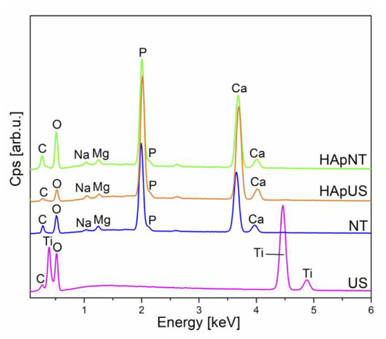
Figure 7.
EDS spectra of NT and US samples, with and without additional HAp coating, after soaking in simulated body fluid (SBF) for 2 weeks.
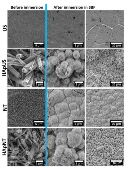
Figure 8.
SEM images (high and low magnification) of NT and US samples, with and without additional HAp coating, performed before and after soaking in SBF for 2 weeks.
4. Discussion
From the clinical point of view, at the time of implantation, orthopedic implants are subjected to considerable mechanical stress. Most of the studies focus on the biological aspect of nanotextured implants [45,46]; however, only few scientific reports consider investigating the mechanical properties of TiO2 nanotubes [21,47], especially regarding resistance to scratch [48]. According to our study, nanoscale surface topography requires a more sophisticated approach than determining the adhesion strength of an NT layer only from acoustic emission examination, friction measurements, or optical microscopy assessment. A deeper insight into evaluating the resistance against scratch of nanotextured surfaces can be achieved by combining the nano-scratch test with SEM imaging [49]. During the electrochemical growth of TiO2 NT beneath the nanotubular layer, a barrier layer of continuous oxide film is formed at the oxide/metal substrate interface [50,51]. To date, none of the adhesion studies considered the importance of this barrier layer, thus determining the critical load at which delamination of the thorough oxide layer occurs (NT layer along with barrier layer). Using SEM imaging, it is possible to evaluate with good precision the surface damage of the nanotubular structure from normal-load lateral scratches; however, it is difficult to identify when the continuous oxide barrier layer starts to delaminate. For this reason, we performed simultaneous SEM and EDS measurements to investigate when the metallic titanium substrate started to be exposed. This allowed us to determine the critical loads necessary for a complete delamination of the titanium oxide layer (NT/US layer along with barrier layer).
5. Conclusions
In this study, we present a crystalline nanoporous u-shaped structure of anodized titanium with a twice higher resistance to scratch in comparison to brittle nanotubes. We consider that this substrate could be an alternative material to nanotubes and suitable as a smart drug delivery platform. Furthermore, the US titanium substrate was successfully functionalized with hydroxyapatite coating (HApUS) under hydrothermal conditions and showed high bioactivity after 2 weeks of immersion in SBF. We reported in our previous studies [30,33] the positive effect of hydrothermally synthesized HAp coatings on titanium substrates on osteoblast-like and preosteoblast cell proliferation and adhesion. Taking into consideration the combination of superior mechanical performance of the US substrate and high bioactivity of HAp coating, we are convinced, that this surface modification may improve the performance of currently used titanium-based implants for orthopedic applications.
Author Contributions
Methodology, A.B.; validation, A.Z.; formal analysis, A.B.; investigation, A.B.; data curation, A.B.; writing—original draft preparation, A.B.; writing—review and editing, A.Z. and M.M.; visualization, A.B.; supervision, M.M.; methodology, S.K. and M.P. All authors have read and agreed to the published version of the manuscript.
Funding
Financial support of the SEM Tescan Vega 3 instrument from the Polish National Science Centre (NCN), grant UMO-2014/13/B/ST5/04497. This study was also partially supported by NCN regarding patterning and anodization procedure of titanium substrate from grant UMO-2015/19/D/ST3/01843.
Conflicts of Interest
The authors declare no conflict of interest.
References
- Kokubo, T. Design of bioactive bone substitutes based on biomineralization process. Mater. Sci. Eng. C 2005, 25, 97–104. [Google Scholar] [CrossRef]
- Von Wilmowsky, C.; Bauer, S.; Lutz, R.; Meisel, M.; Neukam, F.W.; Toyoshima, T.; Schmuki, P.; Nkenke, E.; Schlegel, K.A. In Vivo Evaluation of Anodic TiO2 Nanotubes; An Experimental Study in the Pig. J. Biomed. Mater. Res. Part B Appl. Biomater. 2009, 89, 165–171. [Google Scholar] [CrossRef]
- Ratner, D.B.; Brunette, D.M.; Tengvall, P.; Textor, M.; Thomsen, P. Titanium in Medicine, 1st ed.; Springer: Berlin/Heidelberg, Germany, 2008; ISBN 0954411021. [Google Scholar]
- Chen, Q.; Thouas, G.A. Metallic implant biomaterials. Mater. Sci. Eng. R Rep. 2015, 87, 1–57. [Google Scholar] [CrossRef]
- Choroszyński, M.; Choroszyński, M.R.; Skrzypek, S.J. Biomaterials for hip implants—Important considerations relating to the choice of materials. Bio-Algorithms Med-Syst. 2017, 13, 133–145. [Google Scholar] [CrossRef]
- Wennerberg, A. The importance of surface roughness for implant incorporation. Int. J. Mach. Tools Manuf. 1998, 38, 657–662. [Google Scholar] [CrossRef]
- Suzuki, K.; Aoki, K.; Ohya, K. Effects of surface roughness of titanium implants on bone remodeling activity of femur in rabbits. Bone 1997, 21, 507–514. [Google Scholar] [CrossRef]
- Suska, F.; Emanuelsson, L.; Johansson, A.; Tengvall, P.; Thomsen, P. Fibrous capsule formation around titanium and copper. J. Biomed. Mater. Res. Part A 2008, 85, 888–896. [Google Scholar] [CrossRef]
- Lemons, J.E. Biomaterials, Biomechanics, Tissue Healing, and Immediate-Function Dental Implants. J. Oral Implantol. 2004, 30, 318–324. [Google Scholar] [CrossRef]
- Li, Y.; Song, Y.; Ma, A.; Li, C. Surface immobilization of TiO2 nanotubes with bone morphogenetic protein-2 synergistically enhances initial preosteoblast adhesion and osseointegration. BioMed Res. Int. 2019. [Google Scholar] [CrossRef]
- Oliveira, W.F.; Arruda, I.R.S.; Silva, G.M.M.; Machado, G.; Coelho, L.C.B.B.; Correia, M.T.S. Functionalization of titanium dioxide nanotubes with biomolecules for biomedical applications. Mater. Sci. Eng. C 2017, 81, 597–606. [Google Scholar] [CrossRef]
- De Melo, C.M.L.; De Castro, M.C.A.B.; De Oliveira, A.P.; Gomes, F.O.S.; Pereira, V.R.A.; Correia, M.T.S.; Coelho, L.C.B.B.; Paiva, P.M.G. Immunomodulatory response of Cramoll 1,4 lectin on experimental lymphocytes. Phytother. Res. 2010, 24, 1631–1636. [Google Scholar] [CrossRef] [PubMed]
- Jayanthi, S.; Ishwarya, R.; Anjugam, M.; Iswarya, A.; Karthikeyan, S.; Vaseeharan, B. Purification, characterization and functional analysis of the immune molecule lectin from the haemolymph of blue swimmer crab Portunus pelagicus and their antibiofilm properties. Fish Shellfish Immunol. 2017, 62, 227–237. [Google Scholar] [CrossRef] [PubMed]
- Wang, Y.; Wen, C.; Hodgson, P.; Li, Y. Biocompatibility of TiO2 nanotubes with different topographies. J. Biomed. Mater. Res. Part A 2014, 102, 743–751. [Google Scholar] [CrossRef]
- Hilario, F.; Roche, V.; Nogueira, R.P.; Junior, A.M.J. Influence of morphology and crystalline structure of TiO2 nanotubes on their electrochemical properties and apatite-forming ability. Electrochim. Acta 2017, 245, 337–349. [Google Scholar] [CrossRef]
- Zhao, L.; Mei, S.; Chu, P.K.; Zhang, Y.; Wu, Z. The influence of hierarchical hybrid micro/nano-textured titanium surface with titania nanotubes on osteoblast functions. Biomaterials 2010, 31, 5072–5082. [Google Scholar] [CrossRef]
- Wang, N.; Li, H.; Lü, W.; Li, J.; Wang, J.; Zhang, Z.; Liu, Y. Effects of TiO2 nanotubes with different diameters on gene expression and osseointegration of implants in minipigs. Biomaterials 2011, 32, 6900–6911. [Google Scholar] [CrossRef]
- Wang, Q.; Huang, J.Y.; Li, H.Q.; Chen, Z.; Zhao, A.Z.J.; Wang, Y.; Zhang, K.Q.; Sun, H.T.; Al-Deyab, S.S.; Lai, Y.K. TiO2 nanotube platforms for smart drug delivery: A review. Int. J. Nanomed. 2016, 11, 4819–4834. [Google Scholar] [CrossRef]
- Wang, Q.; Huang, J.Y.; Li, H.Q.; Zhao, A.Z.J.; Wang, Y.; Zhang, K.Q.; Sun, H.T.; Lai, Y.K. Recent advances on smart TiO2 nanotube platforms for sustainable drug delivery applications. Int. J. Nanomed. 2017, 12, 151–165. [Google Scholar] [CrossRef]
- Feng, W.; Geng, Z.; Li, Z.; Cui, Z.; Zhu, S.; Liang, Y.; Liu, Y.; Wang, R.; Yang, X. Controlled release behaviour and antibacterial effects of antibiotic-loaded titania nanotubes. Mater. Sci. Eng. C 2016, 62, 105–112. [Google Scholar] [CrossRef]
- Xu, Y.N.; Liu, M.N.; Wang, M.C.; Oloyede, A.; Bell, J.M.; Yan, C. Nanoindentation study of the mechanical behavior of TiO2 nanotube arrays. J. Appl. Phys. 2015, 118, 145301. [Google Scholar] [CrossRef]
- Li, Y.; Li, B.; Song, Y.; Ma, A.; Li, C.; Zhang, X.; Li, H.; Zhang, Q.; Zhang, K. Improved osteoblast adhesion and osseointegration on TiO2 nanotubes surface with hydroxyapatite coating. Dent. Mater. J. 2019, 38, 278–286. [Google Scholar] [CrossRef] [PubMed]
- Suchanek, K.; Hajdyła, M.; Maximenko, A.; Zarzycki, A.; Marszałek, M.; Jany, B.R.; Krok, F. The influence of nanoporous anodic titanium oxide substrates on the growth of the crystalline hydroxyapatite coatings. Mater. Chem. Phys. 2017, 186, 167–178. [Google Scholar] [CrossRef]
- Suchanek, K.; Bartkowiak, A.; Gdowik, A.; Perzanowski, M.; Kąc, S.; Szaraniec, B.; Suchanek, M.; Marszałek, M. Crystalline hydroxyapatite coatings synthesized under hydrothermal conditions on modified titanium substrates. Mater. Sci. Eng. C 2015, 51, 57–63. [Google Scholar] [CrossRef]
- Standard Reference Material 660a; National Institute of Standards & Technology: Gaithersburg, MD, USA, 2000.
- International Standard ISO 23317. Implants for Surgery—In Vitro Evaluation for Apatite-Forming Ability of Implant Materials, 3rd ed.; 06-15-2014; ISO: Geneva, Switzerland, 2014. [Google Scholar]
- Neira, I.S.; Guitian, F.; Taniguchi, T.; Watanabe, T.; Yoshimura, M. Hydrothermal synthesis of hydroxyapatite whiskers with sharp faceted hexagonal morphology. J. Mater. Sci. 2008, 43, 2171–2178. [Google Scholar] [CrossRef]
- Yang, Y.; Wu, Q.; Wang, M.; Long, J.; Mao, Z.; Chen, X. Hydrothermal synthesis of hydroxyapatite with different morphologies: Influence of supersaturation of the reaction system. Cryst. Growth Des. 2014, 14, 4864–4871. [Google Scholar] [CrossRef]
- Koutsopoulos, S. Synthesis and characterization of hydroxyapatite crystals: A review study on the analytical methods. J. Biomed. Mater. Res. 2002, 62, 600–612. [Google Scholar] [CrossRef]
- Suchanek, K.; Perzanowski, M.; Suchy, K.; Lekka, M.; Szaraniec, B.; Marszałek, M. Assessment of phase stability and in vitro biological properties of hydroxyapatite coatings composed of hexagonal rods. Surf. Coat. Technol. 2019, 364, 298–305. [Google Scholar] [CrossRef]
- Kokubo, T.; Pattanayak, D.K.; Yamaguchi, S.; Takadama, H.; Matsushita, T.; Kawai, T.; Takemoto, M.; Fujibayashi, S.; Nakamura, T. Positively charged bioactive Ti metal prepared by simple chemical and heat treatments. J. R. Soc. Interface 2010, 7 (Suppl. 5), S503–S513. [Google Scholar] [CrossRef]
- Pattanayak, D.K.; Yamaguchi, S.; Matsushita, T.; Nakamura, T.; Kokubo, T. Apatite-forming ability of titanium in terms of pH of the exposed solution. J. R. Soc. Interface 2012, 9, 2145–2155. [Google Scholar] [CrossRef]
- Bartkowiak, A.; Suchanek, K.; Menaszek, E.; Szaraniec, B.; Lekki, J.; Perzanowski, M.; Marszałek, M. Biological effect of hydrothermally synthesized silica nanoparticles within crystalline hydroxyapatite coatings for titanium implants. Mater. Sci. Eng. C 2018, 92, 88–95. [Google Scholar] [CrossRef]
- Suchanek, K.; Bartkowiak, A.; Perzanowski, M.; Marszałek, M. From monetite plate to hydroxyapatite nanofibers by monoethanolamine assisted hydrothermal approach. Sci. Rep. 2018, 8, 15408. [Google Scholar] [CrossRef] [PubMed]
- Swamy, V.; Kuznetsov, A.; Dubrovinsky, L.S.; Caruso, R.A.; Shchukin, D.G.; Muddle, B.C. Finite-size and pressure effects on the Raman spectrum of nanocrystalline anatase TiO2. Phys. Rev. B 2005, 71, 184302. [Google Scholar] [CrossRef]
- Hardcastle, F.D.; Ishihara, H.; Sharma, R.; Biris, A.S. Photoelectroactivity and Raman spectroscopy of anodized titania (TiO2) photoactive water-splitting catalysts as a function of oxygen-annealing temperature. J. Mater. Chem. 2011, 21, 6337. [Google Scholar] [CrossRef]
- Shokuhfar, T.; Arumugam, G.K.; Heiden, P.A.; Yassar, R.S.; Friedrich, C. Direct compressive measurements of individual titanium dioxide nanotubes. ACS Nano 2009, 3, 3098–3102. [Google Scholar] [CrossRef] [PubMed]
- Kokubo, T.; Takadama, H. How useful is SBF in predicting in vivo bone bioactivity? Biomaterials 2006, 27, 2907–2915. [Google Scholar] [CrossRef]
- Suchanek, K.; Bartkowiak, A.; Perzanowski, M.; Marszałek, M.; Sowa, M.; Simka, W. Electrochemical properties and bioactivity of hydroxyapatite coatings prepared by MEA/EDTA double-regulated hydrothermal synthesis. Electrochim. Acta 2019, 298, 685–693. [Google Scholar] [CrossRef]
- Kokubo, T.; Kim, H.M.; Kawashita, M. Novel bioactive materials with different mechanical properties. Biomaterials 2003, 24, 2161–2175. [Google Scholar] [CrossRef]
- Tsuchiya, H.; Macak, J.M.; Müller, L.; Kunze, J.; Müller, F.; Greil, P.; Virtanen, S.; Schmuki, P. Hydroxyapatite growth on anodic TiO2 nanotubes. J. Biomed. Mater. Res. Part A 2006, 77, 534–541. [Google Scholar] [CrossRef]
- Kunze, J.; Müller, L.; Macak, J.M.; Greil, P.; Schmuki, P.; Müller, F.A. Time-dependent growth of biomimetic apatite on anodic TiO2 nanotubes. Electrochim. Acta 2008, 53, 6995–7003. [Google Scholar] [CrossRef]
- Uchida, M.; Kim, H.M.; Kokubo, T.; Fujibayashi, S.; Nakamura, T. Structural dependence of apatite formation on titania gels in a simulated body fluid. J. Biomed. Mater. Res. Part A 2003, 64, 164–170. [Google Scholar] [CrossRef]
- Hao, Y.Q.; Li, S.J.; Hao, Y.L.; Zhao, Y.K.; Ai, H.J. Effect of nanotube diameters on bioactivity of a multifunctional titanium alloy. Appl. Surf. Sci. 2013, 268, 44–51. [Google Scholar] [CrossRef]
- Park, H.H.; Park, I.S.; Kim, K.S.; Jeon, W.Y.; Park, B.K.; Kim, H.S.; Bae, T.S.; Lee, M.H. Bioactive and electrochemical characterization of TiO2 nanotubes on titanium via anodic oxidation. Electrochim. Acta 2010, 55, 6109–6114. [Google Scholar] [CrossRef]
- Lee, J.K.; Choi, D.S.; Jang, I.; Choi, W.Y. Improved osseointegration of dental titanium implants by TiO2 nanotube arrays with recombinant human bone morphogenetic protein-2: A pilot in vivo study. Int. J. Nanomed. 2015, 10, 1145–1154. [Google Scholar] [CrossRef]
- Chang, W.Y.; Fang, T.H.; Chiu, Z.W.; Hsiao, Y.J.; Ji, L.W. Nanomechanical properties of array TiO2 nanotubes. Microporous Mesoporous Mater. 2011, 145, 87–92. [Google Scholar] [CrossRef]
- Sarraf, M.; Razak, B.A.; Crum, R.; Gámez, C.; Ramirez, B.; Abu Kasim, N.H.B.; Nasiri-Tabrizi, B.; Gupta, V.; Sukiman, N.L.; Basirun, W.J. Adhesion measurement of highly-ordered TiO2 nanotubes on Ti-6Al-4V alloy. Process. Appl. Ceram. 2017, 11, 311–321. [Google Scholar] [CrossRef]
- Descamps, S.; Awitor, K.O.; Raspal, V.; Johnson, M.B.; Bokalawela, R.S.P.; Larson, P.R.; Doiron, C.F. Mechanical Properties of Nanotextured Titanium Orthopedic Screws for Clinical Applications. J. Med. Devices 2013, 7, 210051–210055. [Google Scholar] [CrossRef]
- Acevedo-Peña, P.; Lartundo-Rojas, L.; González, I. Effect of water and fluoride content on morphology and barrier layer properties of TiO2 nanotubes grown in ethylene glycol-based electrolytes. J. Solid State Electrochem. 2013, 17, 2939–2947. [Google Scholar] [CrossRef]
- Anitha, V.C.; Banerjee, A.N.; Joo, S.W.; Min, B.K. Barrier-oxide layer engineering of TiO2 nanotube arrays to get single-and multi-stage Y-branched nanotubes: Effect of voltage ramping and electrolyte conductivity. Mater. Sci. Eng. B 2015, 195, 1–11. [Google Scholar] [CrossRef]


Publisher’s Note: MDPI stays neutral with regard to jurisdictional claims in published maps and institutional affiliations. |
© 2020 by the authors. Licensee MDPI, Basel, Switzerland. This article is an open access article distributed under the terms and conditions of the Creative Commons Attribution (CC BY) license (http://creativecommons.org/licenses/by/4.0/).