Application of Plasma Sprayed Cu Intermediate Layers in the Soldering Process of Graphite Composite to 6060 Aluminum Alloy


Abstract
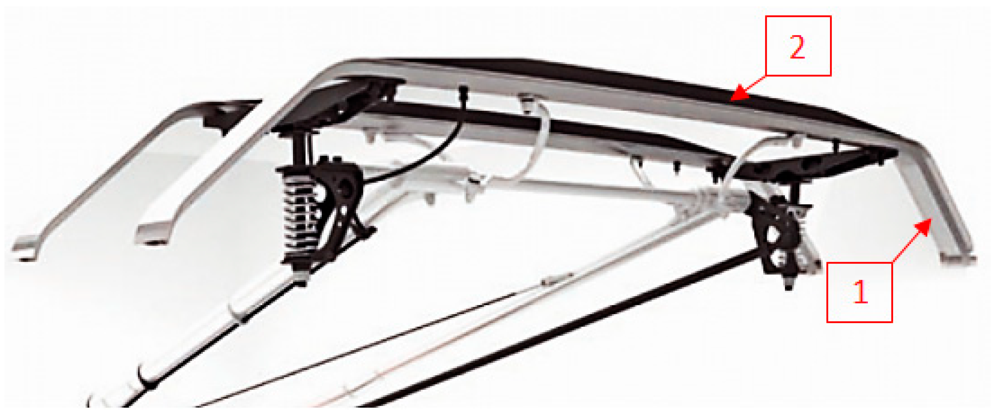
1. Introduction
2. Materials and Methods
2.1. Materials
- shore hardness of about 90 oSh D (about 100 HV);
- good tribological performance (wear rate about 2 × 10⁻⁷ mm3/Nm)-graphite acts as a lubricant;
- high electrical conductivity;
- total porosity up to 10%;
- negligible liquid absorption.
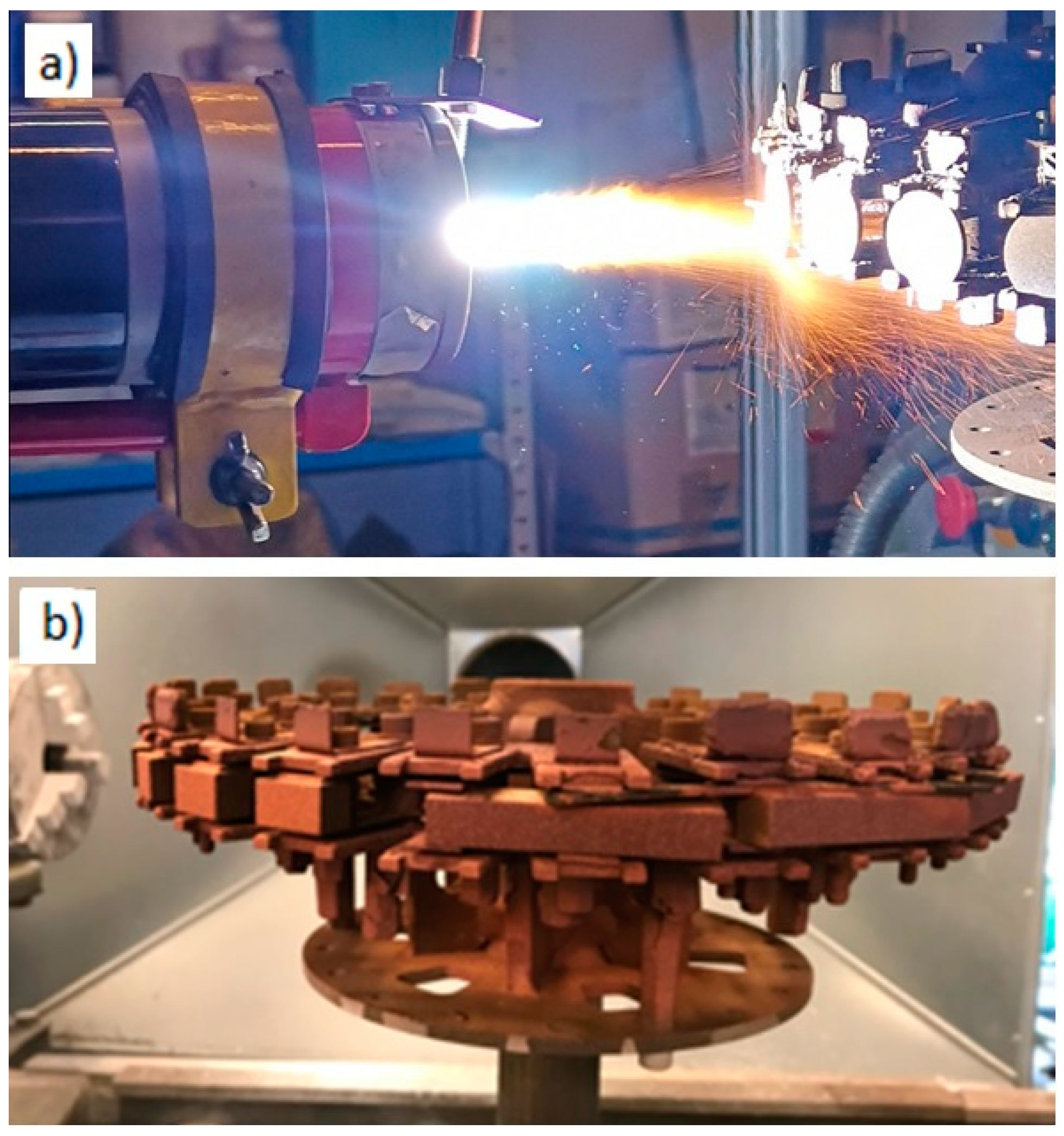
2.2. Joint Formulation
3. Results and Discussion
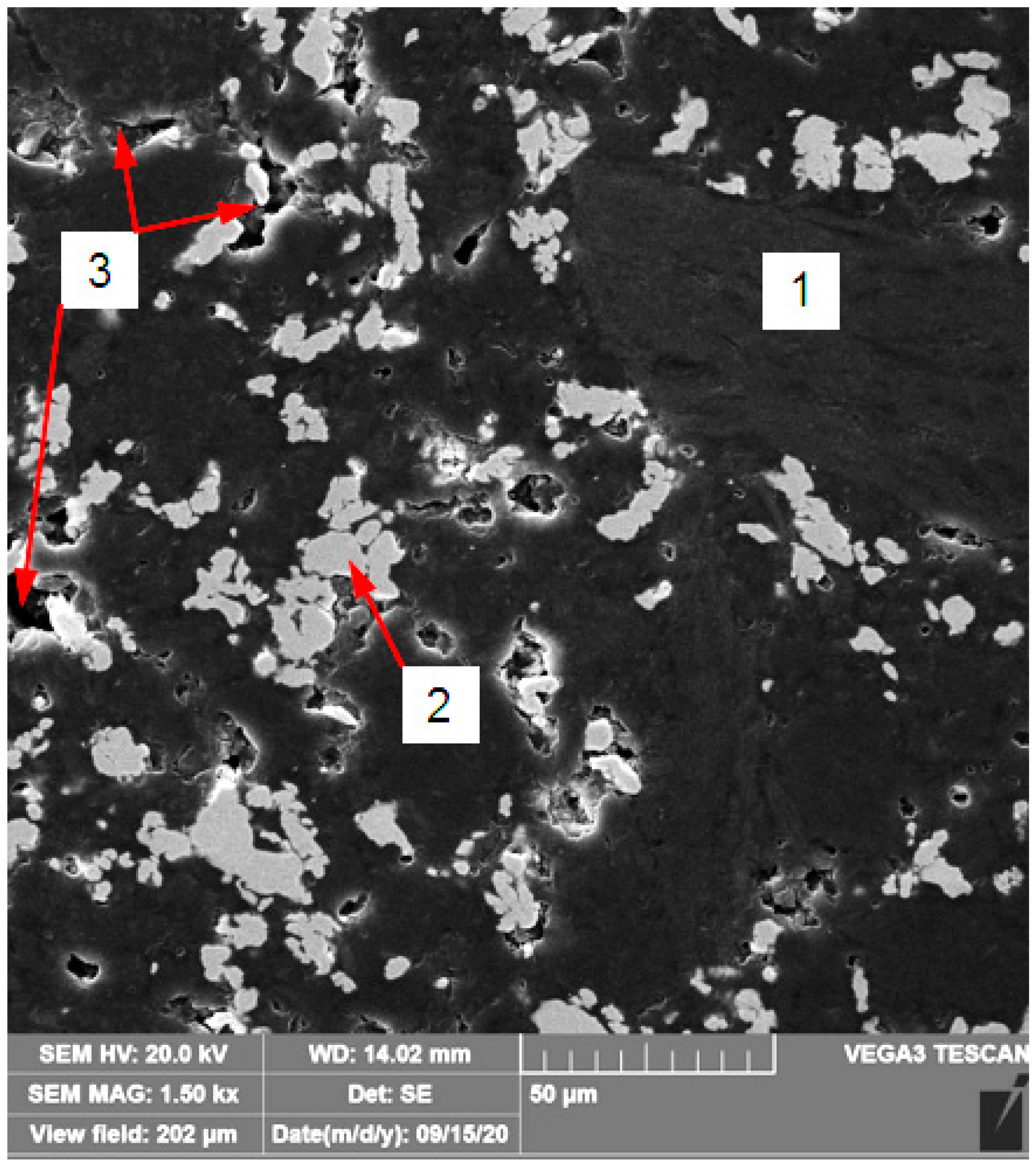
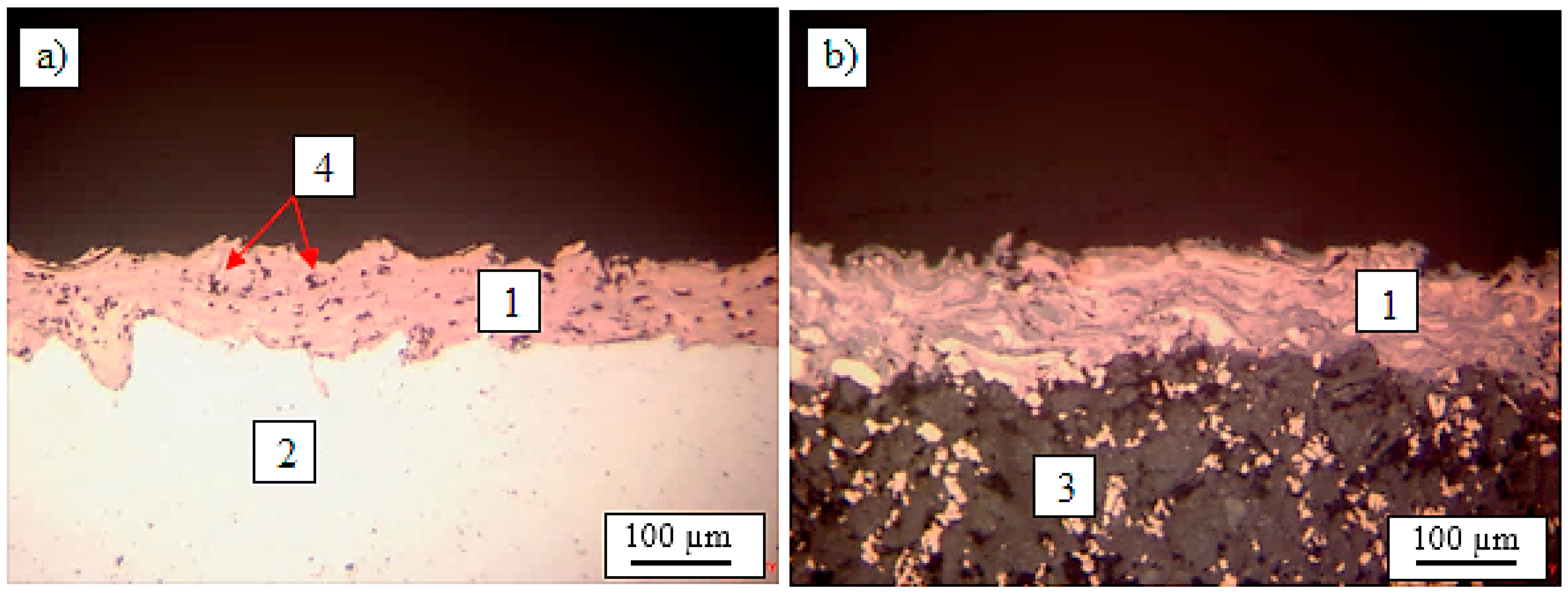
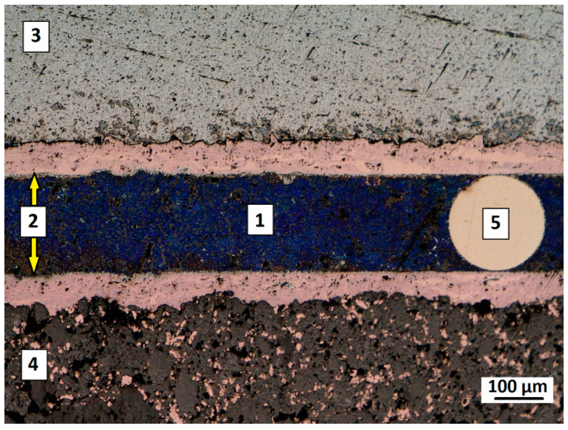
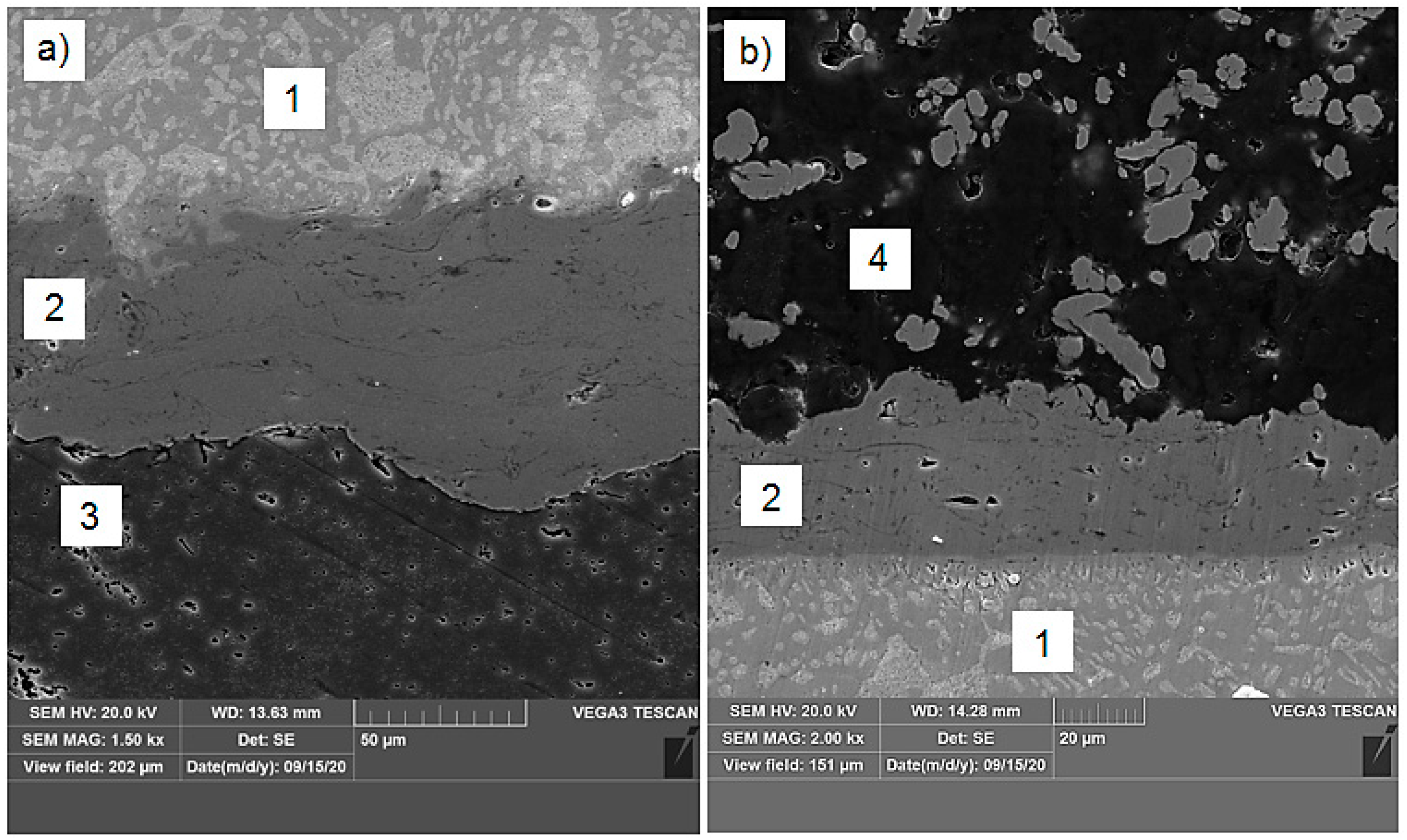
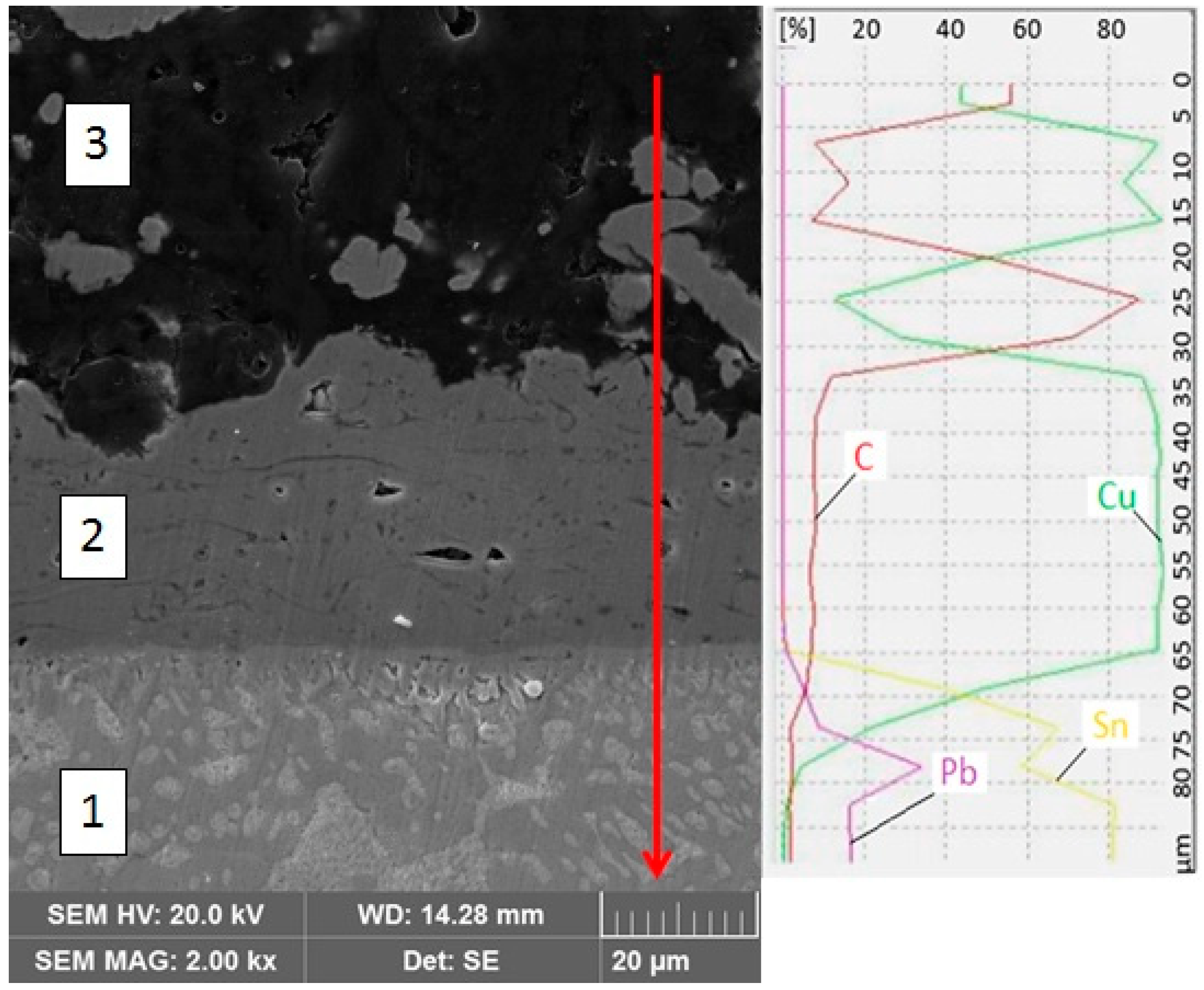
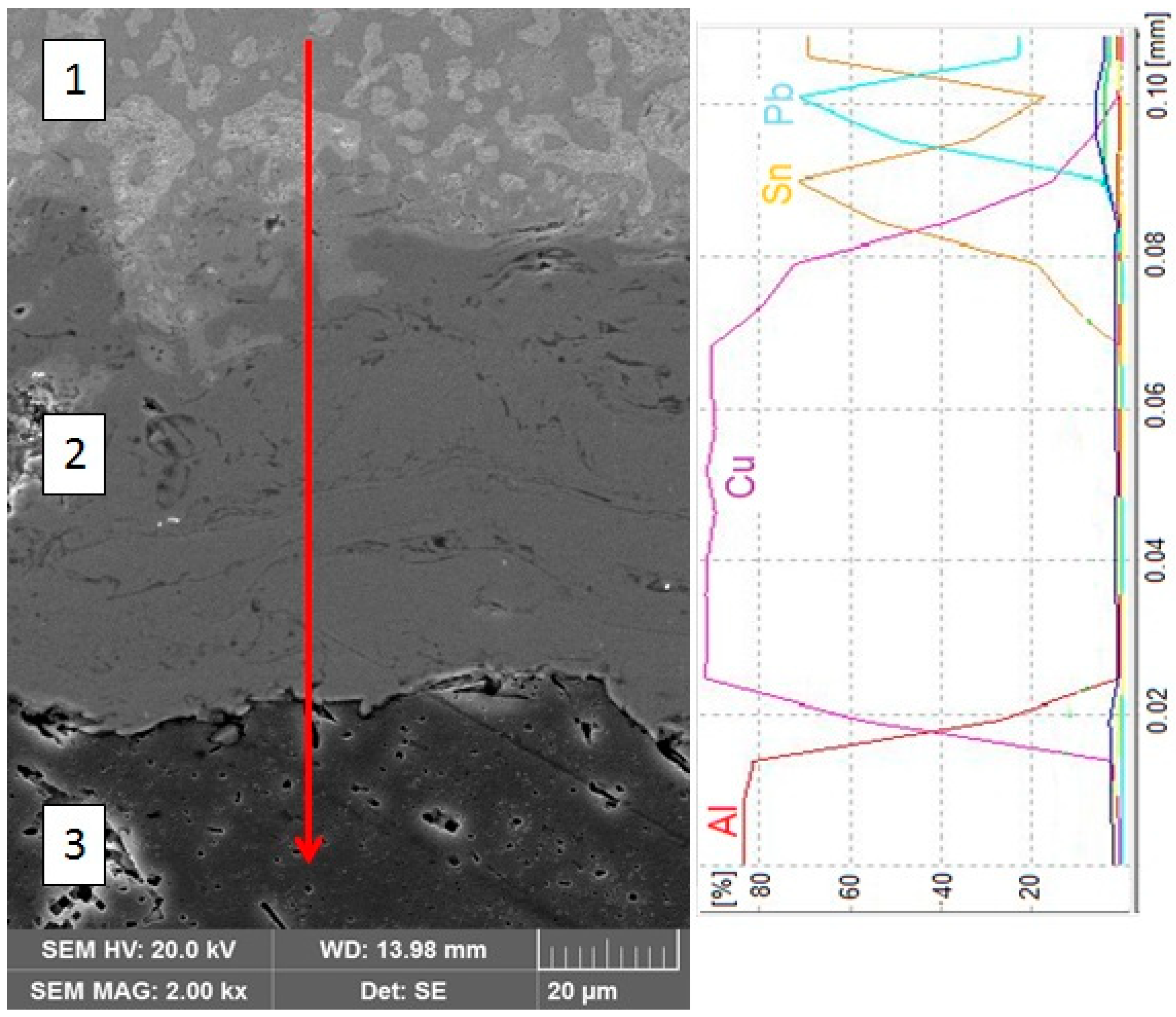
3.1. Metallography
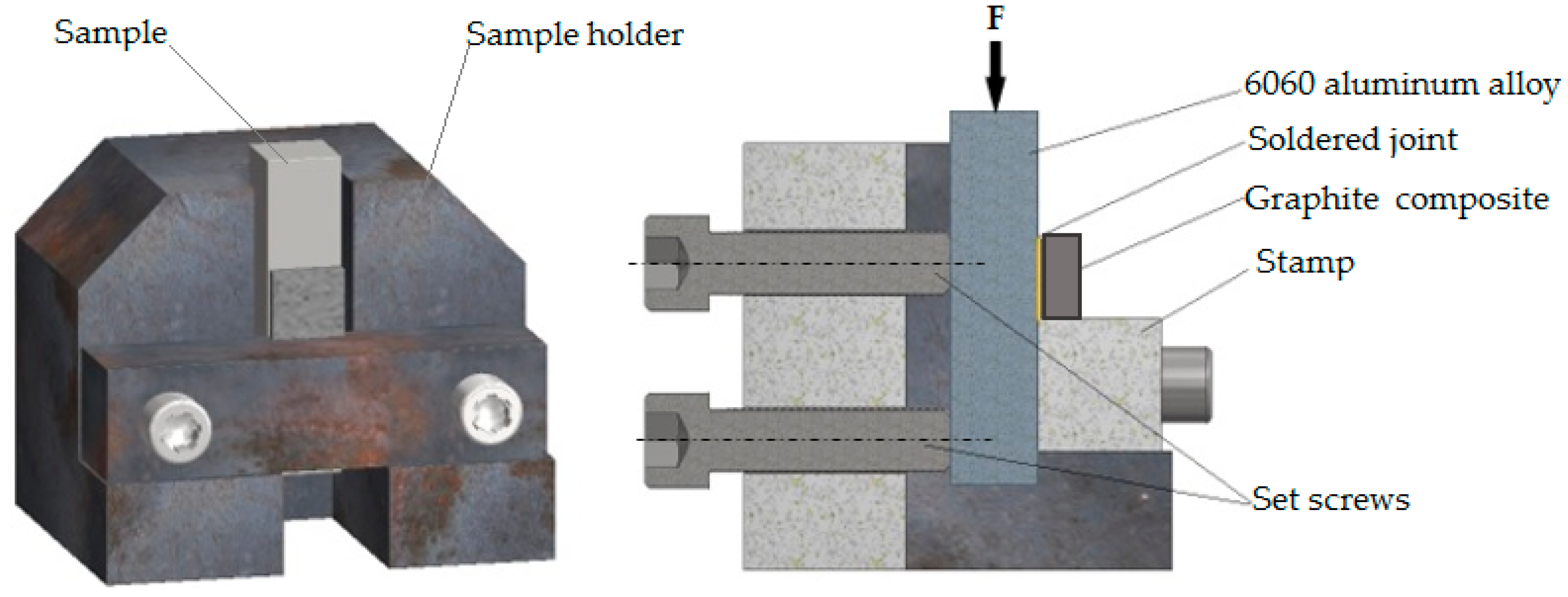
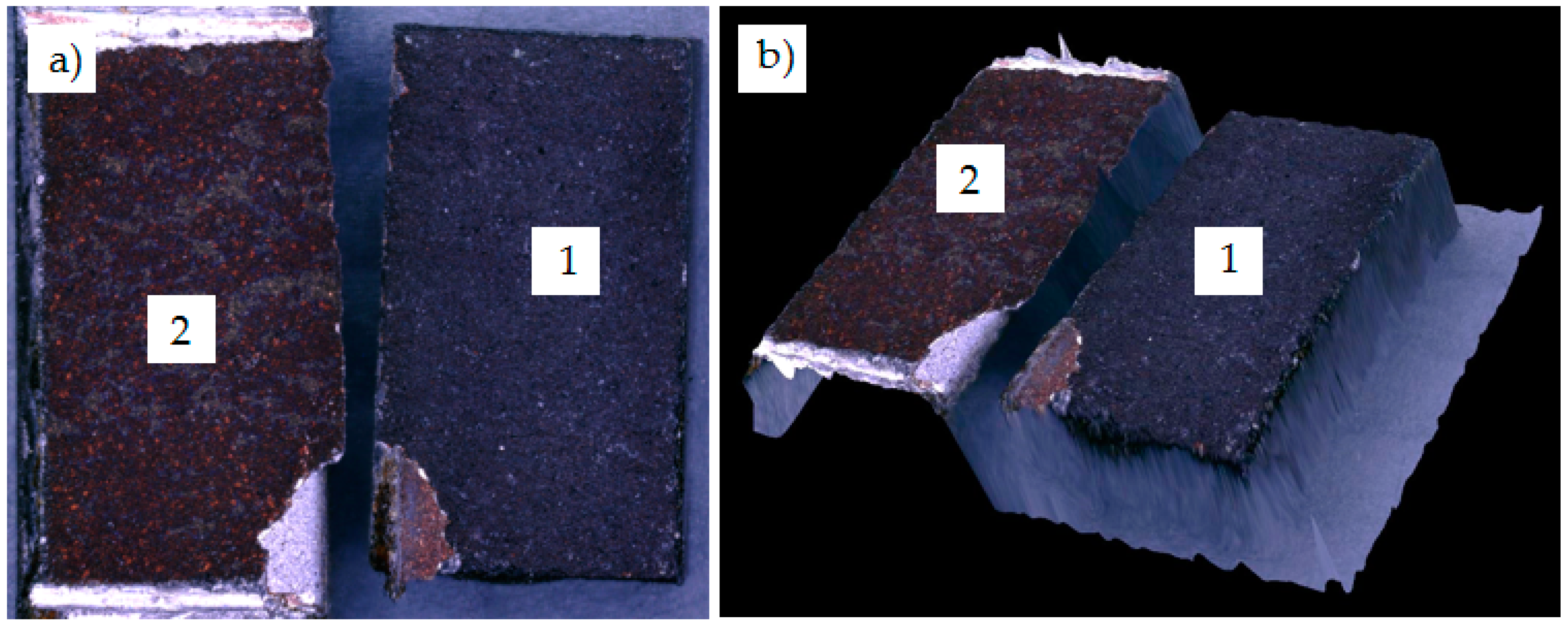
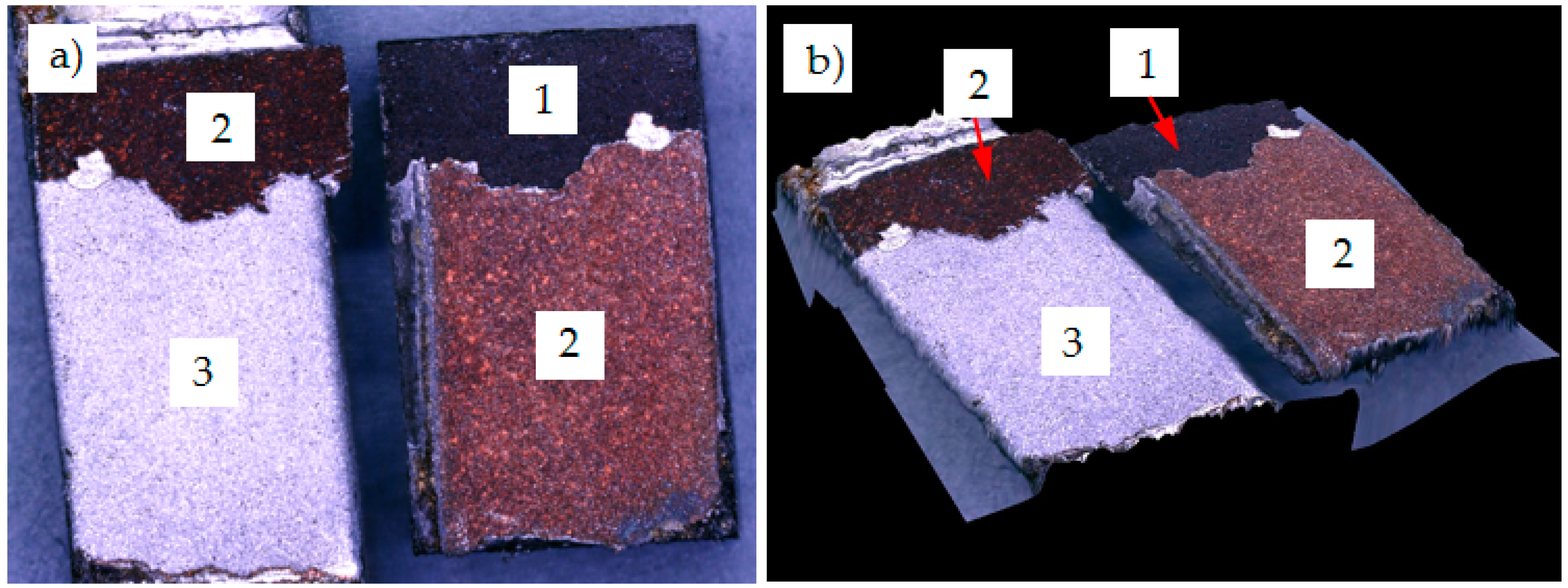
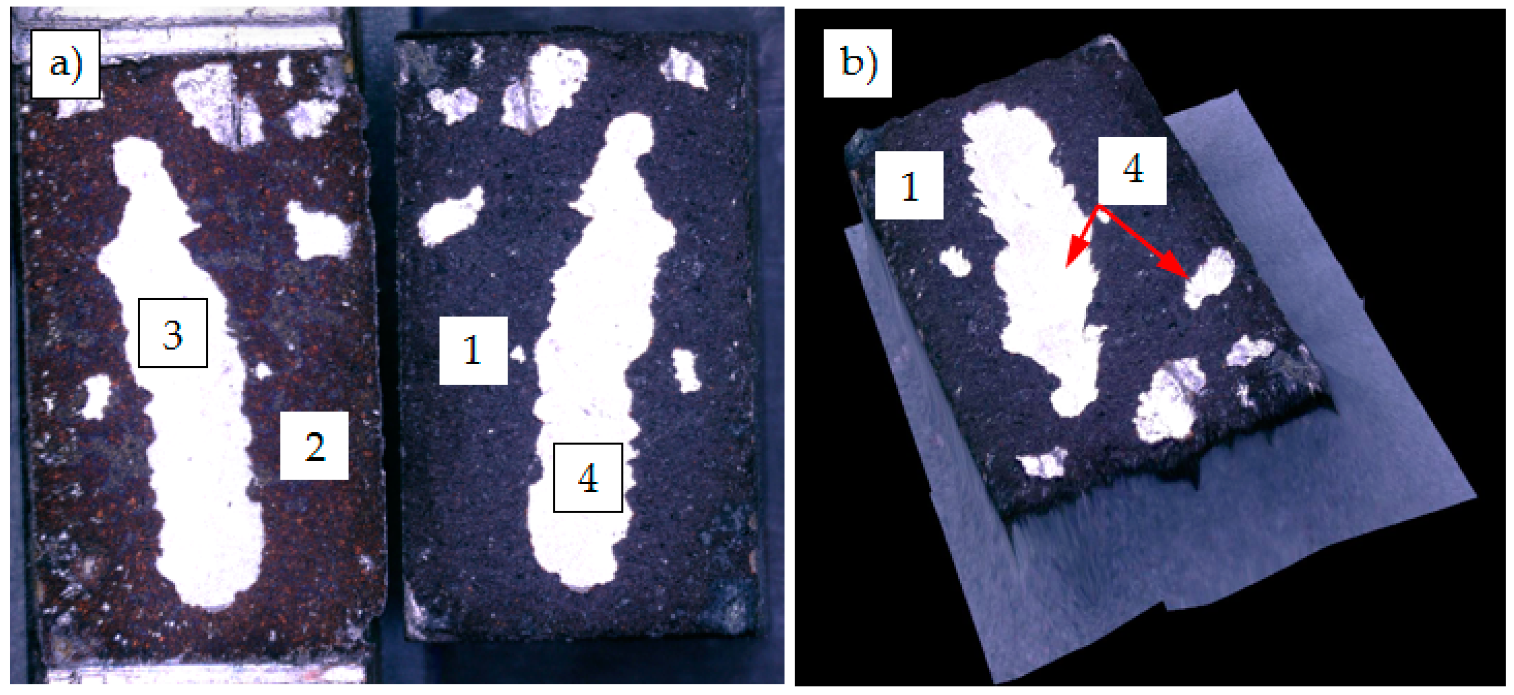
3.2. Mechanical Properties of Soldered Joints
- test speed of 2 mm/min;
- load up to 10 kN.
4. Conclusions
Author Contributions
Funding
Conflicts of Interest
References
- Wojdat, T.; Winnicki, M.; Łamasz, S.; Żuk, A. Application of interlayers in the soldering process of graphite composite to aluminium alloy 6060. Arch. Civ. Mech. Eng. 2019, 1, 91–99. [Google Scholar] [CrossRef]
- Mirski, Z.; Ciepacz, I.; Zimniak, Z.; Granat, K.; Wojdat, T. Galvanized coatings in connecting difficult-to-bond materials. Pt. 1, Influence of surface preparation on the adhesion of galvanized coatings to a non-metal substrate. Corros. Prot. 2017, 5, 166–169. [Google Scholar] [CrossRef]
- Yang, H.; Luo, R.; Han, S.; Li, M. Effect of the ratio of graphite/pitch coke on the mechanical and tribological properties of copper–carbon composites. Wear 2010, 268, 1337–1341. [Google Scholar] [CrossRef]
- Rahn, A. The Basics of Soldering; Wiley-Interscience: New York, NY, USA, 1993. [Google Scholar]
- Champagne, V.K. The Cold Spray Materials Deposition Process—Fundamentals and Applications; Woodhead Publishing Limited: Cambridge, UK, 2007. [Google Scholar]
- Wielage, B.; Wank, A.; Grund, T.H. Thermally Sprayed Solder/Braze Filler Alloys for the Joining of Light Metals; The XII Workshop Plasmatechnik: Ilmenau, Germany, 2004. [Google Scholar]
- Mirski, Z.; Granat, K.; Prasałek, A. The diffusive barriers in copper brazing with austenitic steel by use the Cu-Ag-P (L-Ag15P) filler metal. Arch. Metall. Mater. 2008, 4, 1035–1046. [Google Scholar]
- Wojdat, T.; Winnicki, M.; Rutkowska-Gorczyca, M.; Krupiński, S.; Kubica, K. Soldering aluminium to copper with the use of interlayers deposited by cold spraying. Arch. Civ. Mech. Eng. 2016, 16, 835–844. [Google Scholar] [CrossRef]
- Zimniak, Z.; Mirski, Z.; Ciepacz, I.; Granat, K.; Wojdat, T. The influence of cold plasma-surface modification on the grip of the electroplating finish to graphite composite and for its usefulness in soldering processes. Weld. Tech. Rev. 2018, 2, 18–21. [Google Scholar] [CrossRef][Green Version]
- Mirski, Z.; Wojdat, T.; Piwowarczyk, T.; Granat, K.; Derlukiewicz, W.; Ciepacz, I.; Jakubczuk, A. Soldering of graphite composite with PA38 aluminum alloy. Weld. Tech. Rev. 2016, 9, 50–55. [Google Scholar]
- Gärtner, F.; Stoltenhoff, T.; Voyer, J.; Kreye, H.; Riekehr, S.; Kocak, M. Mechanical properties of cold-sprayed and thermally sprayed copper coatings. Surf. Coat. Technol. 2006, 200, 770–782. [Google Scholar] [CrossRef]
- Assadi, H.; Gärtner, F.; Stoltenhoff, T.; Kreye, H. Bonding mechanism in cold gas spraying. Acta Materialia. 2003, 51, 4379–4394. [Google Scholar] [CrossRef]
- Maev, R.G.; Leshchynsky, V. Introduction to Low Pressure Gas Dynamic Spray; WILEY-VCH Verlag GmbH & Co. KGaA: Weinheim, Germany, 2008. [Google Scholar]
- Koivuluoto, H.; Vuoristo, P. Effect of Powder Type and Composition on Structure and Mechanical Properties of Cu+Al2O3 Coatings Prepared by using Low-Pressure Cold Spray Process. J. Therm. Spray Technol. 2010, 19, 1081–1092. [Google Scholar] [CrossRef]
- Koivuluoto, H.; Lagerbom, J.; Kylmalahti, M.; Vuoristo, P. Microstructure and Mechanical Properties of Low-Pressure Cold-Sprayed (LPCS) Coatings. J. Therm. Spray Technol. 2008, 17, 721–727. [Google Scholar] [CrossRef]
- Spencer, K.; Fabijanic, D.M.; Zhang, M.X. The use of Al–Al2O3 cold spray coatings to improve the surface properties of magnesium alloys. Surf. Coat. Technol. 2009, 204, 336–344. [Google Scholar] [CrossRef]
- Thermal Spraying Coatings. Available online: http://www.pnc.plPNC (accessed on 14 May 2020).
- Pilarczyk, J. Engineer’s Guide; Welding, WNT: Warsaw, Poland, 2005; Volume 2. [Google Scholar]
- Ruzbarsky, J.; Panda, A. Plasma and Thermal Spraying. Springerbriefs in Applied Sciences and Technology; Springer International Publishing: New York, NY, USA, 2017. [Google Scholar]
- Wojdat, T. Effect of surface treatment using cold plasma for adhesion of galvanic coating to graphite composite and its suitability in soldering processes, X Jubilee Conference. In Proceedings of the Physical and Mathematical Modeling of Manufacturing Processes, Jabłonna, Poland, 21–23 May 2017. [Google Scholar]
- EN 573-3:2014-02 Aluminum and Aluminum Alloys—Chemical Composition and Form of Wrought Products—Part 3: Chemical Composition and Form of Products; European Committee for Standardization: Brussels, Belgium, 2014.
- Kaniewski, M. Current collectors used in the European railway network. TTS Tech. Transp. Szyn. 2004, 1–2, 61–65. [Google Scholar]
- EN ISO 9453: 2014-11 Soft Solder Alloys—Chemical Compositions and Forms; European Committee for Standardization: Brussels, Belgium, 2014.
- ASTM C633-13 Standard Test Method for Adhesion or Cohesion Strength of Thermal Spray Coatings; ASTM International: West Conshohocken, PA, USA, 2014.
- ATSM E2546 Standard Standard Practice for Instrumented Indentation Testing; ASTM International: West Conshohocken, PA, USA, 2015.
- Kamal, S.E. Mat, Mariyam Jameelah Ghazali, and Shahrum Abdullah. Effect of Plasma Spray Variables on Cu-Ni Coated A7075. Key Eng. Mater. 2011, 462–463, 692–697. [Google Scholar] [CrossRef]
- Iordanova, I.; Forcey, K.S.; Gergov, B.; Bojinov, V. Characterization of flame-sprayed and plasma-sprayed pure metallic and alloyed coatings. Surf. Coat. Technol. 1995, 72, 23–29. [Google Scholar] [CrossRef]
- Masoumeh, G.; Shahrooz, S.; Mahmood, G.; Salar, E.A. Investigation of stand-off distance effect on structure, adhesion and hardness of copper coatings obtained by the APS technique. J. Theor. Appl. Phys. 2018, 12, 85–91. [Google Scholar] [CrossRef]
- Ranjan, A.; Lslam, A.; Pathak, M.; Khan, M.K.; Keshri, A.K. Plasma Sprayed Copper Coatings for Improved Surface and Mechanical Properties. Vacuum. 2019, 168, 108834. [Google Scholar] [CrossRef]
- Trompetter, W.; Hyland, M.; McGrouther, D.; Munroe, P.; Markwitz, A. Effect of Substrate Hardness on Splat Morphology in High-Velocity Thermal Spray Coatings. J. Therm. Spray Technol. 2006, 15, 663–669. [Google Scholar] [CrossRef]


| Range or Maximum Content of Elements, wt % [21] | ||||||||
|---|---|---|---|---|---|---|---|---|
| Mg | Si | Cu | Mn | Fe | Cr | Zn | Ti | Al |
| 0.35–0.60 | 0.3–0.6 | max 0.1 | max 0.1 | 0.1–0.3 | max 0.05 | max 0.15 | max 0.1 | balance |
| Spectral Analysis of Elements, wt % | ||||||||
| 0.53 | 0.39 | 0.06 | 0.09 | 0.14 | 0.04 | 0.11 | 0.05 | balance |
| Spray Parameter | Value |
|---|---|
| Plasma gas flow rate (Ar) | 45 L/min |
| Carrier gas flow rate (Ar) | 3 L/min |
| Cu powder flow rate | 20 g/min |
| Electric power | 20 kW |
| Spray stand-off distance | 90 mm |
| Torch scanning velocity | 400 mm/min |
| Sample No. | Area (mm2) | Shear Force (N) | Shear Strength (MPa) |
|---|---|---|---|
| 1 | 152.65 | 2950 | 19.32 |
| 2 | 153.65 | 2000 | 13.04 |
| 3 | 154.07 | 2600 | 16.88 |
| 4 | 151.23 | 3100 | 20.50 |
| 5 | 154.07 | 2200 | 14.28 |
| 6 | 151.94 | 2300 | 15.14 |
| 7 | 155.49 | 2500 | 16.08 |
Publisher’s Note: MDPI stays neutral with regard to jurisdictional claims in published maps and institutional affiliations. |
© 2020 by the authors. Licensee MDPI, Basel, Switzerland. This article is an open access article distributed under the terms and conditions of the Creative Commons Attribution (CC BY) license (http://creativecommons.org/licenses/by/4.0/).
Share and Cite
Wojdat, T.; Sokołowski, P.; Łatka, L.; Chmielewska, J.; Kurantowicz, W. Application of Plasma Sprayed Cu Intermediate Layers in the Soldering Process of Graphite Composite to 6060 Aluminum Alloy. Materials 2020, 13, 5114. https://doi.org/10.3390/ma13225114
Wojdat T, Sokołowski P, Łatka L, Chmielewska J, Kurantowicz W. Application of Plasma Sprayed Cu Intermediate Layers in the Soldering Process of Graphite Composite to 6060 Aluminum Alloy. Materials. 2020; 13(22):5114. https://doi.org/10.3390/ma13225114
Chicago/Turabian StyleWojdat, Tomasz, Paweł Sokołowski, Leszek Łatka, Julia Chmielewska, and Weronika Kurantowicz. 2020. "Application of Plasma Sprayed Cu Intermediate Layers in the Soldering Process of Graphite Composite to 6060 Aluminum Alloy" Materials 13, no. 22: 5114. https://doi.org/10.3390/ma13225114
APA StyleWojdat, T., Sokołowski, P., Łatka, L., Chmielewska, J., & Kurantowicz, W. (2020). Application of Plasma Sprayed Cu Intermediate Layers in the Soldering Process of Graphite Composite to 6060 Aluminum Alloy. Materials, 13(22), 5114. https://doi.org/10.3390/ma13225114