An Improved Approach to Direct Simulation of an Actual Almen Shot Peening Intensity Test with a Large Number of Shots

Abstract
1. Introduction
2. Experimental Procedure
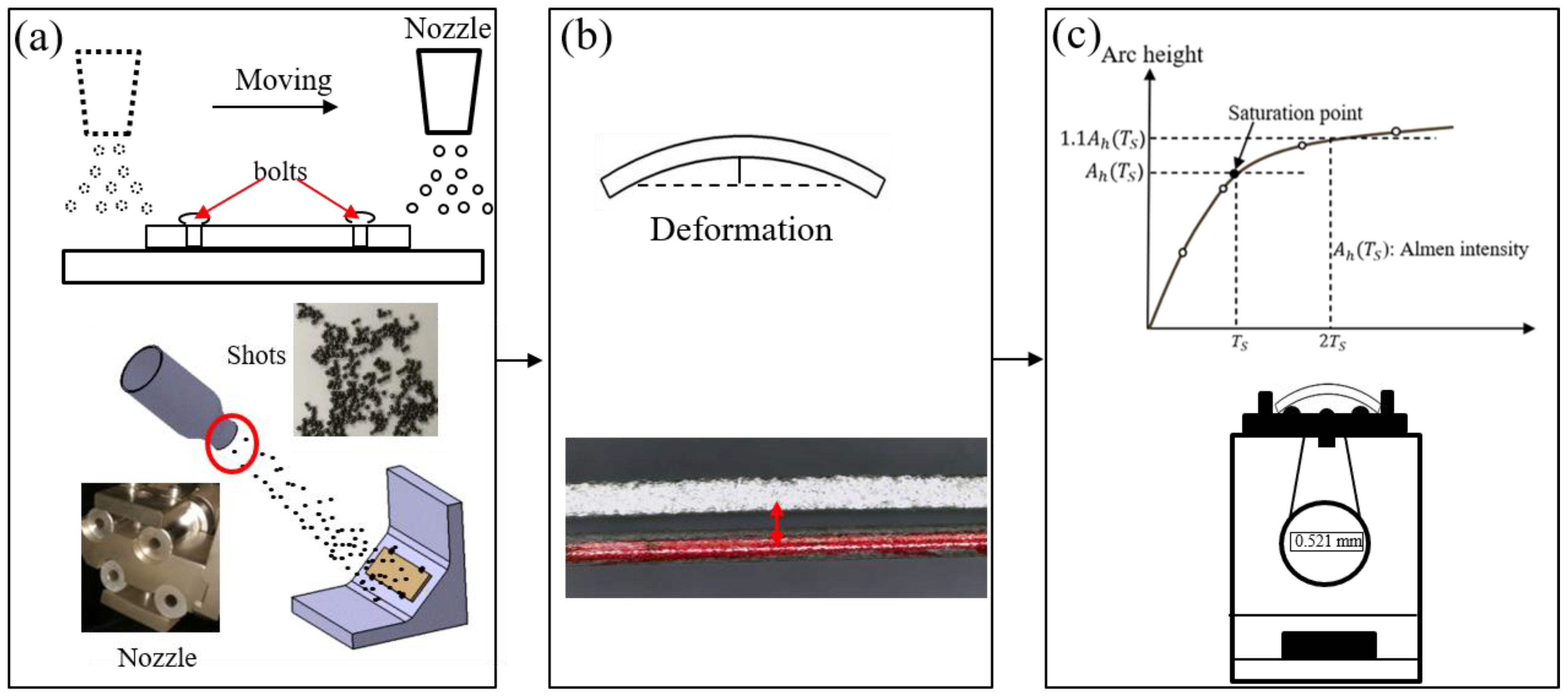
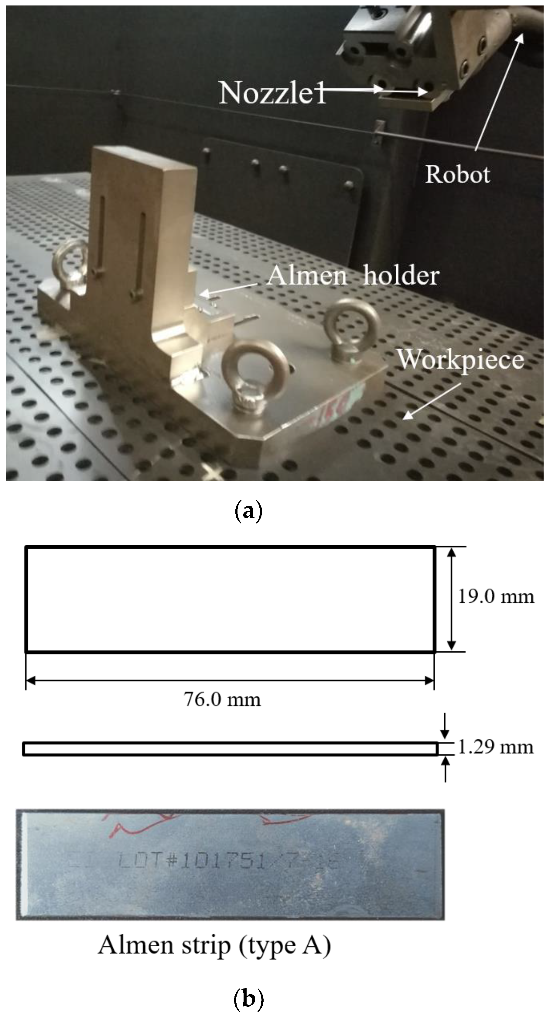
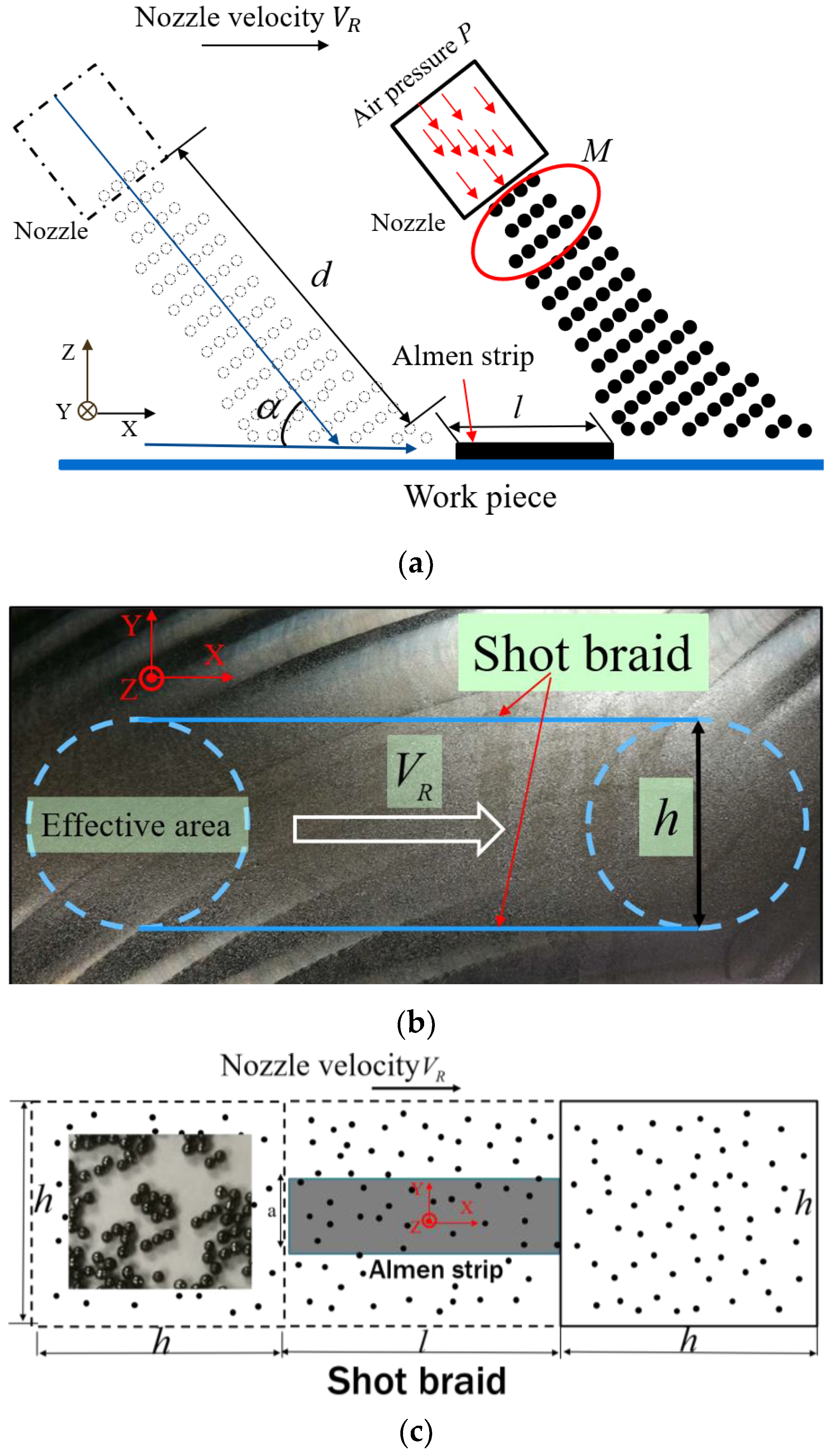
2.1. Shot Peening Experiment
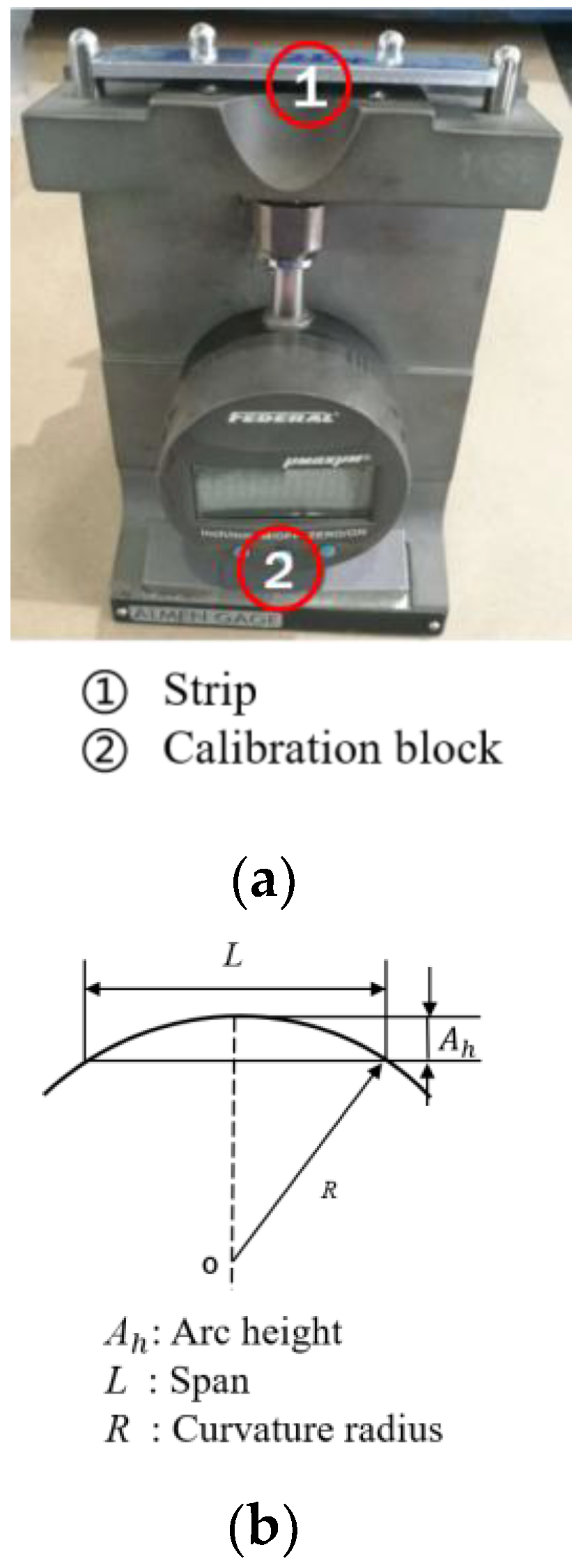
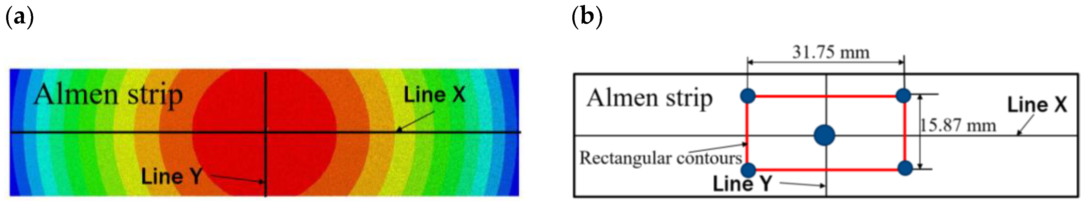
2.2. Measuring Arc Height
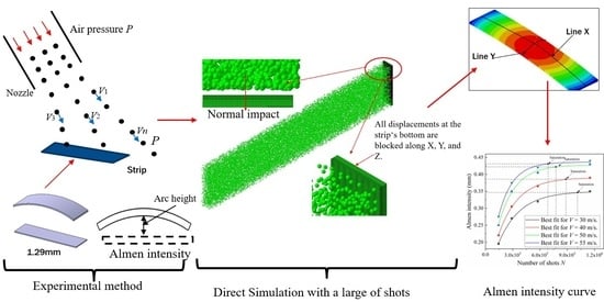
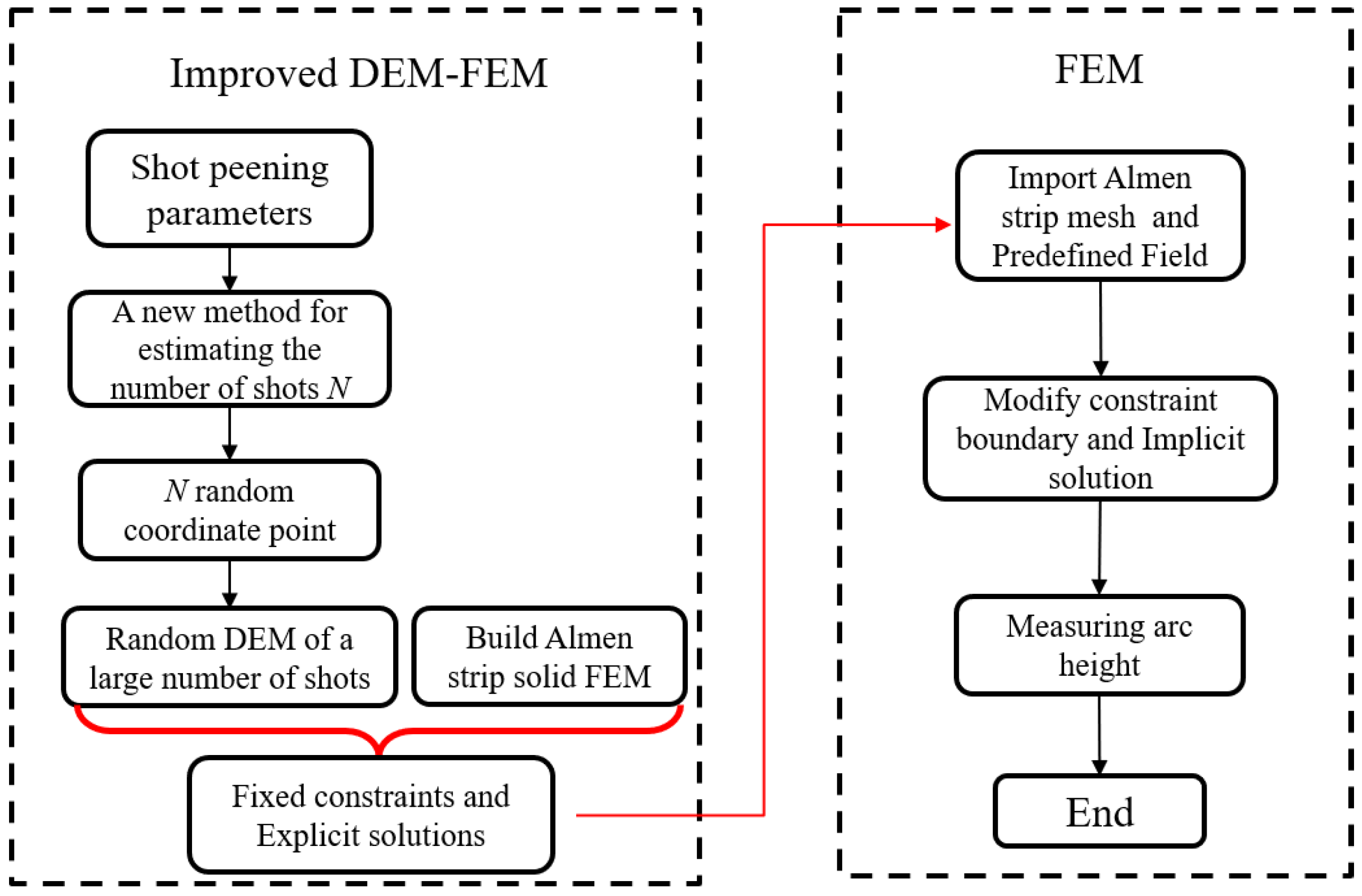
3. The Improved DEM–FEM Approach
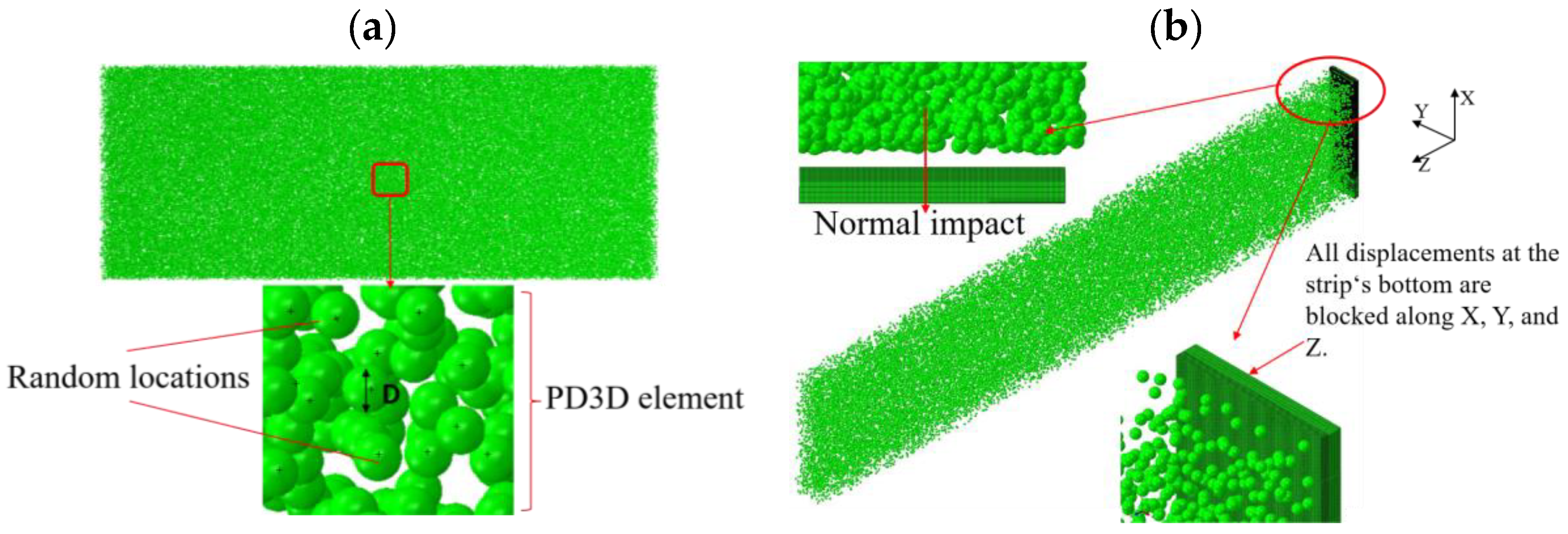
3.1. Overall Strategy
3.2. Material Model
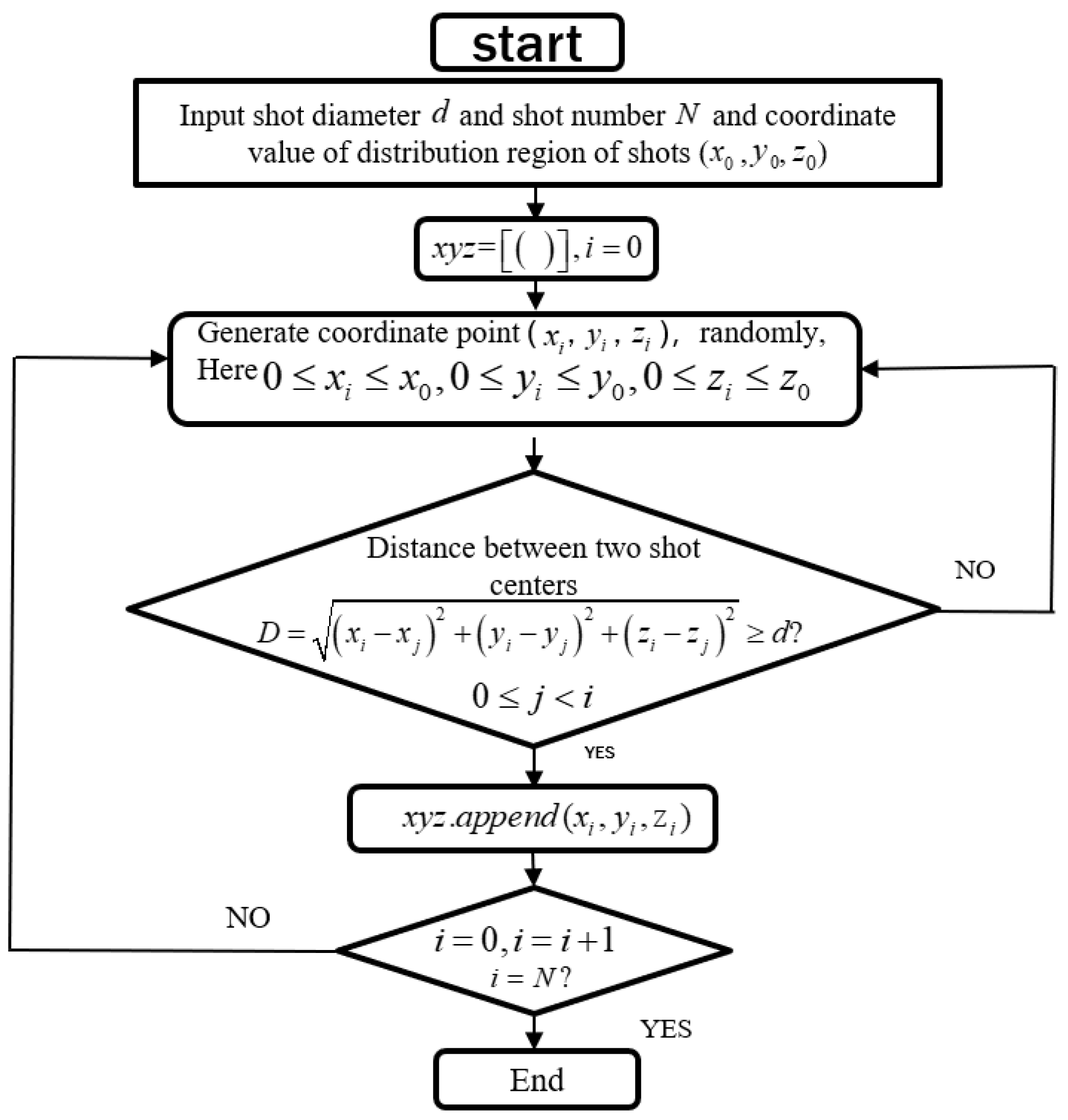
3.3. A New Method for Calculating the Shot Stream Number
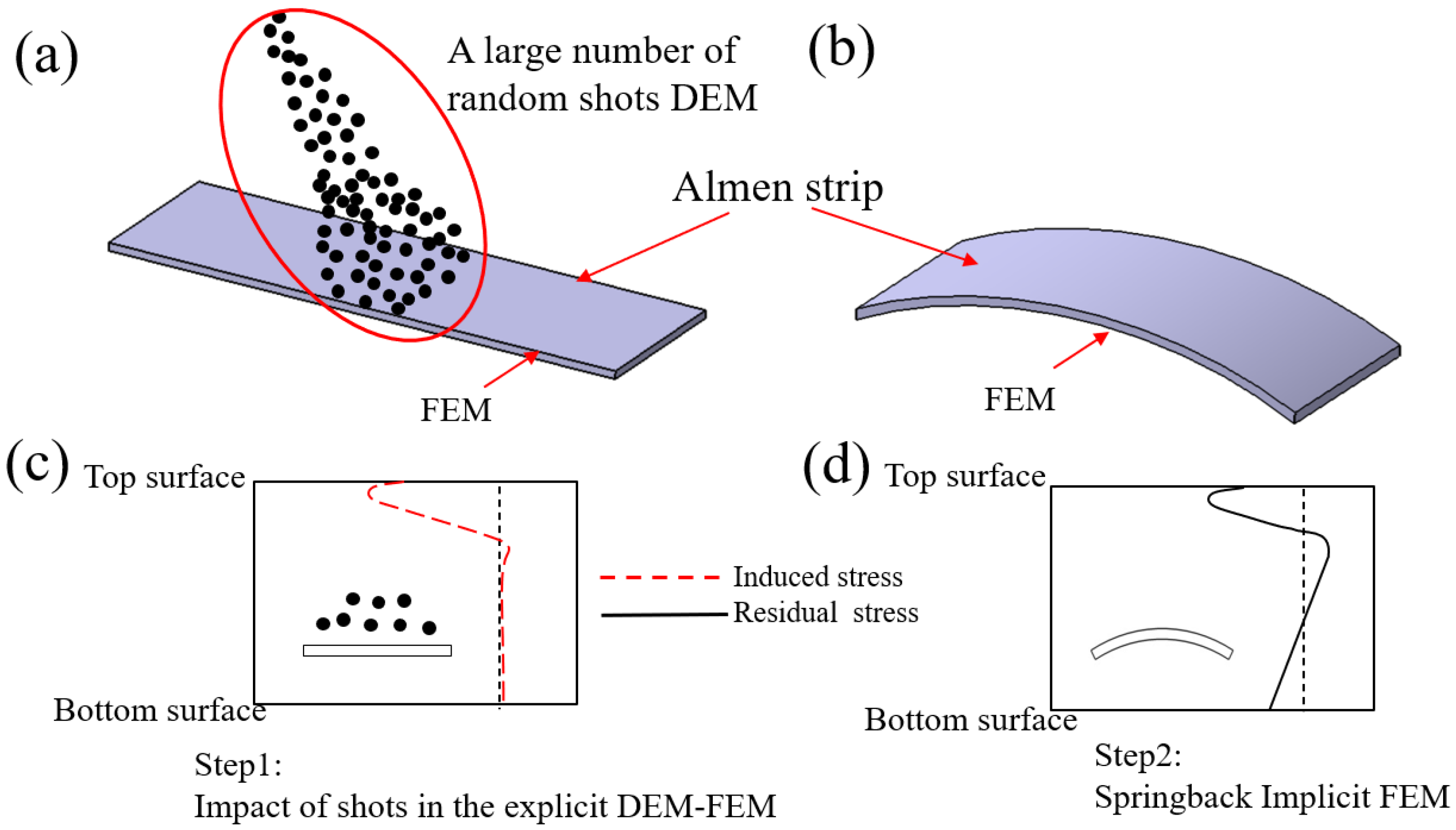
3.4. Improved DEM–FEM Approach
3.4.1. The First Model: Improved DEM–FEM for Impacting
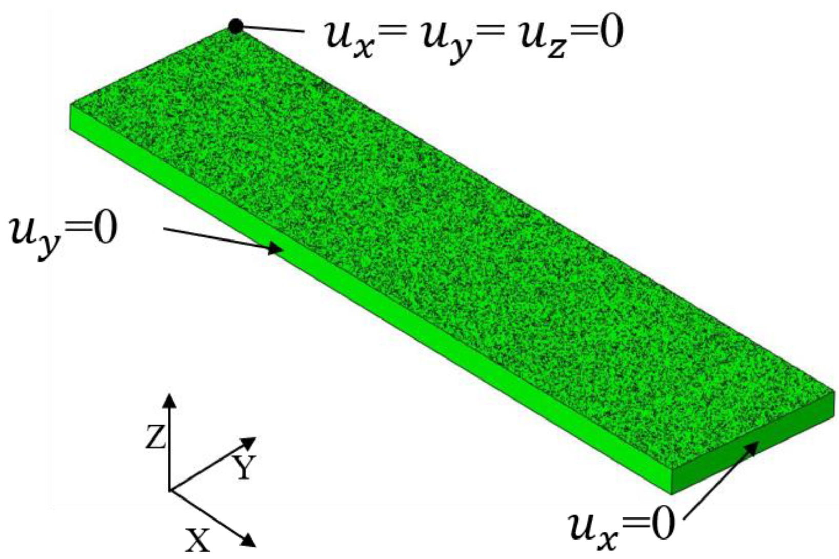
3.4.2. The Second Model: Springback Implicit FEM for Removal Constraints
4. Results
4.1. Almen Intensity and Arc Height
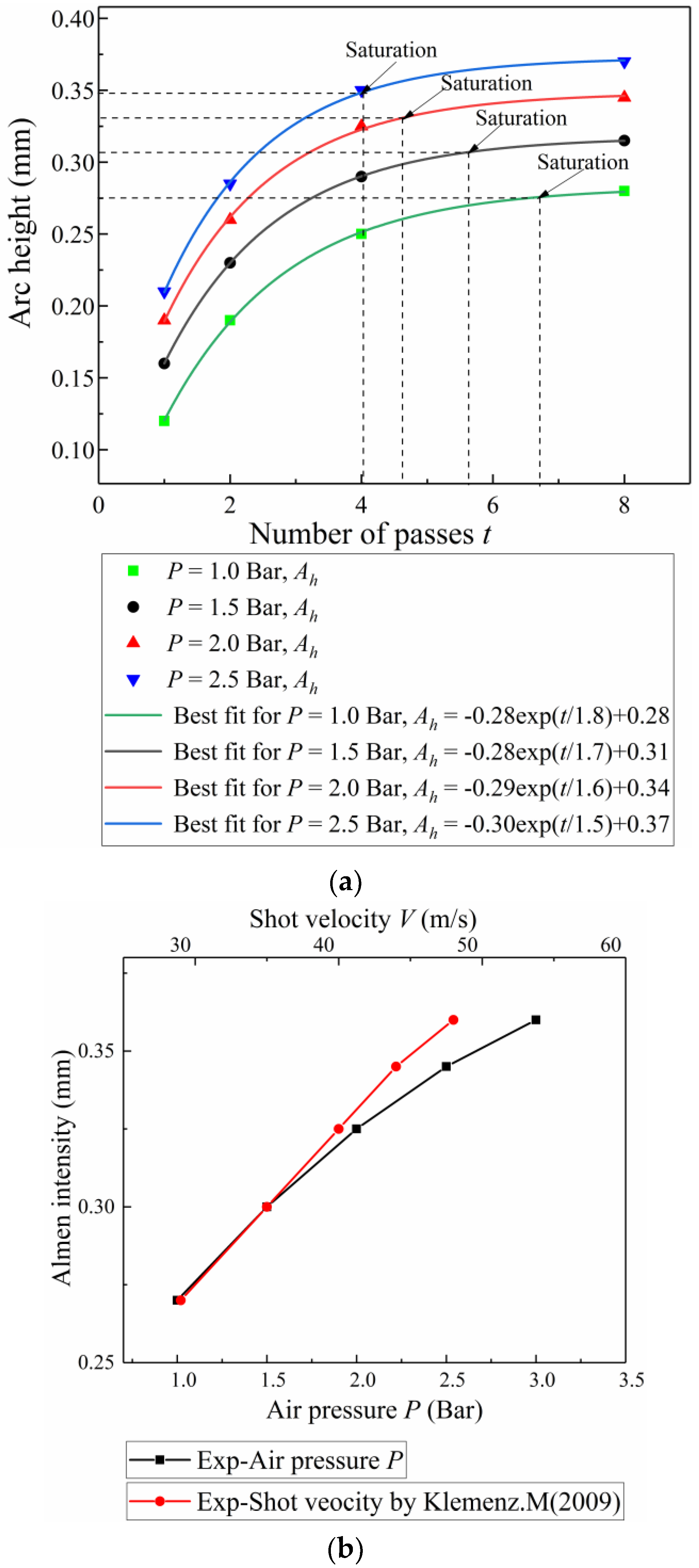
4.1.1. Experimental Measures
4.1.2. Simulation Results
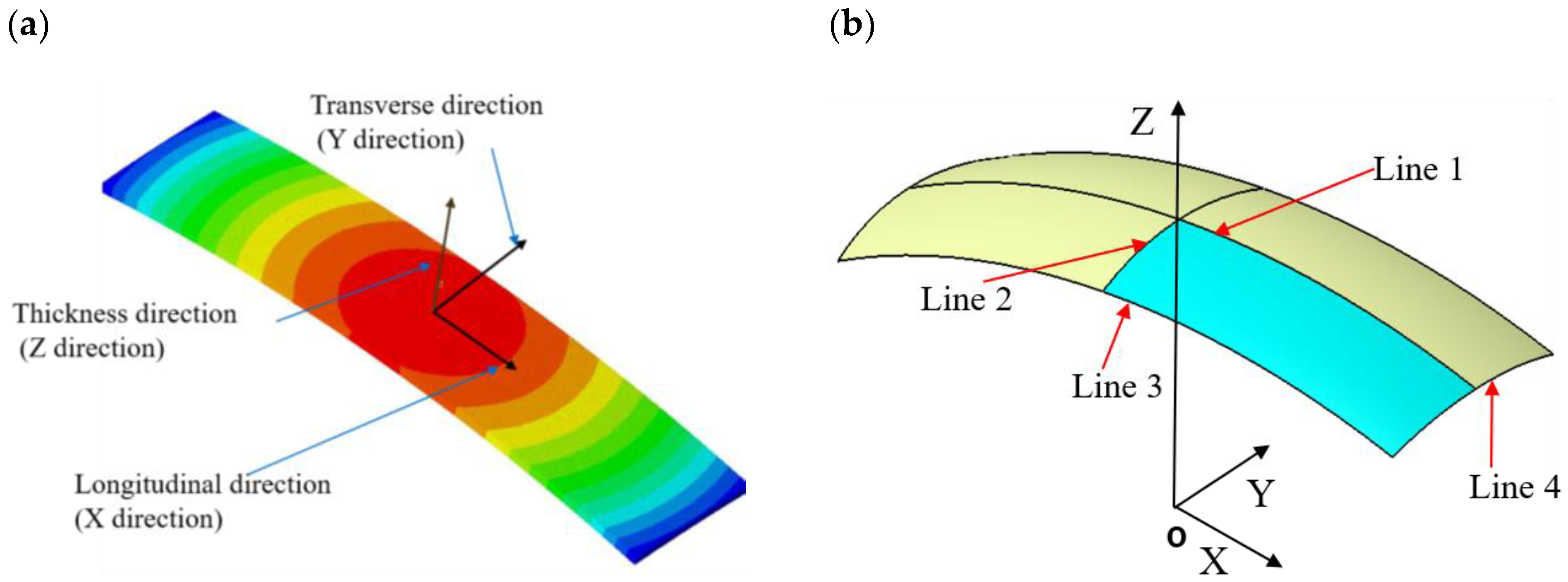
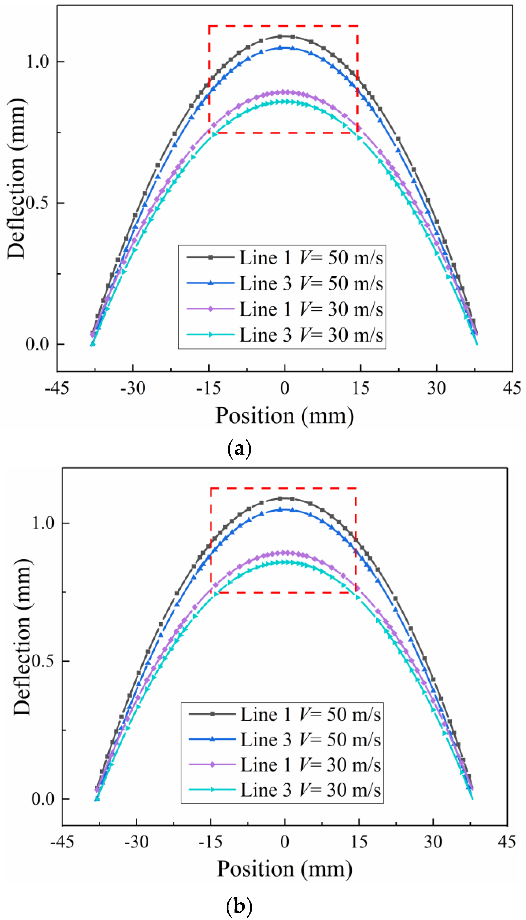
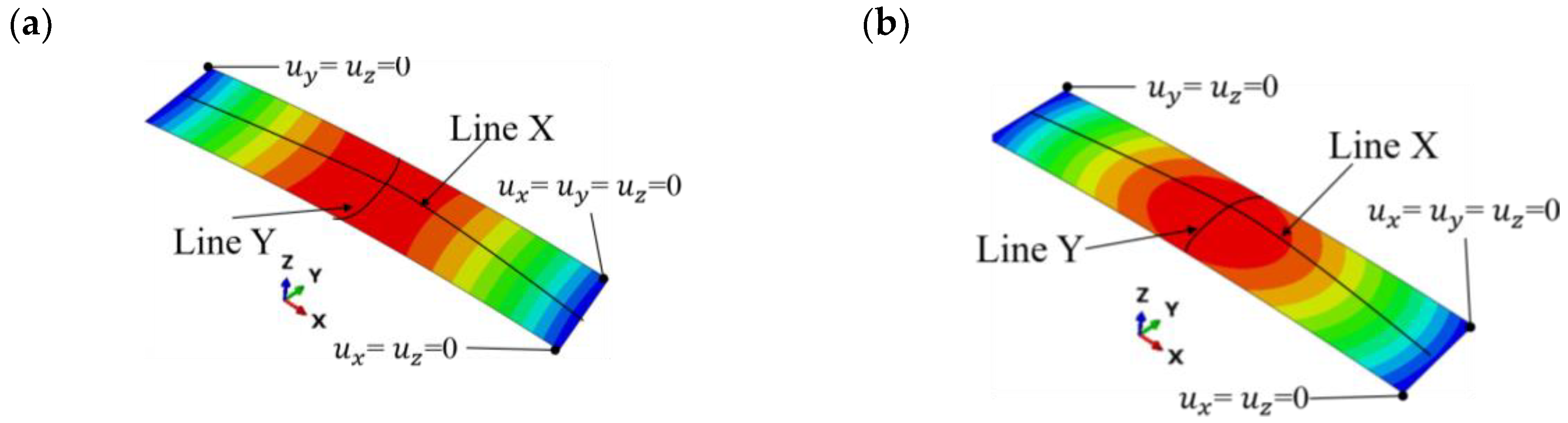
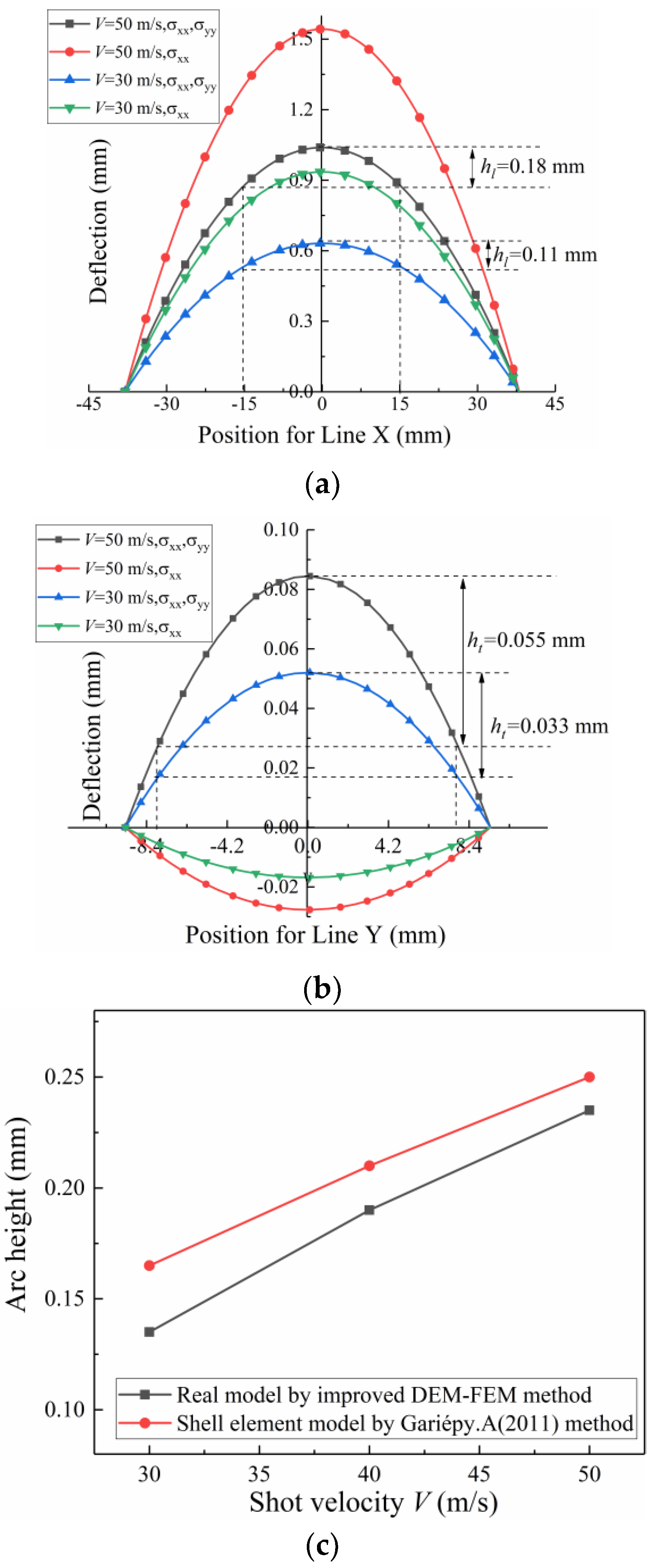
(1) Deformation Characteristics
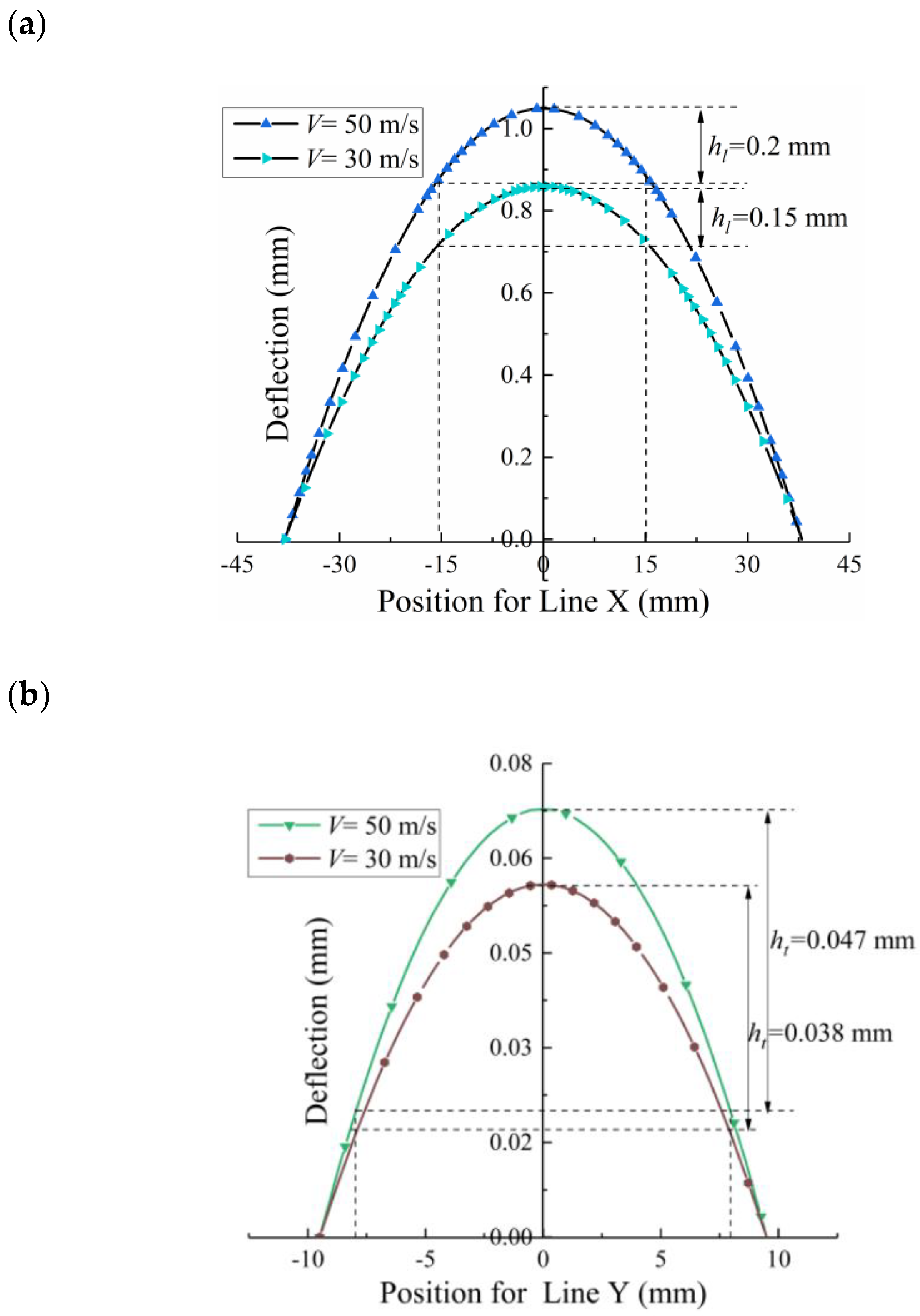
(2) Arc Height
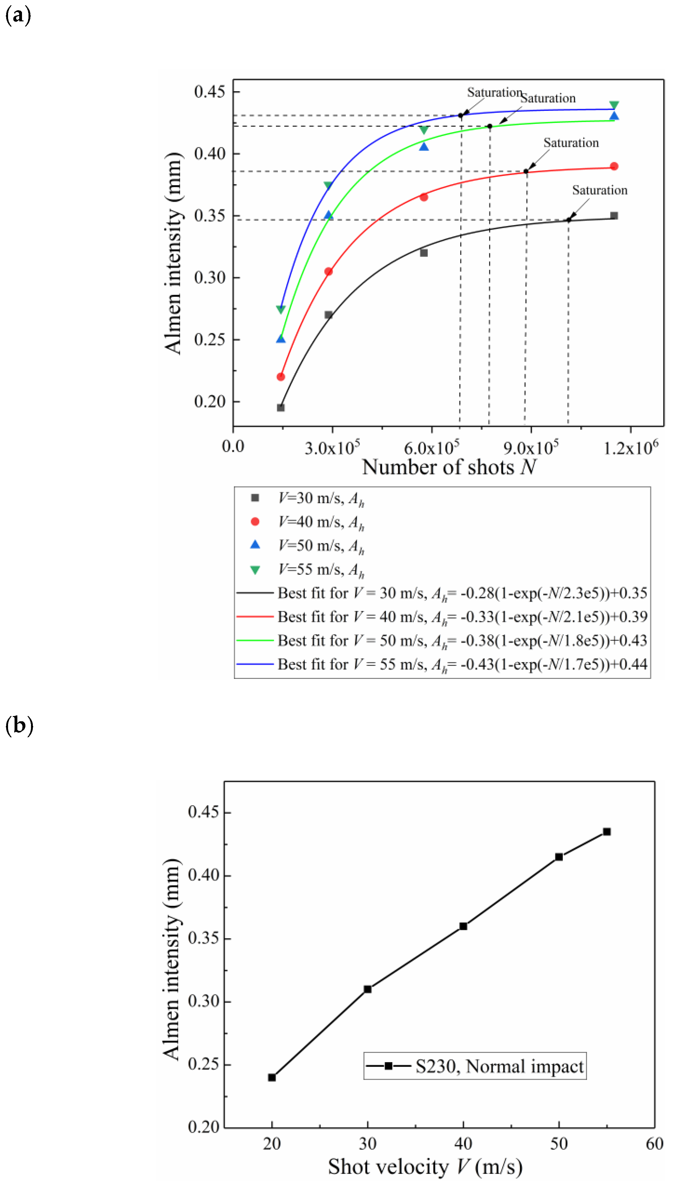
(3) Almen Intensity
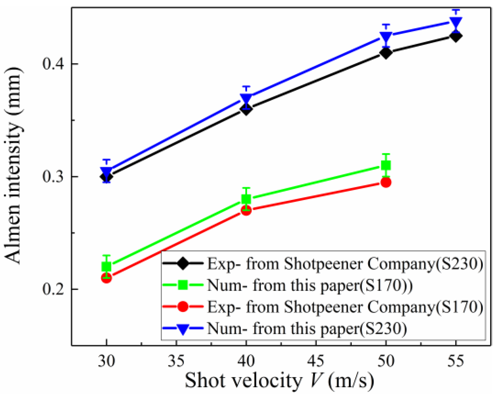
4.2. Validation
4.2.1. Almen Intensity Validation
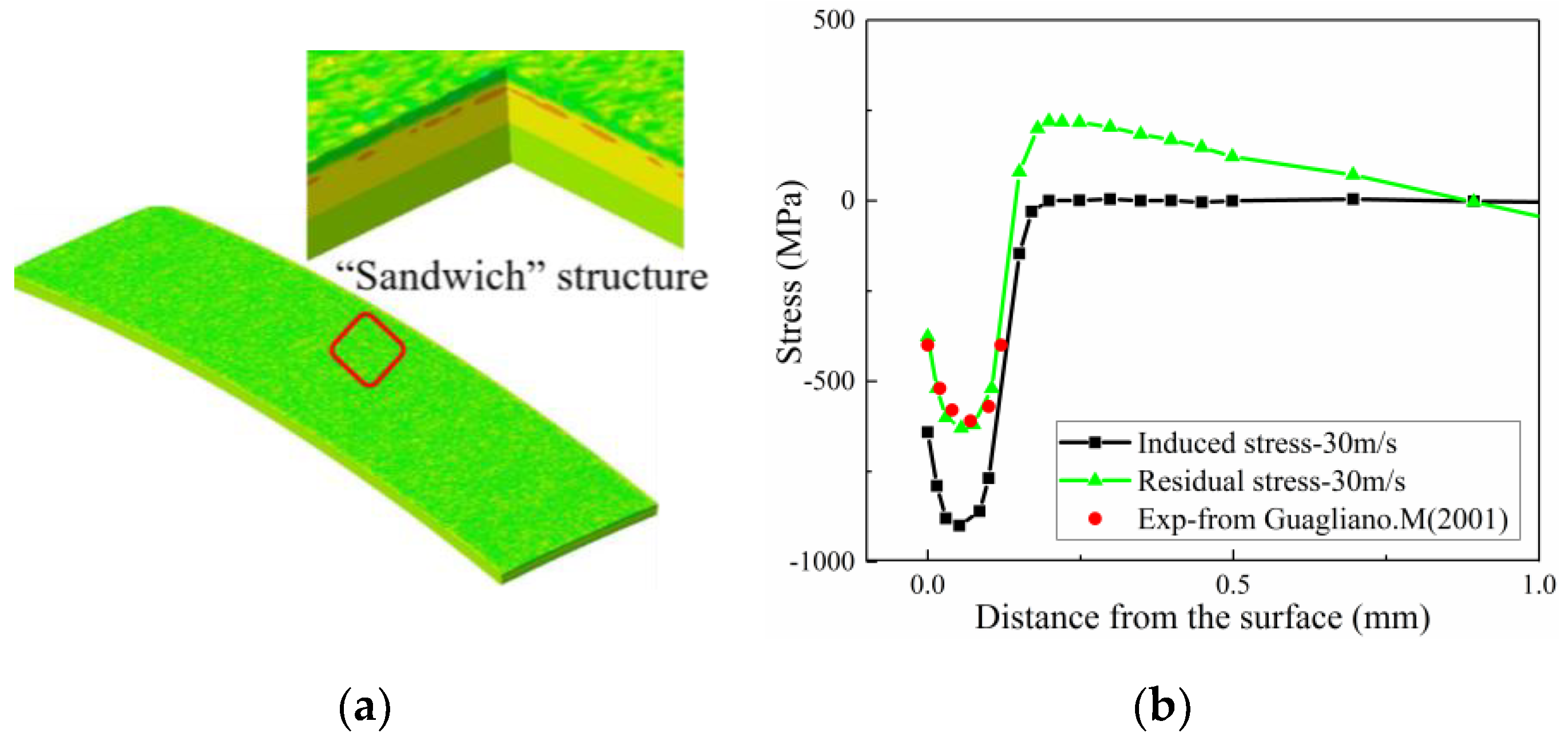
4.2.2. Residual Stress Validation
5. Discussion
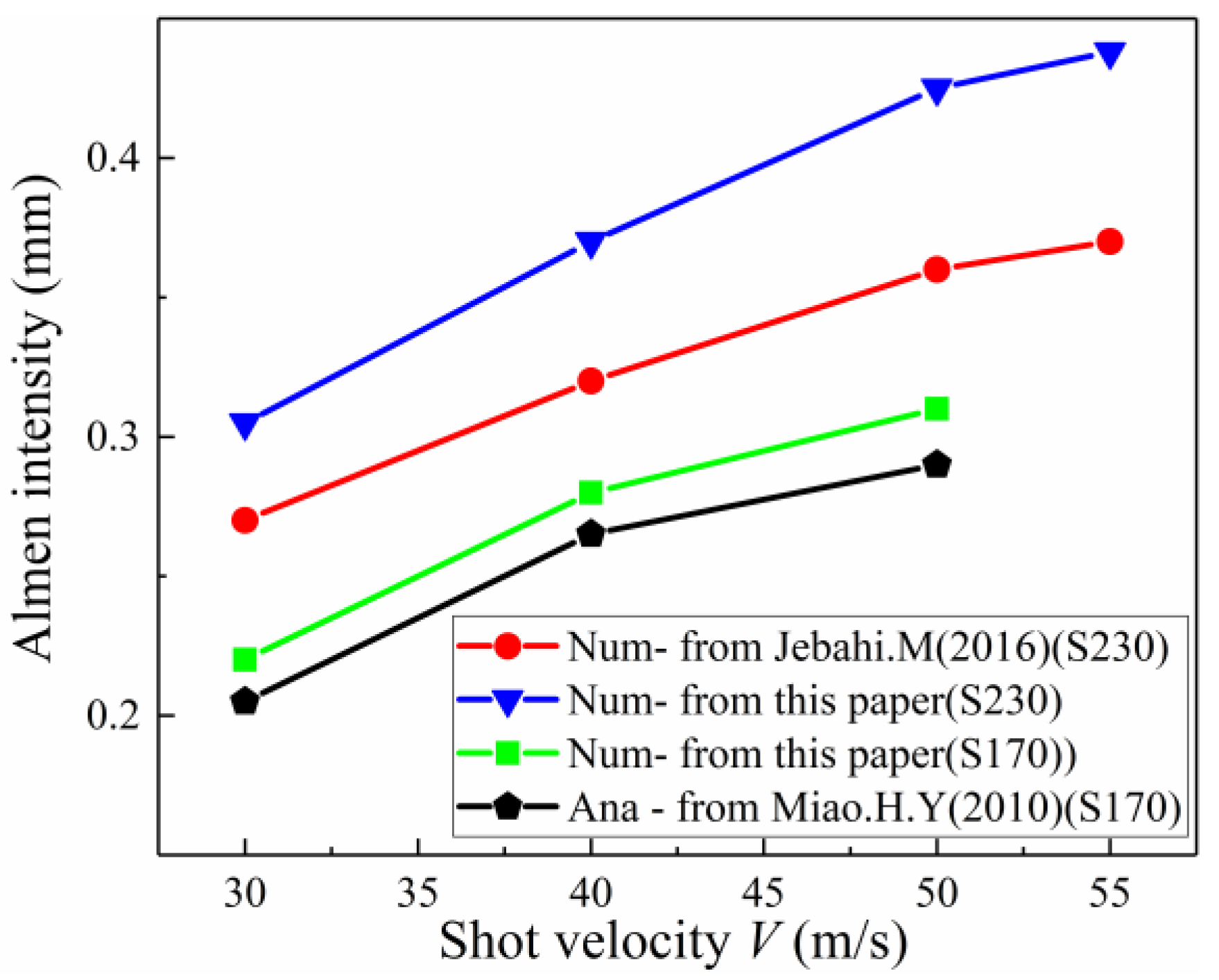
5.1. Comparison Study of Almen Intensity by Improved DEM-FEM Method and Other Existing Methods
- (1)
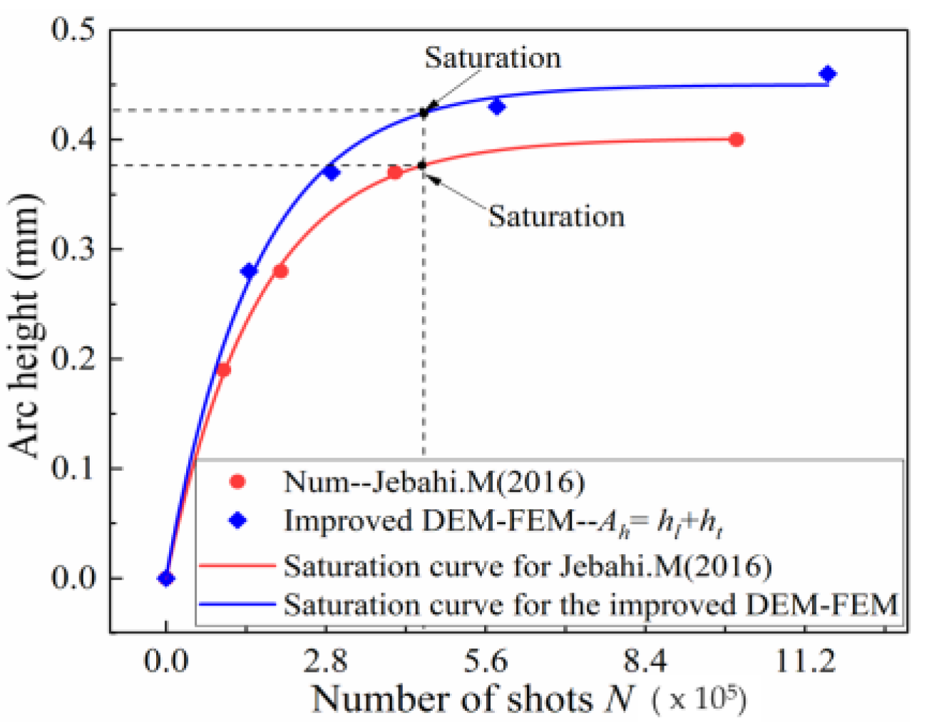
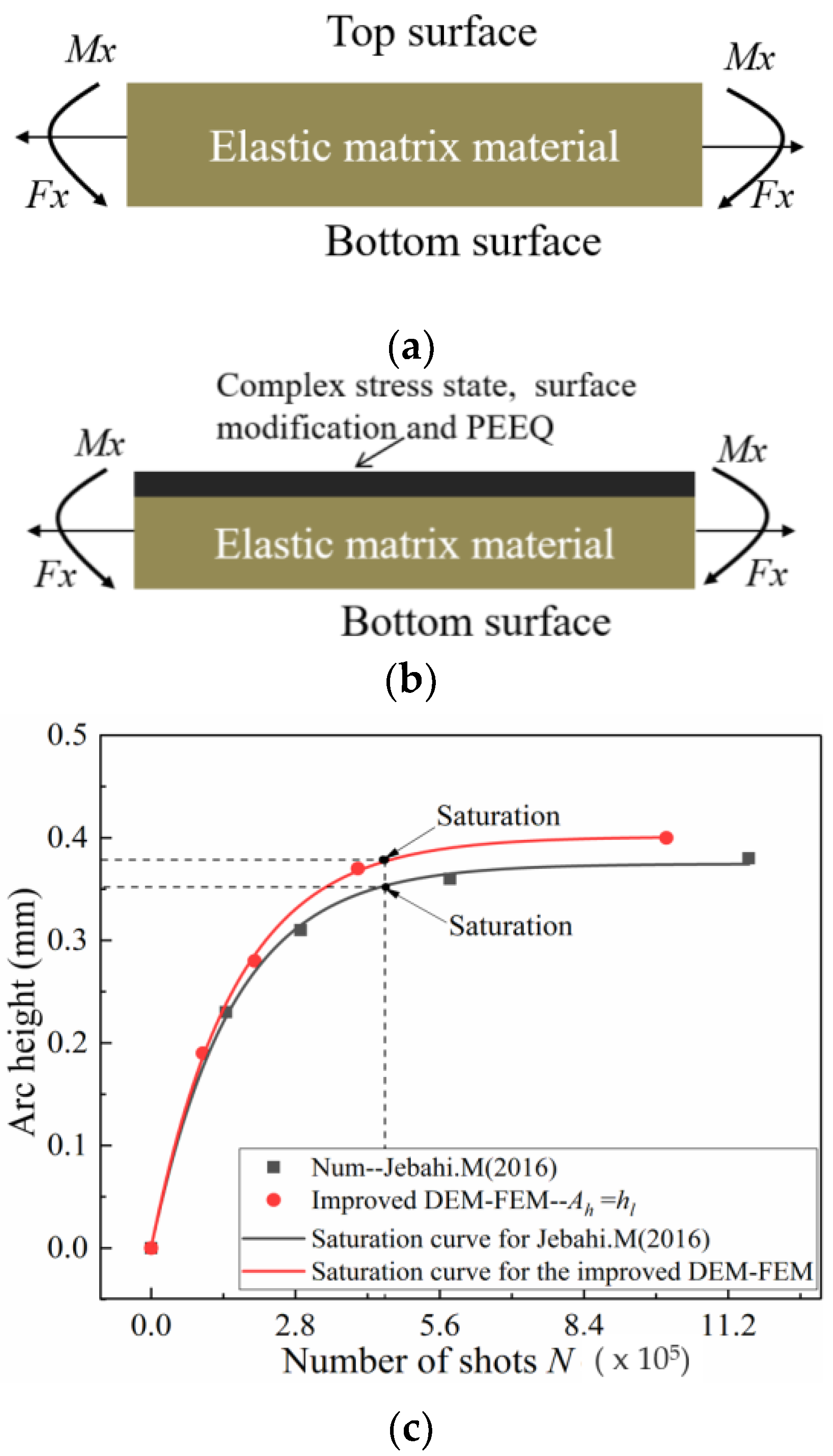
- One of the main factors affecting the accuracy of arc height is transverse deformation. The transverse deformation of the strips, however, is often neglected when existing methods are used to obtain the arc height. For example, Jebahi and Gakwaya [15] used a numerical method and elastic theory to calculate arc height and ignored the effect of transverse deformation. Figure 19 shows that the saturation curve obtained by the improved method in this paper is obviously more than that obtained by Jebahi and Gakwaya [15]. Although transverse bending is smaller in the relative longitudinal direction than in other directions, its contribution to the total arc height is not small and should not be neglected. The transverse arc height is approximately one-fifth of the total arc height.
- (2)
- Another of the main factors affecting the accuracy of arc height is the plastic layer. The real Almen strip solid element model is used instead of the representative unit, shell element and other equivalent models in this paper. The PEEQ, complex stress state, and surface morphology on the surface of the real Almen strip model are inherited by the Springback model. Moreover, for the existing method, the material model for calculating arc height is still the same elastic constitutive model as the material model before shot peening. However, the effect of surface hardening due to shot peening is not considered, as shown in Figure 20a. In fact, the residual stress, PEEQ and surface roughness on the surface of the real Almen strip are the mechanisms for improving the fatigue life after shot peening, as shown in Figure 20b. Ongtrakulkij and Khantachawana [28] reported that shot peening is a surface modification that can increase the bending strength by increasing the hardness and residual compressive stress. Bhuvaraghan and Srinivasan [4] proposed that the unit cell approach without superposition of the elastic theory is likely to provide accurate results when the thickness is high compared to the thickness of the plastic layer. It can be concluded that the surface morphology, complex stress state, and PEEQ of the plastic hardening layer influence the deformation of the strip. The saturation point obtained by the improved method in this paper and ignoring transverse deformation is slightly more than that obtained by Jebahi, Gakwaya et al. (2016), as shown in Figure 20c. This difference may be explained by the fact that PEEQ, the complex stress state and surface morphology of the plastic hardening layer decrease the bending stiffness of the strip. The influence of the plastic layer on deformation is about 10%. Currently, it is clear how the plastic hardening layer affects the arc height, and this factor should not be ignored. The proposed improved DEM-FEM approach can avoid this problem by considering the surface morphology, complex stress state, and PEEQ naturally.
5.2. Comparison Study of Arc Height by Improved DEM-FEM Method and Existing Shell Element Method
6. Conclusions
- (1)
- Direct simulation of the Almen intensity test by a real and large number of shots is proposed and then implemented for the first time. The deformation of the Almen strip is modeled using the springback implicit FEM to accurately model the mechanical response in terms of deformation. The arc height of the Almen strip is directly obtained after the removal of the bottom constraint, rather than by the equivalent method. Therefore, the method proposed in this paper is closer to the real shot peening process. Though the computational effort involved in this simulation may be higher than the traditional method, it is now possible to obtain the Almen intensity without using any post-analysis corrections.
- (2)
- The existing simulation method is mainly to calculate the number of shots by means of coverage rate, but this method cannot reflect the process parameters in the actual shot peening process. A new method for calculating the number of shots needed for simulation based on experiments and process parameters such as the mass flowrate, nozzle movement speed and nozzle–workpiece distance is presented in this paper, and a formula for calculating the number of shots is derived. This new method is used to calculate the number of shots and then to link the shot peening experiment and simulation.
- (3)
- The simulation results and experimental results show that the transverse deformation cannot be ignored when calculating the arc height; the transverse arc height is approximately one-fifth of the total arc height. The influence of the surface plastic layer on the deformation of the Almen strip should be considered; the influence of the plastic layer on deformation is about 10%. The method presented in this paper naturally takes the transverse deformation and surface plastic layer into account. Thus, the Almen intensity calculated by the direct simulation method therefore is in better agreement with the experimental results and literature data than that calculated by existing methods.
Author Contributions
Funding
Acknowledgments
Conflicts of Interest
References
- Wu, J.; Liu, H.; Wei, P.; Lin, Q.; Zhou, S. Effect of shot peening coverage on residual stress and surface roughness of 18CrNiMo7-6 steel. Int. J. Mech. Sci. 2020, 183, 105785. [Google Scholar] [CrossRef]
- Xiao, X.D.; Tong, X.; Li, Y.; Wei, S.; Gao, G. Analysis of stress increment in shot peen forming weak-stiffness component. Int. J. Adv. Manuf. Technol. 2018, 94, 4039–4053. [Google Scholar] [CrossRef]
- Zhan, C.; Yang, W. A high efficient surface-based method for predicting part distortions in machining and shot peening. Int. J. Mech. Sci. 2016, 119, 125–143. [Google Scholar] [CrossRef]
- Bhuvaraghan, B.; Srinivasan, S.M.; Maffeo, B. Numerical simulation of Almen strip response due to random impacts with strain-rate effects. Int. J. Mech. Sci. 2011, 53, 417–424. [Google Scholar] [CrossRef]
- Gariépy, A.; Larose, S.; Perron, C.; Bocher, P.; Levesque, M. On the effect of the orientation of sheet rolling direction in shot peen forming. J. Mater. Proc. Technol. 2013, 213, 926–938. [Google Scholar] [CrossRef]
- Miao, H.Y.; Demers, D.; Larose, S.; Perron, C.; Levesque, M. Experimental study of shot peening and stress peen forming. J. Mater. Proc. Technol. 2010, 210, 2089–2102. [Google Scholar] [CrossRef]
- Kumar, R.K.; SampathKumaran, P.; Seetharamu, S.; Kumar, S.A.; Pramod, T.; Naveen, G.J. Investigation of Shot Peening Effect on Titanium Alloy Affecting Surface Residual Stress and Roughness for Aerospace Applications. Proced. Struct. Integr. 2019, 14, 134–141. [Google Scholar] [CrossRef]
- Miao, H.Y.; Larose, S.; Perron, C.; Levesque, M. An analytical approach to relate shot peening parameters to Almen intensity. Surf. Coat. Technol. 2010, 205, 2055–2066. [Google Scholar] [CrossRef]
- Zhang, X.J.; Wang, T.; Wang, J.B.; Liu, C. Analytical modeling of shot peen forming process using cross-sectional linear indentation coverage method. Int. J. Mech. Sci. 2017, 133, 838–845. [Google Scholar] [CrossRef]
- Sherafatnia, K.; Farrahi, G.H.; Mahmoudi, A.H.; Ghasemi, A. Experimental measurement and analytical determination of shot peening residual stresses considering friction and real unloading behavior. Mater. Sci. Eng. A Struct. Mater. Prop. Microstruct. Proc. 2016, 657, 309–321. [Google Scholar] [CrossRef]
- Xiao, X.D.; Tong, X.; Liu, Y.; Zhao, R.; Gao, G.; Li, Y. Prediction of shot peen forming effects with single and repeated impacts. Int. J. Mech. Sci. 2018, 137, 182–194. [Google Scholar] [CrossRef]
- Marini, M.; Piona, F.; Fontanari, V.; Bandini, M.; Benedetti, M. A new challenge in the DEM/FEM simulation of the shot peening process: The residual stress field at a sharp edge. Int. J. Mech. Sci. 2020, 169, 105327. [Google Scholar] [CrossRef]
- Tu, F.; Delbergue, D.; Miao, H.; Klotz, T.; Brochu, M.; Bocher, P.; Levesque, M. A sequential DEM-FEM coupling method for shot peening simulation. Surf. Coat. Technol. 2017, 319, 200–212. [Google Scholar] [CrossRef]
- Murugaratnam, K.; Utili, S.; Petrinic, N. A combined DEM–FEM numerical method for Shot Peening parameter optimisation. Adv. Eng. Software 2015, 79, 13–26. [Google Scholar] [CrossRef]
- Jebahi, M.; Gakwaya, A.; Levesque, J.; Mechri, O.; Ba, K. Robust methodology to simulate real shot peening process using discrete-continuum coupling method. Int. J. Mech. Sci. 2016, 107, 21–33. [Google Scholar] [CrossRef]
- Guagliano, M. Relating Almen intensity to residual stresses induced by shot peening: A numerical approach. J. Mater. Proc. Technol. 2001, 110, 277–286. [Google Scholar] [CrossRef]
- Han, K.; Owen, D.R.J.; Peric, D. Combined finite/discrete element and explicit/implicit simulations of peen forming process. Eng. Comput. 2002, 19, 92–118. [Google Scholar] [CrossRef]
- Wang, T.; Platts, M.J.; Levers, A. A process model for shot peen forming. J. Mater. Proc. Technol. 2006, 172, 159–162. [Google Scholar] [CrossRef]
- Gariépy, A.; Cyr, J.; Levers, A.; Perron, C.; Bocher, P.; Levesque, M. Potential applications of peen forming finite element modelling. Adv. Eng. Software 2012, 52, 60–71. [Google Scholar] [CrossRef]
- Miao, H.Y.; Larose, S.; Perron, C.; Levesque, M. Numerical simulation of the stress peen forming process and experimental validation. Adv. Eng. Software 2011, 42, 963–975. [Google Scholar] [CrossRef]
- Edward, A.B.; Heyns, P.S.; Pietra, F. Shot Peening Modeling and Simulation for RCS Assessment. Proc. Manuf. 2017, 7, 172–177. [Google Scholar] [CrossRef]
- Hu, Y.; Zhang, W.; Jiang, W.; Cao, L.; Shen, Y.; Li, H.; Guan, Z.; Tao, J.; Xu, J. Effects of exposure time and intensity on the shot peen forming characteristics of Ti/CFRP laminates. Compos. Part A Appl. Sci. Manuf. 2016, 91, 96–104. [Google Scholar] [CrossRef]
- Zhang, J.B.; Lu, S.; Zhou, Z.; Wu, T.; Xu, G. Modeling of multiple shots for analyzing shot peening controlled parameters on formed curvature radius. Int. J. Adv. Manuf. Technol. 2017, 93, 1867–1876. [Google Scholar] [CrossRef]
- Huang, H.; Wang, Z.; Gan, J.; Yang, Y.; Wang, X.; He, J.; Gan, X. The study of universality of a method for predicting surface nanocrystallization after high energy shot peening based on finite element analysis. Surf. Coat. Technol. 2019, 358, 617–627. [Google Scholar] [CrossRef]
- Mohamed, A.L.M.O.; Farhat, Z.; Warkentin, A.; Gillis, J. Effect of a moving automated shot peening and peening parameters on surface integrity of Low carbon steel. J. Mater. Proc. Technol. 2020, 277, 116399. [Google Scholar] [CrossRef]
- Klemenz, M. Der Simulation der Randschichtausbildung beim Kugelstrahlen auf die Abschätzung der Schwingfestigkeit Gekerbter Bauteile. Ph.D. Thesis, Universität Karlsruhe, Shaker, Aachen, 2009. [Google Scholar]
- Shotpeenercompany. Shot Size and Speed to Achieve Almen Intensity. Available online: http://www.shotpeener.com/learning/ref.php (accessed on 11 November 2020).
- Ongtrakulkij, G.; Khantachawana, A.; Kondoh, K. Effects of media parameters on enhance ability of hardness and residual stress of Ti6Al4V by fine shot peening. Surf. Interfaces 2020, 18, 100424. [Google Scholar] [CrossRef]
- Gariépy, A.; Larose, S.; Perron, C.; Levesque, M. Shot peening and peen forming finite element modelling—Towards a quantitative method. Int. J. Solids Struct. 2011, 48, 2859–2877. [Google Scholar] [CrossRef]


| Mechanical Properties | Johnson–Cook Constants | |||||||
|---|---|---|---|---|---|---|---|---|
| Material | E (GPa) | ν | ρ (kg/m3) | A (MPa) | B (MPa) | C | n | m |
| Shot (Stainless steel) | 210 | 0.3 | 7850 | |||||
| Almen strip (SAE 1070) | 205 | 0.29 | 7800 | 1048 | 600.8 | 0.0134 | 0.234 | 0 |
| Case | VR (mm/min) | T | N |
|---|---|---|---|
| Strip 1 | 1000 | 1 | 144,000 |
| Strip 2 | 1000 | 2 | 288,000 |
| Strip 3 | 1000 | 4 | 576,000 |
| Strip 4 | 1000 | 8 | 1,150,000 |
| W | P | |||
|---|---|---|---|---|
| 1.0 | 1.5 | 2.0 | 2.5 | |
| 1 | 0.11 | 0.13 | 0.17 | 0.23 |
| 2 | 0.15 | 0.18 | 0.22 | 0.27 |
| 4 | 0.19 | 0.22 | 0.26 | 0.32 |
| 8 | 0.20 | 0.24 | 0.28 | 0.33 |
Publisher’s Note: MDPI stays neutral with regard to jurisdictional claims in published maps and institutional affiliations. |
© 2020 by the authors. Licensee MDPI, Basel, Switzerland. This article is an open access article distributed under the terms and conditions of the Creative Commons Attribution (CC BY) license (http://creativecommons.org/licenses/by/4.0/).
Share and Cite
Wang, C.; Li, W.; Jiang, J.; Chao, X.; Zeng, W.; Xu, J.; Yang, J. An Improved Approach to Direct Simulation of an Actual Almen Shot Peening Intensity Test with a Large Number of Shots. Materials 2020, 13, 5088. https://doi.org/10.3390/ma13225088
Wang C, Li W, Jiang J, Chao X, Zeng W, Xu J, Yang J. An Improved Approach to Direct Simulation of an Actual Almen Shot Peening Intensity Test with a Large Number of Shots. Materials. 2020; 13(22):5088. https://doi.org/10.3390/ma13225088
Chicago/Turabian StyleWang, Chengyu, Weigang Li, Jianjun Jiang, Xin Chao, Weikui Zeng, Jiang Xu, and Jie Yang. 2020. "An Improved Approach to Direct Simulation of an Actual Almen Shot Peening Intensity Test with a Large Number of Shots" Materials 13, no. 22: 5088. https://doi.org/10.3390/ma13225088
APA StyleWang, C., Li, W., Jiang, J., Chao, X., Zeng, W., Xu, J., & Yang, J. (2020). An Improved Approach to Direct Simulation of an Actual Almen Shot Peening Intensity Test with a Large Number of Shots. Materials, 13(22), 5088. https://doi.org/10.3390/ma13225088