Pre-Machining of Rolled Plates as an Element of Minimising the Post-Machining Deformations


Abstract
1. Introduction
- Technological parameters, i.e., depth of cut, feed, cutting speed;
- Cutting tool geometry;
- Cooling conditions;
- Properties of the machined material;
- Degree of the cutting tool wear.
2. Materials and Methods
- High-performance cutting;
- High-performance cutting and conventional milling (CM);
- High-performance cutting and high-speed cutting;
- High-speed cutting;
- High-speed cutting and conventional milling (CM).
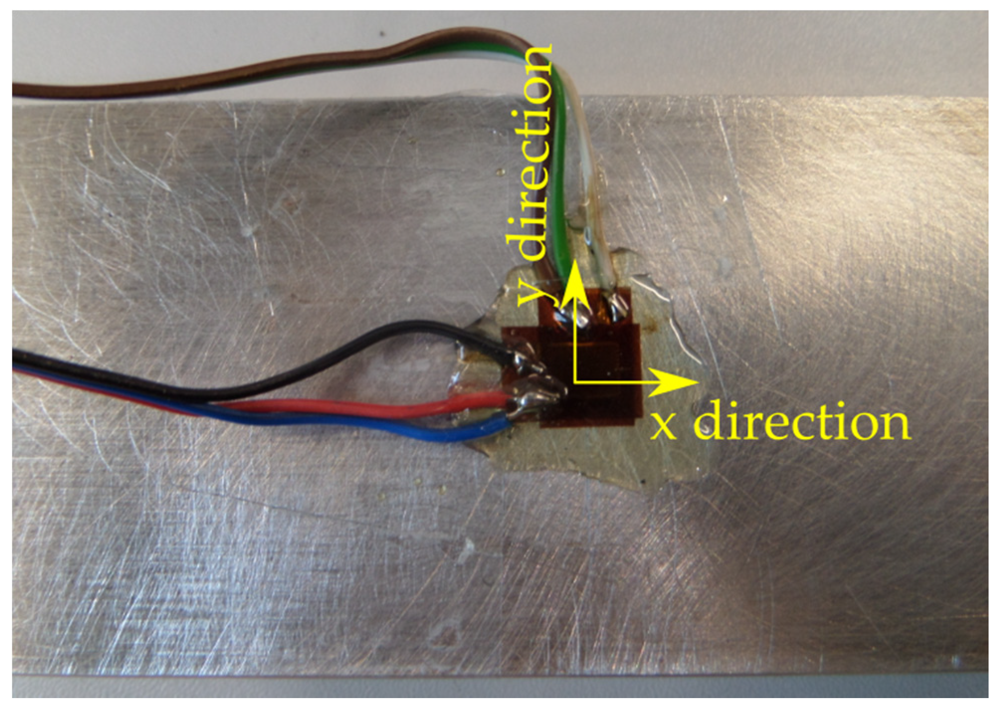
- Tool feed direction perpendicular to the rolling direction (perpendicular direction);
- Tool feed direction parallel to the rolling direction (parallel direction).
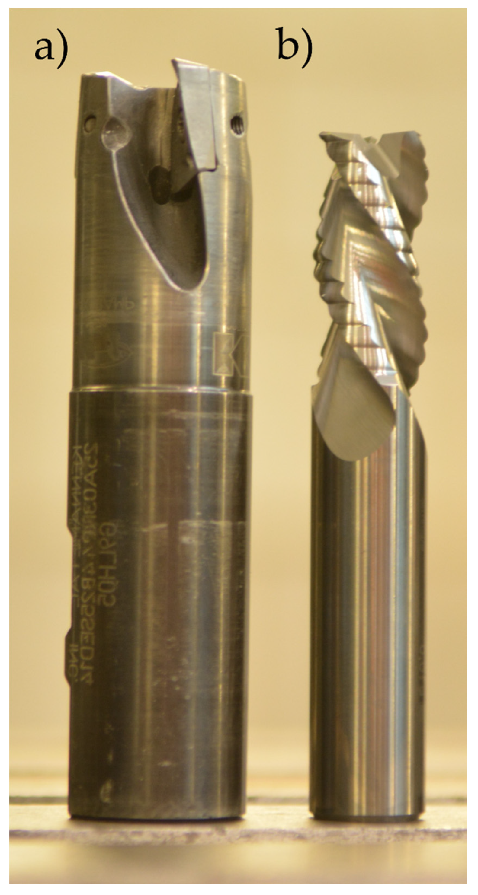
- Kennametal indexable milling cutter (25A03R044B25SED14) with adapted cutting inserts (EDCT140416PDFRLDJ) (Kennametal, Pittsburgh, PA, USA), material: KC410M—a carbide coated with TiB2 protective coating by PVD method—used for high-performance cutting (Figure 4a);
- Sandvik monolithic milling cutter (R216.33-16040-AC32U) (Sandvik, Stockholm, Sweden), material: H10F—a tungsten carbide without any protective coating—used for high-speed cutting and conventional milling (Figure 4b).
- Fastening the sample in the clamping device;
- The phase of the influence of disturbing factors (e.g., turning on the coolant oil);
- Milling process;
- Unfastening the sample from the clamping device;
- Stabilisation.
3. Results
4. Conclusions
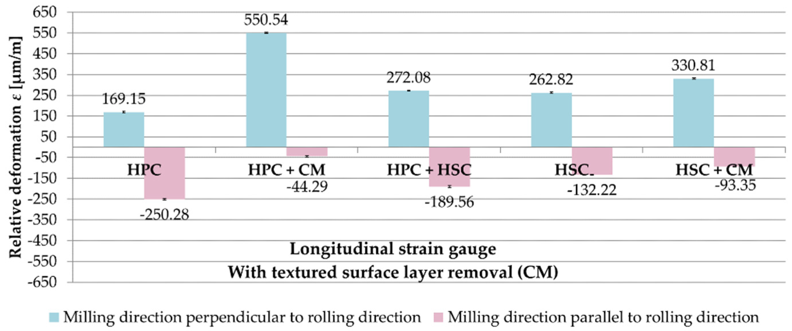
- The cutting strategy in combination with pre-machining (or lack thereof) consisting of the removal of the textured surface layer after rolling affects the relative deformation ε.
- The combination of HSC, HPC and CM has a positive effect on minimising the deformation of thin-walled elements after milling. Conventional milling, despite its relatively low efficiency, can have practical applications in the production of thin-walled elements.
- When manufacturing parts with a wall thickness of less than 2 mm, in particular less than 1 mm, removal of the rolled surface layer from the surface opposite to the machined surface, combined with the appropriate selection of a cutting strategy, can minimise post-machining deformations.
- It was found that milling direction in relation to the rolling direction on the relative deformation ε was influential. Therefore, the feed direction of the cutting tool should be parallel to the rolling direction.
- It is also necessary to remember the rational planning of supports, so as to ensure the highest possible rigidity of the workpiece in the clamping device.
- It should be emphasised that the tests were carried out on flat samples, as it was the most favourable solution to achieve the objectives of the study. For complex-shaped thin-walled structures, the stiffness is different and the deformation effects of cutting cannot be directly transferred from the flat elements’ examination.
Author Contributions
Funding
Conflicts of Interest
References
- Zębala, W. Errors minimalisation of thin-walled parts machining. Inżynieria Maszyn 2010, 3, 45–54. (In Polish) [Google Scholar]
- Singh, A.; Agrawal, A. Comparison of deforming forces, residual stresses and geometrical accuracy of deformation machining with conventional bending and forming. J. Mater. Process. Tech. 2016, 234, 259–271. [Google Scholar] [CrossRef]
- Gao, H.; Zhang, Y.; Wu, Q.; Song, J. An analytical model for predicting the machining deformation of a plate blank considers biaxial initial residual stresses. Int. J. Adv. Manuf. Tech. 2017, 93, 1473–1486. [Google Scholar] [CrossRef]
- Burakowski, T.; Wierzchoń, T. Metal Surface Engineering; Wydawnictwa Naukowo-Techniczne: Warszawa, Poland, 1995. (In Polish) [Google Scholar]
- Cheng, W.; Finnie, I. Residual Stress Measurement and the Slitting Method; Springer: Boston, MA, USA, 2007. [Google Scholar] [CrossRef]
- Shokrieh, M.M. Residual Stresses in Composite Materials; Woodhead Publishing Limited: Cambridge, UK, 2014. [Google Scholar]
- Senczyk, D. Residual Stresses-Introduction to Generation, Control and Use; Wydawnictwo Politechniki Poznańskiej: Poznan, Poland, 1996. (In Polish) [Google Scholar]
- Kartal, M.E. Analytical solutions for determining residual stresses in two-dimensional domains using the contour method. Proc. R. Soc. A Math. Phys. 2013, 469, 1–20. [Google Scholar] [CrossRef]
- Kuczmaszewski, J.; Pieśko, P.; Zawada-Michałowska, M. Influence of milling strategies of thin-walled elements on effectiveness of their manufacturing. Procedia Eng. 2017, 182, 381–386. [Google Scholar] [CrossRef]
- Tang, Z.T.; Liu, Z.Q.; Pan, Y.Z.; Wan, Y.; Ai, X. The influence of tool flank wear on residual stresses induced by milling aluminum alloy. J. Mater. Process. Technol. 2009, 209, 4502–4508. [Google Scholar] [CrossRef]
- Arunachalam, R.M.; Mannan, M.A.; Spowage, C.S. Residual stress and surface roughness when facing age hardened Inconel 718 with CBN and ceramic cutting tools. Int. J. Mach. Tools Manuf. 2004, 44, 879–887. [Google Scholar] [CrossRef]
- El-Axir, M.H. A method of modeling residual stress distribution in turning for different materials. Int. J. Mach. Tools Manuf. 2002, 42, 1055–1063. [Google Scholar] [CrossRef]
- Navas, V.G.; Gonzalo, O.; Bengoetxea, I. Effect of cutting parameters in the surface residual stresses generated by turning in AISI 4340 steel. Int. J. Mach. Tools Manuf. 2012, 61, 48–57. [Google Scholar] [CrossRef]
- Outeiro, J.C.; Umbrello, D.; M’Saoubic, R. Experimental and numerical modelling of the residual stresses induced in orthogonal cutting of AISI 316L steel. Int. J. Mach. Tools Manuf. 2006, 46, 1786–1794. [Google Scholar] [CrossRef]
- Franceschi, A.; Kaffenberger, M.; Schork, B.; Hoche, H.; Oechsner, M.; Groche, P. Observations on the stability of the residual stresses after cold forming and unidirectional loading. Prod. Eng. 2019, 13, 157–167. [Google Scholar] [CrossRef]
- Fu, W.-E.; Cohen, P.H.; Ruud, C.O. Experimental investigation of the machining induced residual stress tensor under mechanical loading. J. Manuf. Process. 2009, 11, 88–96. [Google Scholar] [CrossRef]
- Huber, N.; Heerens, J. On the effect of a general residual stress state on indentation and hardness testing. Acta Mater. 2008, 56, 6205–6213. [Google Scholar] [CrossRef]
- Kuczmaszewski, J.; Zaleski, K. (Eds.) Machining of Aluminium and Magnesium Alloys; Politechnika Lubelska: Lublin, Poland, 2015. (In Polish) [Google Scholar]
- Niesłony, P.; Grzesik, W.; Laskowski, P.; Sieniawski, J. Numerical and experimental analysis of residual stresses generated in the machining of Ti6Al4V titanium alloy. Procedia CIRP 2014, 13, 78–83. [Google Scholar] [CrossRef]
- Singh, A.; Agrawal, A. Investigation of surface residual stress distribution in deformation machining process for aluminum alloy. J. Mater. Process. Technol. 2015, 225, 195–202. [Google Scholar] [CrossRef]
- Kuczmaszewski, J.; Łogin, W.; Pieśko, P.; Zagórski, I. State of residual stresses after the process of milling selected aluminium alloys. Adv. Sci. Technol. Res. J. 2018, 12, 63–73. [Google Scholar] [CrossRef]
- Olszak, W. Machining; Wydawnictwa Naukowo-Techniczne: Warszawa, Poland, 2009. (In Polish) [Google Scholar]
- Outeiro, J. Residual stresses in machining operations. In CIRP Encyclopedia of Production Engineering; Laperrière, L., Reinhart, G., Eds.; Springer: Berlin, Germany, 2018; pp. 1–13. [Google Scholar] [CrossRef]
- Li, B.; Jiang, X.; Yang, J.; Liang, S.Y. Effects of depth of cut on the redistribution of residual stress and distortion during the milling of thin-walled part. J. Mater. Process. Technol. 2015, 216, 223–233. [Google Scholar] [CrossRef]
- Ma, Y.; Feng, P.; Zhang, J.; Wu, Z.; Yu, D. Prediction of surface residual stress after end milling based on cutting force and temperature. J. Mater. Process. Technol. 2016, 235, 41–48. [Google Scholar] [CrossRef]
- Shet, C.; Deng, X. Residual stresses and strains in orthogonal metal cutting. Int. J. Mach. Tool. Manuf. 2003, 43, 573–587. [Google Scholar] [CrossRef]
- Christopher, J.; Choudhary, B.K. Constitutive modelling of stress-relaxation behaviour of tempered martensitic P91 steel using sine hyperbolic rate law. Mater. Chem. Phys. 2018, 205, 442–451. [Google Scholar] [CrossRef]
- Cao, W.; Khadhraoui, M.; Brenier, B.; Guédou, J.Y.; Castex, L. Thermomechanical relaxation of residual stress in shot peened nickel base superalloy. Mater. Sci. Technol. 1994, 10, 947–954. [Google Scholar] [CrossRef]
- Cai, Z.; Huang, X. Residual stress reduction by combined treatment of pulsed magnetic field and pulsed current. Mater. Sci. Eng. A 2011, 528, 6287–6292. [Google Scholar] [CrossRef]
- Alshits, V.I.; Darinskaya, E.V.; Koldaeva, M.V.; Petrzhik, E.A. Magnetoplastic effect: Basic properties and physical mechanisms. Crystallogr. Rep. 2003, 48, 768–795. [Google Scholar] [CrossRef]
- Adamski, W. Analysis of reasons leading to the shapes of the aviation parts produced on CNC machines being mismachined; effective counter-measures to this phenomenon. Mechanik 2012, 1, 80–81. [Google Scholar]
- Kuczmaszewski, J.; Pieśko, P.; Zawada-Michałowska, M. Evaluation of the impact of the natural seasoning process on post-machining deformation of thin-walled elements made of aluminium alloy EN AW-2024. IOP Conf. Ser. Mater. Sci. Eng. 2018, 393, 1–7. [Google Scholar] [CrossRef]
- Borojević, S.; Lukić, D.; Milošević, M.; Vukman, J.; Kramar, D. Optimization of process parameters for machining of Al 7075 thin-walled structures. Adv. Prod. Eng. Manag. 2018, 13, 125–135. [Google Scholar] [CrossRef]
- Aijun, T.; Zhanqiang, L. Deformations of thin-walled plate due to static end milling force. J. Mater. Process. Technol. 2008, 206, 345–351. [Google Scholar] [CrossRef]
- Ma, Y.; Liu, S.; Feng, P.F.; Yu, D.W. Finite element analysis of residual stresses and thin plate distortion after face milling. In Proceedings of the 12th International Bhurban Conference on Applied Sciences and Technology (IBCAST), Islamabad, Pakistan, 13–17 January 2015; pp. 67–71. [Google Scholar] [CrossRef]
- Zagórski, I.; Kulisz, M.; Kłonica, M.; Matuszak, J. Trochoidal milling and neural networks simulation of magnesium alloys. Materials 2019, 12, 2070. [Google Scholar] [CrossRef]
- Zhang, C.; Jiao, S.; Wang, L. Clamping deformation analysis and machining parameter optimization of weak stiffness ring parts. IOP Conf. Ser. Mater. Sci. Eng. 2019, 493, 1–7. [Google Scholar] [CrossRef]
- Zhang, C.; Wang, L.; Zu, X.; Meng, W. Multi-objective optimization of experimental and analytical residual stresses in pre-stressed cutting of thin-walled ring using glowworm swarm optimization algorithm. Int. J. Adv. Manuf. Technol. 2020, 107, 3897–3908. [Google Scholar] [CrossRef]
- Kuczmaszewski, J.; Pieśko, P.; Zawada-Michałowska, M. Surface roughness of thin-walled components made of aluminium alloy en aw-2024 following different milling strategies. Adv. Sci. Technol. Res. J. 2016, 10, 150–158. [Google Scholar] [CrossRef]
- Zawada-Michałowska, M.; Kuczmaszewski, J.; Pieśko, P.; Łogin, W. Influence of machining strategies and technological history of semi-finished product on the deformation of thin-wall elements after milling. Adv. Sci. Technol. Res. J. 2017, 11, 289–296. [Google Scholar] [CrossRef]
- Polish Committee for Standardization. European Standards. Aluminium and Aluminium Alloys–Chemical Composition and Form of Wrought Products–Part 1: Numerical Designation System; PN-EN 573-1:2006; Polish Committee for Standardization: Warsaw, Poland, 2006. [Google Scholar]
- Polish Committee for Standardization. European Standards. Aluminium and Aluminium Alloys–Sheet, Tape, Plate–Part. 2: Mechanical Properties; PN-EN 485-2+A1:2018-12; Polish Committee for Standardization: Warsaw, Poland, 2006. [Google Scholar]
- Kennametal. Tool Catalogue; Kennametal: Pittsburgh, PA, USA, 2019. [Google Scholar]
- Sandvik. Tool Catalogue; Sandvik: Stockholm, Sweden, 2019. [Google Scholar]
- Tenmex TF-5-2x, Technical Specification of Strain Gauge; Tenmex: Łódź, Poland, 2019.
- Zawada-Michałowska, M.; Kuczmaszewski, J.; Legutko, S.; Pieśko, P. Techniques for Thin-Walled Element Milling with Respect to Minimising Post-Machining Deformation. Materials 2020, in press. [Google Scholar]
- Korzyński, M. Methodology of the Experiment: Planning, Implementation and Statistical Processing of the Results of Technological Experiments; Wydawnictwo Naukowe PWN: Warszawa, Poland, 2017. (In Polish) [Google Scholar]


| Chemical Composition [%] | ||||||||||||
|---|---|---|---|---|---|---|---|---|---|---|---|---|
| Si | Fe | Mg | Cu | Mn | Zn | Cr | Zr+Ti | Ti | Other | Al | ||
| ≤0.5 | ≤0.5 | 1.2–1.8 | 3.8–4.9 | 0.3–0.9 | ≤0.25 | ≤0.1 | ≤0.2 | ≤0.15 | ≤0.15 | Rest | ||
| Properties | ||||||||||||
| Density ρ [g/cm3] | Young’s module E [GPa] | Tensile strength Rm [MPa] | Offset yield strength Rp0.2 [MPa] | Brinell hardness [HB] | ||||||||
| 2.78 | 73 | 469 | 324 | 120 | ||||||||
| Symbol | Kennametal 25A03R044B25SED14 | Sandvik R216.33-16040-AC32U |
|---|---|---|
| Number of teeth, z | 3 | 3 |
| Working part diameter d, mm | 25 | 16 |
| Overall length L, mm | 101 | 92 |
| Maximum depth of cut apmax, mm | 14.6 | 32 |
| Clamping part diameter d, mm | 25 | 16 |
| Technological Parameters | Strategies | |||||||
|---|---|---|---|---|---|---|---|---|
| HPC | HPC + CM | HPC + HSC | HSC | HSC + CM | ||||
| HPC | CM | HPC | HSC | HSC | CM | |||
| Depth of cut ap, mm | 4.5 | 4.3 | 0.4 | 4.3 | 0.4 | 0.956; 0.4 * | 0.956 | 0.4 |
| Milling width ae, mm | 18.75 | 18.75 | 12 | 18.75 | 12 | 12 | 12 | 12 |
| Cutting speed vc, m/min | 1000 | 1000 | 200 | 1000 | 1200 | 1200 | 1200 | 200 |
| Feed per tooth fz, mm/tooth | 0.1 | 0.1 | 0.02 | 0.1 | 0.02 | 0.02 | 0.02 | 0.02 |
| Rotational speed n, rpm | 12,732 | 12,732 | 3979 | 12,732 | 23,873 | 23,873 | 23,873 | 3979 |
| Number of passes i | 2 | 2 | 1 | 2 | 1 | 9; 1* | 9 | 1 |
| Specification | Unit | Value |
|---|---|---|
| Resistance R | Ω | 120 ± 0.2% |
| Constant of the strain gauge k | - | 2.15 ± 0.5% |
| Relative Deformation ε [μm/m] | ||
|---|---|---|
| Strategy | Transversal Strain Gauge | Longitudinal Strain Gauge |
| Relation of milling direction to rolling direction: perpendicular | ||
| HPC | −203.62 | −402.59 |
| HPC + CM | −149.24 | −256.17 |
| HPC + HSC | −113.18 | −193.28 |
| HSC | −101.21 | −175.40 |
| HSC + CM | −115.33 | −168.66 |
| Relation of milling direction to rolling direction: parallel | ||
| HPC | −169.90 | −301.28 |
| HPC + CM | −98.53 | −198.15 |
| HPC + HSC | −105.54 | −159.45 |
| HSC | −26.47 | −58.61 |
| HSC + CM | −25.98 | −51.59 |
| Strategy | Test | F | Fcr | Result | t | tcr | Result | |
|---|---|---|---|---|---|---|---|---|
| Relation of milling direction to rolling direction: perpendicular | ||||||||
| 1 | HPC | - | - | - | - | - | - | - |
| 2 | HPC + CM | 1–2 | 2.4482 | 6.3883 | −49.7480 | 2.3060 | u1 ≠ u2 | |
| 3 | HPC + HSC | 2–3 | 1.1101 | −27.3148 | u1 ≠ u2 | |||
| 4 | HSC | 3–4 | 1.7156 | −8.5099 | u1 ≠ u2 | |||
| 5 | HSC + CM | 4–5 | 1.0572 | −3.7896 | u1 ≠ u2 | |||
| Relation of milling direction to rolling direction: parallel | ||||||||
| 1 | HPC | - | - | - | - | - | - | - |
| 2 | HPC + CM | 1–2 | 1.2253 | 6.3883 | −43.4807 | 2.3060 | u1 ≠ u2 | |
| 3 | HPC + HSC | 2–3 | 1.5196 | −15.3339 | u1 ≠ u2 | |||
| 4 | HSC | 3–4 | 3.3243 | −45.1095 | u1 ≠ u2 | |||
| 5 | HSC + CM | 4–5 | 1.0189 | −4.6391 | u1 ≠ u2 | |||
| Strategy | Test | F | Fcr | Result | t | tcr | Result | |
|---|---|---|---|---|---|---|---|---|
| Relation of milling direction to rolling direction: perpendicular | ||||||||
| 1 | HPC | - | - | - | - | - | - | - |
| 2 | HPC + CM | 1–2 | 3.6531 | 6.3883 | −108.1382 | 2.3060 | u1 ≠ u2 | |
| 3 | HPC + HSC | 2–3 | 3.5439 | 78.6936 | u1 ≠ u2 | |||
| 4 | HSC | 3–4 | 1.2329 | 4.1451 | u1 ≠ u2 | |||
| 5 | HSC + CM | 4–5 | 1.9544 | −26.4588 | u1 ≠ u2 | |||
| Relation of milling direction to rolling direction: parallel | ||||||||
| 1 | HPC | - | - | - | - | - | - | - |
| 2 | HPC + CM | 1–2 | 2.4877 | 6.3883 | −89.6754 | 2.3060 | u1 ≠ u2 | |
| 3 | HPC + HSC | 2–3 | 1.8990 | 69.3658 | u1 ≠ u2 | |||
| 4 | HSC | 3–4 | 1.5648 | −26.4235 | u1 ≠ u2 | |||
| 5 | HSC + CM | 4–5 | 1.1690 | −19.4783 | u1 ≠ u2 | |||
| Strategy | Test | F | Fcr | Result | t | tcr | Result | |
|---|---|---|---|---|---|---|---|---|
| Relation of milling direction to rolling direction: perpendicular | ||||||||
| 1 | HPC | - | - | - | - | - | - | - |
| 2 | HPC + CM | 1–2 | 1.5170 | 6.3883 | −15.5511 | 2.3060 | u1 ≠ u2 | |
| 3 | HPC + HSC | 2–3 | 1.0658 | 5.3319 | u1 ≠ u2 | |||
| 4 | HSC | 3–4 | 2.0656 | 37.6104 | u1 ≠ u2 | |||
| 5 | HSC + CM | 4–5 | 2.6805 | −37.3703 | u1 ≠ u2 | |||
| 6 | - | 2–5 | 1.2176 | 2.3408 | u1 ≠ u2 | |||
| Relation of milling direction to rolling direction: parallel | ||||||||
| 1 | HPC | - | - | - | - | - | - | - |
| 2 | HPC + CM | 1–2 | 1.2765 | 6.3883 | 25.4505 | 2.3060 | u1 ≠ u2 | |
| 3 | HPC + HSC | 2–3 | 1.1219 | 1.0162 | u1 = u2 | |||
| 4 | HSC | 3–4 | 1.4325 | −61.7903 | u1 ≠ u2 | |||
| 5 | HSC + CM | 4–5 | 1.0406 | 24.9991 | u1 ≠ u2 | |||
| Pre-Machining | Test | F | Fcr | Result | t | tcr | Result | |
|---|---|---|---|---|---|---|---|---|
| Relation of milling direction to rolling direction: perpendicular, strategy: HPC | ||||||||
| 1 | CM | - | - | - | - | - | - | - |
| 2 | HSC | 1–2 | 1.5940 | 6.3883 | −3.3418 | 2.3060 | u1 ≠ u2 | |
| Relation of milling direction to rolling direction: perpendicular, strategy: HPC + HSC | ||||||||
| 1 | LACK | - | - | - | - | - | - | - |
| 2 | HSC | 1–2 | 1.1684 | 6.3883 | −1.2967 | 2.3060 | u1 = u2 | |
| Relation of milling direction to rolling direction: parallel, strategy: HPC + CM | ||||||||
| 1 | LACK | - | - | - | - | - | - | - |
| 2 | HSC | 1–2 | 1.2435 | 6.3883 | 0.8170 | 2.3060 | u1 = u2 | |
| Relation of milling direction to rolling direction: parallel, strategy: HPC + HSC | ||||||||
| 1 | CM | - | - | - | - | - | - | - |
| 2 | HSC | 1–2 | 1.0253 | 6.3883 | −3.9686 | 2.3060 | u1 ≠ u2 | |
| Relation of milling direction to rolling direction: parallel, strategy: HSC | ||||||||
| 1 | LACK | - | - | - | - | - | - | - |
| 2 | HSC | 1–2 | 1.3957 | 6.3883 | 6.2624 | 2.3060 | u1 ≠ u2 | |
Publisher’s Note: MDPI stays neutral with regard to jurisdictional claims in published maps and institutional affiliations. |
© 2020 by the authors. Licensee MDPI, Basel, Switzerland. This article is an open access article distributed under the terms and conditions of the Creative Commons Attribution (CC BY) license (http://creativecommons.org/licenses/by/4.0/).
Share and Cite
Zawada-Michałowska, M.; Kuczmaszewski, J.; Pieśko, P. Pre-Machining of Rolled Plates as an Element of Minimising the Post-Machining Deformations. Materials 2020, 13, 4777. https://doi.org/10.3390/ma13214777
Zawada-Michałowska M, Kuczmaszewski J, Pieśko P. Pre-Machining of Rolled Plates as an Element of Minimising the Post-Machining Deformations. Materials. 2020; 13(21):4777. https://doi.org/10.3390/ma13214777
Chicago/Turabian StyleZawada-Michałowska, Magdalena, Józef Kuczmaszewski, and Paweł Pieśko. 2020. "Pre-Machining of Rolled Plates as an Element of Minimising the Post-Machining Deformations" Materials 13, no. 21: 4777. https://doi.org/10.3390/ma13214777
APA StyleZawada-Michałowska, M., Kuczmaszewski, J., & Pieśko, P. (2020). Pre-Machining of Rolled Plates as an Element of Minimising the Post-Machining Deformations. Materials, 13(21), 4777. https://doi.org/10.3390/ma13214777